ProForm 870e Owner's manual

Category
Fitness, gymnastics & weight training
Type
Owner's manual

This manual is also suitable for

ProForm 870e is a versatile exercise cycle designed to provide a full-body workout in the comfort of your home. With its user-friendly console, you can track your progress and stay motivated during your workouts. The adjustable resistance levels allow you to customize your workout intensity, making it suitable for users of all fitness levels. Whether you're a beginner looking to improve your cardiovascular health or an experienced cyclist seeking an intense workout, the ProForm 870e has something to offer.

ProForm 870e is a versatile exercise cycle designed to provide a full-body workout in the comfort of your home. With its user-friendly console, you can track your progress and stay motivated during your workouts. The adjustable resistance levels allow you to customize your workout intensity, making it suitable for users of all fitness levels. Whether you're a beginner looking to improve your cardiovascular health or an experienced cyclist seeking an intense workout, the ProForm 870e has something to offer.

®
USER'S MANUAL
CAUTION
Read all precautions and instruc-
tions in this manual before using
this equipment. Keep this manual
for future reference.
Part No. 147749 R0798A Printed in China PROFORM is a registered trademark of ICON Health & Fitness, Inc. © 1998
QUESTIONS?
As a manufacturer, we are com-
mitted to providing complete
customer satisfaction. If you
have questions, or if there are
missing or damaged parts, we
will guarantee complete satisfac-
tion through our Customer
Service Department.
Please CALL:
0345-089009
Or WRITE:
ICON Fitness Lifestyle Ltd.
Greenwich House
223 North Street
Sheepscar
West Yorkshire
Leeds LS7 2AA
Model No. PFEVEX34080
Serial No.
Write the serial number in the
space above for future reference.
HOW TO ORDER REPLACEMENT PARTS
If you encounter any difficulties with this product, or if you need to order replacement parts, write or call the
ICON Fitness Lifestyle Ltd. office at:
ICON Fitness Lifestyle Ltd.
Greenwich House
223 North Street
Sheepscar
West Yorkshire
Leeds LS7 2AA
Tel: Country Code: 0345-089009
Fax: 0113-2411120
Please provide the following information when calling or writing:
• The MODEL NUMBER of the product (PFEVEX34080).
• The NAME of the product (PROFORM
®
870E).
• The SERIAL NUMBER of the product (see the front cover of this manual).
• The KEY NUMBER and DESCRIPTION of the part(s) (see the PART LIST on page 14 of this manual).
Class H C Fitness Product
Serial
Number
Decal
2
47
1
3
4
5
6
7
8
9
10
11
12
13
14
15
15
16
17
18
19
20
21
22
22
24
23
25
25
26
26
28
27
29
30
38
37
40
42
43
65
65
45
46
46
48
53
54
54
55
55
55
44
44
44
56
57
58
56
61
61
33
34
35
35
35
2
35
35
35
35
41
41
44
44
62
60
52
51
61
50
59
59
31
39
37
36
36
32
49
46
49
56
34
64
63
66
EXPLODED DRAWING—Model No. PFEVEX34080 R0798A
15
TABLE OF CONTENTS
IMPORTANT PRECAUTIONS . . . . . . . . . . . . . . . . . . . . . . . . . . . . . . . . . . . . . . . . . . . . . . . . . . . . . . . . . . . . .3
BEFORE YOU BEGIN . . . . . . . . . . . . . . . . . . . . . . . . . . . . . . . . . . . . . . . . . . . . . . . . . . . . . . . . . . . . . . . . . . .4
ASSEMBLY . . . . . . . . . . . . . . . . . . . . . . . . . . . . . . . . . . . . . . . . . . . . . . . . . . . . . . . . . . . . . . . . . . . . . . . . . . .5
HOW TO USE THE PROFORM
®
870E . . . . . . . . . . . . . . . . . . . . . . . . . . . . . . . . . . . . . . . . . . . . . . . . . . . . . . .8
CONDITIONING GUIDELINES . . . . . . . . . . . . . . . . . . . . . . . . . . . . . . . . . . . . . . . . . . . . . . . . . . . . . . . . . . . .10
MAINTENANCE AND TROUBLE-SHOOTING . . . . . . . . . . . . . . . . . . . . . . . . . . . . . . . . . . . . . . . . . . . . . . . .12
PART LIST . . . . . . . . . . . . . . . . . . . . . . . . . . . . . . . . . . . . . . . . . . . . . . . . . . . . . . . . . . . . . . . . . . . . . . . . . . .14
EXPLODED DRAWING . . . . . . . . . . . . . . . . . . . . . . . . . . . . . . . . . . . . . . . . . . . . . . . . . . . . . . . . . . . . . . . . .15
HOW TO ORDER REPLACEMENT PARTS . . . . . . . . . . . . . . . . . . . . . . . . . . . . . . . . . . . . . . . . . . .Back Cover
®
14 3
PART LIST—Model No. PFEVEX34080 R0798A
Key No. Qty. Description
1 1 49” Drive Belt
2 3 M4 x 38mm Screw
3 1 Seat Knob w/Pin
4 1 Reed Switch w/Wire
5 1 Console
6 1 Resistance Knob w/Cable
7 4 M4 x 16mm Screw
8 1 Seat
9 1 Seat Post
10 1 Seat Collar
11 1 Seat Tube Spacer
12 1 Spring
13 1 Frame
14 1 Flywheel
15 2 Round Endcap
16 1 Rear Stabiliser
17 2 Foam Grip
18 1 Handlebar
19 1 Handlebar Post
20 1 Left Pedal w/Strap
21 1 Right Pedal w/Strap
22 1 Crank
23 1 Right Side Shield
24 1 Left Side Shield
25 2 Adjustable Endcap
26 2 Wheel
27 1 Front Stabiliser
28 1 “J” Bolt
29 1 Idler Arm
30 1 Flywheel Axle
31 1 Flywheel Cover
32 1 M4 x 25mm Screw
33 1 Magnet
34 1 Crank Bearing Assembly
Key No. Qty. Description
35 11 M4 x 16mm Washer Head Screw
36 2 608 Bearing
37 2 Idler Pulley Washer
38 1 Flywheel Spacer
39 2 M6 Nut
40 1 “C” Magnet
41 2 M10 x 45mm Button Head Bolt
42 1 Idler Pulley
43 2 5/16” Push Nut
44 6 M10 Nylon Locknut
45 3 3/8” Locknut
46 3 M10 Washer
47 2 Handlebar Endcap
48 1 12” Pulley
49 2 M6 x 16mm Self-tapping Screw
50 1 Pulse Monitor
51 1 Resistance Hook
52 1 Clamp Nut
53 2 Hex Jam Nut
54 4 M10 x 75mm Carriage Bolt
55 5 M10 x 22mm Button Head Bolt
56 4 M8 Nylon Locknut
57 1 M8 x 43mm Hex Head Bolt
58 1 M6 x 64mm Hex Head Bolt
59 3 M8 Lock Washer
60 4 #8 Flat Washer
61 5 M10 Lock Washer
62 1 Clamp Bolt
63 1 Left Pedal Strap
64 1 Right Pedal Strap
# 1 User’s Manual
# 1 Caution Decal Sheet
# 1 Warning Decal Sheet
Note: “#” indicates a non-illustrated part. Specifications are subject to change without notice. See the back cover
of this manual for information about ordering replacement parts.
IMPORTANT PRECAUTIONS
WARNING: To reduce the risk of serious injury, read the following important precautions before
using the PROFORM
®
870E exercise cycle.
1. Read all instructions in this manual before
using the exercise cycle. Use the exercise
cycle only as described.
2. It is the responsibility of the owner to ensure
that all users of the exercise cycle are ade-
quately informed of all precautions.
3. Use the exercise cycle indoors, away from
moisture and dust. Place the exercise cycle
on a level surface, with a mat beneath it to
protect the floor or carpet from damage.
4. Inspect and tighten all parts regularly.
Replace any worn parts immediately.
5. Keep children under the age of 12 and pets
away from the exercise cycle at all times.
6. The exercise cycle should not be used by
persons weighing more than 250 pounds.
7. Wear appropriate clothing when exercising;
do not wear loose clothing that could become
caught on the exercise cycle. Always wear
athletic shoes for foot protection.
8. The pulse monitor is not a medical device.
Various factors, including the user's move-
ment, may affect the accuracy of heart rate
readings. The pulse monitor is intended only
as an exercise aid in determining heart rate
trends in general.
9. Always keep your back straight when using
the exercise cycle. Do not arch your back.
10.If you feel pain or dizziness at any time
whilst exercising, stop immediately and
begin cooling down.
11. The exercise cycle is intended for in-home
use only. Do not use the exercise cycle in a
commercial, rental or institutional setting.
12.The decal shown below has been placed on
the exercise cycle. If the decal is missing, or
if it is not legible, please call our Customer
Service Department at 0345-089009 to order
a free replacement decal. Apply the decal in
the location shown.
WARNING: Before beginning this or any exercise program, consult your physician. This is espe-
cially important for persons over the age of 35 or persons with pre-existing health problems. Read
all instructions before using. ICON assumes no responsibility for personal injury or property dam-
age sustained by or through the use of this product.
Next, locate the Reed Switch (4). Turn the arms of the
Crank (22) until the Magnet (33) is aligned with the
Reed Switch. Loosen but do not remove the indicated
Screw (35). Slide the Reed Switch slightly closer to or
away from the Magnet. Retighten the Screw. Turn the
Crank for a moment. Repeat until the console displays
correct feedback. When the Reed Switch is correctly
adjusted, reattach the left side shield, flywheel cover
and left pedal.
HOW TO ADJUST THE DRIVE BELT
The exercise cycle features a Drive Belt (1) that must
be kept properly adjusted. If the Drive Belt slips as you
pedal, it should be adjusted. To do this, the left side
shield and the flywheel cover must be removed. Refer
to the instructions on page 12 and remove these parts.
Next, locate the Drive Belt (1). To tighten the Drive
Belt, turn the 3/8” Locknut (47) slightly; be careful not
to overtighten the Drive Belt. When the Drive Belt is
properly adjusted, reattach the left side shield, flywheel
cover and left pedal.
134
BEFORE YOU BEGIN
Thank you for selecting the innovative PROFORM
®
870E exercise cycle. Cycling is one of the most popu-
lar and effective exercises for improving cardiovascu-
lar fitness and toning the body. The PROFORM
®
870E
blends advanced engineering with contemporary
styling to let you enjoy the benefits of this exercise in
the convenience and privacy of your home.
Please read this manual carefully before you use
the PROFORM
®
870E. If you have additional ques-
tions, please call our Customer Service Department at
0345-089009. To help us assist you, please mention
the product model number and serial number when
calling. The model number is PFEVEX34080. The ser-
ial number can be found on a decal attached to the
PROFORM
®
870E (see the front cover of this manual
for the location of the decal).
Before reading further, please familiarise yourself with
the parts that are labeled in the drawing below.
Handlebars
Resistance Knob
FRONT
BACK
RIGHT SIDE
Seat Knob
Seat
Seat Post
Pedal
Console
Front Wheels
Side Shield
Leveling Cap
Pulse Monitor w/Clothes Clip
1
1
45
4
22
35
33
View from the Front
View from the Back
Place all parts of the exercise cycle in a cleared area and remove the packing materials. Do not dispose of the
packing materials until assembly is completed.
Assembly requires the included allen wrench , a phillips screwdriver and two adjustable
spanners .
512
Inspect and tighten all parts of the exercise cycle
regularly. Replace any worn parts immediately.
The exercise cycle can be cleaned with a soft, damp
cloth. Avoid spilling liquid on the console. Keep the
console out of direct sunlight or the display may be
damaged. Remove the batteries when storing the
exercise cycle.
PULSE MONITOR TROUBLE-SHOOTING
If the pulse monitor does not function properly, try the
following measures:
• make sure that the pulse monitor is plugged fully into
the left side of the console.
• rub your left ear lobe and reposition the pulse monitor.
• Make sure to attach the clothes clip to your collar to
prevent excessive movement of the wire.
• It may also be helpful to stop pedaling whilst you
measure your pulse.
• Replace the batteries.
If the pulse monitor still does not function properly, it
may need to be cleaned. Press the monitor open, and
find the two small plastic “bubbles” inside. Wipe the
bubbles using a cotton swab and water.
BATTERY REPLACEMENT
If the console does not function properly, replace the
batteries (see assembly step 5 on page 6).
HOW TO LEVEL THE EXERCISE CYCLE
If the exercise
cycle does not sit
flat on the floor,
try turning one or
both of the
Adjustable
Endcaps (25) at
the front of the
exercise cycle
until the exercise
cycle is level.
HOW TO TIGHTEN THE CRANK
If the arms of the
Crank (22)
become loose,
they should be
tightened in order
to prevent exces-
sive wear. Loosen
the two Hex Jam
Nuts (53) on the
left arm of the
Crank. Place the
end of a standard
screwdriver in one of the slots in the outer bearing
nut. Tap the screwdriver with a hammer to turn the
Outer Bearing Nut counterclockwise until the arms are
no longer loose. Do not overtighten the Outer
Bearing Nut. When the Outer Bearing Nut is properly
tightened, retighten the Hex Jam Nut.
HOW TO ADJUST THE REED SWITCH
If the console does not display correct feedback, the
reed switch should be adjusted. To adjust the reed
switch, the Left Side Shield (24) and the Flywheel
Cover (31) must be removed. Using an adjustable
wrench, turn the Left Pedal (20) clockwise and
remove it. Next, remove the indicated Screws (2, 32,
35, 49). Turn the left arm of the Crank (22) to the
position shown and slide off the Left Side Shield and
the Flywheel Cover.
MAINTENANCE AND TROUBLE-SHOOTING
Outer
Bearing Nut
53
22
24
20
2
35
49
22
31
1. Make sure that there are Adjustable Endcaps (25)
on the ends of the Front Stabiliser (27).
Attach the Front Stabiliser (27) to the saddle on the
front of the Frame (13) with two M10 x 75mm
Carriage Bolts (54) and two M10 Nylon Locknuts
(44).
2. Make sure that there are Round Endcaps (15) on
the ends of the Rear Stabiliser (16).
Hold the Rear Stabiliser (16) against the saddle on
the rear of the Frame (13), with the square holes
facing away from the saddle. Attach the Rear
Stabiliser with two M10 x 75mm Carriage Bolts (54)
and two M10 Nylon Locknuts (44).
ASSEMBLY
1
27
25
25
44
13
13
54
54
44
15
16
Square
Holes
15
25
2
32
13
9
56
56
59
59
10
8
3
3
3. Turn the Seat Knob (3) counterclockwise several
turns to loosen it. Next, pull back the Seat Knob and
insert the Seat Post (9) into the Frame (13). Slide
the Seat Post to the desired height and release the
Seat Knob. Move the Seat Post up or down
slightly until it locks into place. Turn the Seat
Knob clockwise to tighten it.
Press the Seat Collar (10) into the Frame (13).
Next, attach the Seat (8) to the Seat Post (9) with
the three M8 Nylon Locknuts (56) and M8 Lock
Washers (59). Note: The M8 Nylon Locknuts and
M8 Lock Washers may be pre-attached to the bot-
tom of the Seat.
116
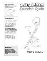
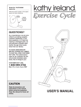
5. Hold the Handlebar Post (19) near the Frame (13)
as shown. Feed the Resistance Cable (6) and the
Reed Switch Wire (4) into the Frame, and then slide
the Handlebar Post into the Frame. Be careful not
to pinch the Resistance Cable or the Reed
Switch Wire. Attach the Handlebar Post with three
M10 x 22mm Button Head Bolts (55) and three M10
Lock Washers (61).
The Console (5) requires two 1.5V batteries (not
included). Alkaline batteries are recommended.
Refer to the inset drawing. Locate the battery door
on the back of the Console. Slide the battery door to
the left and open it as shown. Press two batteries
into the battery clip, with the negative (–) ends of the
batteries touching the springs. Close the battery
door and slide it to the right.
61
61
55
55
55
5
13
4
6
19
5
Batteries
Battery Clip
Battery
Door
CONDITIONING GUIDELINES
The following guidelines will help you to plan your
exercise program. Remember that proper nutrition
and adequate rest are essential for successful results.
EXERCISE INTENSITY
Whether your goal is to burn fat or to strengthen your
cardiovascular system, the key to achieving the
desired results is to exercise with the proper intensity.
The proper intensity level can be found by using your
heart rate as a guide. The chart below shows recom-
mended heart rates for fat burning, maximum fat burn-
ing, and cardiovascular (aerobic) exercise.
To find the proper heart rate for you, first find your age
at the top of the chart (ages are rounded off to the
nearest ten years). Next, find the three numbers
below your age. The three numbers are your “training
zone.” The lowest number is the recommended heart
rate for fat burning; the middle number is the heart
rate for maximum fat burning; and the highest
number is the heart rate for aerobic exercise.
Burning Fat
To burn fat effectively, you must exercise at a rela-
tively low intensity level for a sustained period of time.
During the first few minutes of exercise, your body
uses easily accessible carbohydrate calories for ener-
gy. Only after the first few minutes of exercise does
your body begin to use stored fat calories for energy.
If your goal is to burn fat, adjust the intensity of your
exercise until your heart rate is near the lowest num-
ber in your training zone as you exercise.
For maximum fat burning, adjust the intensity of your
exercise until your heart rate is near the middle num-
ber in your training zone as you exercise.
Aerobic Exercise
If your goal is to strengthen your cardiovascular sys-
tem, your exercise must be “aerobic.” Aerobic exer-
cise is activity that requires large amounts of oxygen
for prolonged periods of time. This increases the
demand on the heart to pump blood to the muscles,
and on the lungs to oxygenate the blood. For aerobic
exercise, adjust the intensity of your exercise until
your heart rate is near the highest number in your
training zone.
WORKOUT GUIDELINES
Each workout should include three important parts: a
warm-up, training zone exercise, and a cool-down.
Warming up—Begin each workout with 5 to 10 min-
utes of stretching and light exercise. A proper warm-
up increases your body temperature, heart rate and
circulation in preparation for exercise.
Training zone exercise—After warming up, increase
the intensity of your exercise until your heart rate is in
your training zone for 20 to 30 minutes. (During the
first few weeks of your exercise program, do not keep
your heart rate in your training zone for longer than 20
minutes.)
Cooling down—Finish each workout with 5 to 10
minutes of stretching. This will increase your flexibility
and will help to prevent post-exercise problems.
EXERCISE FREQUENCY
To maintain or improve your condition, plan three work-
outs each week, with at least one day of rest between
workouts. After a few months of regular exercise, you
may complete up to five workouts each week if
desired. Remember, the key to success is make exer-
cise a regular and enjoyable part of your everyday life.
Caution: Be sure to progress at your own pace
and avoid overdoing it. Incorrect or excessive train-
ing may result in injury to your health.
WARNING: Before beginning any exercise
program, consult your physician. This is espe-
cially important for persons over the age of 35
or persons with pre-existing health problems.
5
20
22
4
4. Identify the Left Pedal (20); there is an “L” on the
Left Pedal for identification. Using an adjustable
wrench, tighten the Left Pedal counterclockwise into
the left arm of the Crank (22).
Tighten the Right Pedal (not shown) clockwise into
the right arm of the Crank (22).
b.p.m.
AGE
AEROBIC
MAX. FAT
FAT BURN
19
61
55
18
6. Attach the Handlebar (18) to the Handlebar Post
(19) with two M10 x 22mm Button Head Bolts (55)
and two M10 Lock Washers (61).
6
710
8. Make sure that all parts are tightened before you use the exercise cycle. To protect the floor from damage,
place a mat beneath the exercise cycle.
The pulse
mode—To use
the pulse
mode, the
pulse monitor
must be worn.
Plug the pulse
monitor into
the jack on the
left side of the
console and
attach the pulse monitor to your left ear lobe.
Slide the metal clothes clip onto your collar.
Next, repeated-
ly press the
mode button
until a “P”
appears in the
display. (Make
sure that there
is not an arrow
under the scan
symbol.) When
your pulse is
detected, the
heart-shaped indicator will flash each time your
heart beats. After a few seconds, three dashes
will appear and your pulse will be shown. For the
most accurate pulse measurement, wait for
about ten seconds.
If your pulse is not shown, rub your ear lobe and
reposition the pulse monitor. It may be helpful to
stop pedaling whilst you measure your pulse.
The scan
mode
Repeatedly
press the
mode button
until an arrow
appears under
the scan symbol. When the scan mode is selected,
the console will display the pulse, speed, time,
distance, lap and calorie modes, for 5 seconds
each, in a repeating cycle.
The speed,
time, distance,
lap, or calorie
mode
Repeatedly
press the mode
button until an
arrow appears below or above the desired mode
symbol. Make sure that there is not an arrow
under the scan symbol.
If desired, press the on/reset button to reset the
display.
Turn off the power
To turn off the power, simply wait for about
six minutes. If the pedals are not turned and the
buttons are not pressed for six minutes, the
power will turn off automatically.
HOW TO SELECT KILOMETRES OR MILES
The console can display distance and speed in either
kilometres or miles. If a “KPH” appears in the display,
distance and speed will be shown in kilometres; if a
“KPH” does not appear, distance and speed will be
shown in miles.
To change the unit of
measurement, first
remove the four
screws attaching the
console (see draw-
ing 1). Lift the con-
sole a few inches
and turn it over,
being careful not to
pull on the wires.
Next, look into the
hole below the bat-
tery door, and locate
the small switch (see
drawing 2). (Note: It
may be necessary to
look into the hole
and to the left side to
find the small
switch.) Slide the
switch up or down to change the unit of measurement.
Reattach the console with the four screws.
5
Mode Button
Mode
Arrow
Pulse
Monitor
Clothes
Clip
Mode
Arrow
1
Screws
2
5
50
7. Plug the Pulse Monitor (50) into the jack on the left
side of the Console (5). Make sure that the wire
clothes clip is on the Pulse Monitor.
7
Wire
Clothes
Clip
Switch
Battery
Door
HOW TO ADJUST THE SEAT
For effective exer-
cise, the Seat (8)
should be at the
proper height; as
you pedal, there
should be a slight
bend in your knees
when the pedals
are at the lowest
position. To adjust
the Seat, first turn
the Seat Knob (3)
counterclockwise
several turns to loosen it. Next, pull back the Seat
Knob, slide the Seat Post (9) to the desired height,
and release the Seat Knob. Move the Seat Post up
or down slightly until it locks into place. Turn the
Seat Knob clockwise to tighten it.
HOW TO ADJUST THE PEDALING RESISTANCE
To vary the intensi-
ty of your exercise,
the pedaling resis-
tance can be
adjusted. The
resistance is con-
trolled with the
Resistance Knob
(10). As you turn
the Knob, the win-
dow at the bottom
of the console will show which resistance level you
have selected. Level 0 is the easiest level, and level
10 is the most challenging.
HOW TO ADJUST THE PEDAL STRAPS
To adjust each
Pedal Strap (64),
pull the end of the
Pedal Strap off the
tab on the pedal.
Align the desired
hole in the Pedal
Strap with the tab
and press the
Pedal Strap back onto the tab.
DESCRIPTION OF THE CONSOLE
The innovative
console offers a
manual mode
and three pacer
programs. The
pacer programs
are designed to
help you achieve
specific exercise
goals by pacing
your exercise.
You can choose
from a stamina-
building Interval
program, an
Aerobic program,
and a special Fat
Burn program. As
you exercise, seven monitor modes will provide con-
tinuous exercise feedback. The monitor modes are
described below:
Pulse—This mode shows your heart rate when
the pulse monitor is used.
Speed—This mode shows your pedaling pace, in
kilometres or miles per hour (see HOW TO
SELECT KILOMETRES OR MILES on page 10).
Time—If you select the manual mode, this mode
will show the elapsed time. If you select one of
the three pacer programs, this mode will count
down the time remaining in the program.
Distance—This mode shows the distance you have
pedaled, in kilometres or miles.
Lap—This mode shows the number of laps you
have completed. One lap equals 0.25 kilometres
or miles.
Calorie—This mode shows the approximate
number of calories you have burned.
Scan—This mode displays the other six modes,
for 5 seconds each, in a repeating cycle.
98
HOW TO USE THE PROFORM
®
870E
8
9
3
10
HOW THE PACER PROGRAMS OPERATE
When you use a
pacer program, two
columns of bars
will appear in the
display. The left
column represents
a target pace, and
the right column
shows your actual
pedaling pace. The target pace will change periodical-
ly during the program; as the target pace changes,
simply adjust your pedaling pace to keep both
columns at the same height. Important: The target
pace is a goal pace. Your actual pace may be slow-
er than the target pace, especially during the first
few months of your exercise program. Be sure to
exercise at a pace that is comfortable for you.
The three graphs
on the console
show how the tar-
get pace will
change during the
programs. Each
graph is divided
into ten columns of bars. Each column represents a
two-minute period, and each bar represents a target
pace of 5 mph (8 kph). In graph P1, for example, there
is one bar in the farthest left column. This shows that
during the first two minutes of program P1, the target
pace will be 5 mph (8 kph). In the second column
there are five bars. This shows that during the second
two-minute period, the target pace will be 25 mph (40
kph). Each program will last for twenty minutes.
STEP-BY-STEP CONSOLE OPERATION
Before the console can be operated, batteries
must be installed. (See assembly step 5 on page 6.)
Follow the steps below to operate the console.
Turn on the power
To turn on the
power, press
the on/reset
button or
simply begin
pedaling. The
entire display
will appear for two seconds; the console will then
be ready for use. Note: If batteries were just
installed, the power will already be on.
Select one of the three pacer programs or the
manual mode
To select one of
the pacer
programs,
repeatedly press
the program
button. The pro-
gram indicator
will show which
program you
have selected.
To select the
manual mode, press the program button until the
program indicator disappears. The programs will
be selected in the following order: program 1
(Interval), program 2 (Aerobic), program 3 (Fat
Burn), manual mode.
Begin your workout
If you selected
the manual
mode, go to
step 4. If you
selected one of
the pacer pro-
grams, two
columns of bars
will appear in
the display. The left column will show one bar,
showing that the target pace is 5 mph (8 kph).
The right column will show your actual pedaling
pace. Adjust your pedaling pace until only one
bar appears in the right column. Each time the
target pace changes during the program, adjust
your pedaling pace to keep both columns at the
same height.
Follow your progress with the LED track and
the seven monitor modes
The LED
track—The
LED track rep-
resents a dis-
tance of 0.25
kilometres or
miles. As you
pedal, the indi-
cators around
the track will light one at a time until you have com-
pleted one lap. A new lap will then begin.
4
3
2
1
Actual Pace
Program Indicator
Program Button
Target Pace
On/Reset Button
Actual Pace
Target Pace
Tab
64
  • Page 1 1
  • Page 2 2
  • Page 3 3
  • Page 4 4
  • Page 5 5
  • Page 6 6
  • Page 7 7
  • Page 8 8

ProForm 870e Owner's manual

Category
Fitness, gymnastics & weight training
Type
Owner's manual
This manual is also suitable for

ProForm 870e is a versatile exercise cycle designed to provide a full-body workout in the comfort of your home. With its user-friendly console, you can track your progress and stay motivated during your workouts. The adjustable resistance levels allow you to customize your workout intensity, making it suitable for users of all fitness levels. Whether you're a beginner looking to improve your cardiovascular health or an experienced cyclist seeking an intense workout, the ProForm 870e has something to offer.

Ask a question and I''ll find the answer in the document

Finding information in a document is now easier with AI