Craftsman 113.228000 Owner's manual
- Category
- Lathes
- Type
- Owner's manual
This manual is also suitable for

ISears
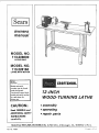
MODEL NO.
113.228000
LATHE ONLY
MODEL NO.
113.228160
LATHE WiTH MOTOR
Serial
Number.
Modet and serial
number may be found
under belt guard.
You should record both
model and serial number
in a safe place for
future use.
CAUTIION:
Read GENERAL and
ADDITIONAL SAFETY
iNSTRUCTIONS
carefully
CRI!IFTSMttN_
12-INCH
WOOD-TURNING LA THE
®assembly
e operating
• repair parts
Sold by SEARS, ROEBUCK AND CO., Chicago, IL. 60684 U.S.A.
Part No. 70053 Prir_,_ed tr_ Li_.A

FULL ONE YEAR WARRANTY ON CRAFTSMAN WOOD LATHE
If Within one year from the date of purchase, this Craftsman Wood Lathe fails due to a defect in material or
workmanship, Sears will repair it. free of charge.
WARRANTY SERVICE IS AVAILABLE BY SIMPLY CONTACTING THE NEAREST SEARS STORE OR
SERVICE CENTER THROUGHOUT THE UNITED STATES.
This warranty gives you specific legal rights, and you may also have other rights which vary from state to state.
SEARS, ROEBUCK AND CO., Dept. 698/731A, Sears Tower, Chicago, IL 60684
general safety instructions for
1. KNOW YOUR LATHE 13.
Read and understand owner's manual and labels affixed to
the tool. Learn its application and limitations as well as its
specific potential hazards peculiar to this toot. 14.
2. GROUND THE LATHE
This Lathe is equipped with an approved 3-conductor 15.
cord and a 3:prong grounding type plug to fit the proper
grounding type receptacle. The green conductor in the
cord is the grounding wire. Never connect the green wire
to a live terminal.
3. KEEP GUARDS IN PLACE
- n working order, and n proper adjustment and align-
ment.
4. REMOVE ADJUSTING KEYS AND WRENCHES
Form habit of checking to see that keys and adjusting 17.
wrenches are removed from toot before turning it on.
5. KEEP WORK AREA CLEAN
Cluttered areas an_ benches invite accidents. Floor must
not be sl ippery due to wax or sawdust. 18.
6. AVOID DANGEROUS ENVIRONMENT
Don't use power tools in damp or wet locations or expose
them to rain. Keep work area well lighted. Provide ade-
quate surrounding work space.
7. KEEP CHILDREN AWAY
Alt visitors should be kept a safe distance from work area.
8. MAKE WORKSHOP KID-PROOF
-- with padlocks, master switches, or by removing starter
keys,
9. USE PROPER SPEED
The Lathe will do the job better and safer when operated
at the proper speed.
10. USE RIGHT TOOL
Don't force tool or attachment to do a job for which it
was not designed.
11, WEAR PROPER APPAREL
Do not wear loose clothing, gloves, neckties or jewelry
_rings; wristwatches) to get caught in moving parts. 21.
NONSLIP footwear is recommended. Wear protective
hair covering to contain long hair. Roll long sleeves
above the elbow.
12. USE SAFETY GOGGLES (Head Protection) 22.
Wear safety goggles (must comply wilh ANSI Z87.1) at alt
times. Everyday eyeglasses only have impact resistant len-
ses, they are NOT safety glasses. Also, use face or dust
mask if; cutting operation is dusty, and ear protectors
(plugs or muffs) during extended periods of operat on.
power tools
SECURE WORKPIECE
Mount workpiece securely between centers.
DON'T OVERREACH
Keep proper footing and balance at at_times.
MAINTAIN TOOLS WITH CARE
Keep tools sharp and clean for best and safest perform-
ance. Follow instructions for lubricating and changing
accessories.
16. DISCONNECT YOUR LATHE
before servicing; when changing accessories or attach-
ments.
AVOID ACCIDENTAL STARTING
Make sure switch is in "OFF" position before plugging
in
USE RECOMMENDED ACCESSORIES
Consult this owner's manual for recommended accessories.
FoIIow the instructions that accompany the accessories.
The use of improper accessories may cause hazards.
19. NEVER STAND ON LATHE
Serious injury could occur if the Lathe tips over.
Do not store materials such that it is necessary to stand
on the toot to reach them.
20. CHECK DAMAGED PARTS
Before further use of the Lathe, a guard or other part that
is damaged should be carefully checked to ensure that it
will operate properly and perform its intended function.
Check for alignment of moving parts, binding,of moving
parts, breakage of parts, mounting, and any other con-
ditions that may affect its operation, A guard or other
part that is damaged should be properly repaired or
replaced.
DIRECTION OF FEED
Apply cutting tool to the workp[ece against the direction
of spindle ro_ation
NEVER LEAVE LATHE RUNNING
ATTENDED
Turn power "OFF". Don't leave Lathe until it comes to a
complet_ stop.

additionam safety instructions for wood turning lathes
Safety is a combination of operator common sense and
alertness at all times when the Lathe is being used,
WARNING: FOR YOUR OWN SAFETY, DO 7.
NOT ATTEMPT TO OPERATE YOUR LATHE
UNTIL IT IS COMPLETELY ASSEMBLED AND
INSTALLED ACCORDING TO THE INSTRUC-
TIONS... AND UNTIL YOU HAVE READ 8.
AND UNDERSTAND THE FOLLOWING:
PAGE
1. General Safety Instructions .................. 2
2. Getting to Know Your Lathe .............. 13
3. Basic Lathe Operation ................... t5
4. Maintenance ......................... 19
5. The Lathe and motor must be bolted down to a stand
or workbench for stability.
6. Protection: Eyes, Hands, Face, Ears, Body
a. Wear safety goggles that comply with ANSI Z87.1-
1968, and a face shield if operation is dusty. Wear
ear plugs or muffs during extended periods of
operation.
b. When turning between centers or on the faceplate,
always rough-out "out of round" workpieces at
slow speed. Running l_e Lathe too fast, so that it
vibrates, could cause the workpiece to be thrown
from the Lathe . .. or the turning tool to be jerked
from your hands.
c. Always revolve the workpiece by hand before turn-
ing on the motor. If the workpiece strikes the toot
rest, it could split and be thrown out of the Lathe,
Do not allow the turning tool to '*bite" into the
workpiece which could result in splitting of the
workpiece or the workpiece being thrown from the
Lathe. Always position the tool rest above the
centedine of the Lathe for spindle turning. Do not
apply the turning tool to the workpiece below the
level of the tool rest.
Do not run the Lathe in the wrong direction. This
could cause the turning tool to be thrown from
your hands. The Lathe must run in a direction so
that the workpiece turns toward you.
Before attaching a workpiece to the faceptate aft
ways "rough it out" to as "true round" as possible.
This will minimize vibration while turning,
Always fasten the workpiece securely to the face-
plate.
Failure to perform these set-up operations could
cause the workpiece to be thrown from the Lathe,
Avoid awkward hand positions, where a sudden
slip could cause a hand to move into the workpiece.
h. Remove all loose knots before installing workpiece
between centers or on the faceplate.
i. Never leave the Lathe work area with the power on
before the Lathe has come to a complete stop, or
without removing and storing the switch key.
j. Never operate the Lathe with protective cover on
the unused shaft end of the motor removed,
Hang your turning tools on the wall toward the tail-
stock end of the Lathe. Do not lay them on the bench
so that you must reach over the revolving workpiece
to select them,
9.
Keep firm hold and control of the turning tool at all
times. Special caution must be exercised when knots or
voids are exposed to the turning tool.
Note the following DANGER label which appears on
the front of the belt guard.
DANGER
FOR YOUR OWN SAFETY:
READ AND UNDERSTAND THE OWNER'S
MANUAL BEFORE OPERATING MACHINE:
1. WEAR SAFETY GOGGLES PER ANSI Z87,1
AND FACE SHIELD IF OPERATION IS
DUSTY=
2. DO NOT WEAR GLOVES, NECKTIES, OR
LOOSE CLOTHING_ TIE BACK LONG HAIR.
3. BE POSITIVE ALL LOCKS ARE TIGHT BE-
FORE OPERATING MACHINE,
4. TURN WORKPIECE BY HAND BEFORE
APPLYING POWER TO DETERMINE IF IT
CLEARS THE TOOL REST OR OTHER MA-
CHINE PARTS.
5, ROUGH OUT FACEPLATE WORKPtECES
BEFORE INSTALLING ON FACEPLATE TO
AVOID EXCESSIVE VIBRATION AND POS-
SIBLE INJURY,
6, DO NOT MOUNT SPLIT OR CHECKED
WORKPIECE OR ONE CONTAINING KNOT.
7. ALWAYS USE LOWEST SPEED WHEN
STARTING A NEW WORKPIECE, USING
FACEPLATE OR TURNING BETWEEN CEN-
TERS, TO MINIMIZE POTENTIAL INJURY,
10. Think Safety.
tl, Complete hand sanding of between-centers or
faceplate mounted workpieees BEFORE removing
from the lathe. Do not exceed the speed used for the
last cutting operation performed on the workpiece, in
accordance with the speed chart.
12. NEVER attempt to remount a faceplate turning to
the faceplate for any reason. NEVER attempt to
remount a between-centers turning if the origina]
centers in the turning have been altered or removed.
BE POS|TIVE the lathe is set at the lowest speed if
remounting a between-centers turning with
non-altered original centers.
13. Use extra caution in mounting a between-centers or
spindle turning to the faceplate, or a faceplate turning
to _)etween-centers, for subsequent operations. BE
POSITtVE the lathe is set at the lowest speed before
turning ON.
14. NEVER mount a workpiece that contains any splits,
checks, or loose knots to a faceplate or between
centers.
15. Do not perform any operation when hand holding the
workpiece. Do not mount a reamer, milling cutter,
wire wheel, buffing wheet, or a drill bit to the
headstock spindle.
16. Use the drill chuck accessory in the tai_ stock only.
Do not mount ar_y drill that extends more than 6
inches beyond chuck jaws,

additional safety instructions for wood turning lathes
WARNING:
(GAINED FROM FREQUENT USE OF YOUR
MACHINE) TO BECOME COMMONPLACE.
ALWAYS REMEMBER THAT A CARELESS
FRACTION OF A SECOND IS SUFFICIENT TO
INFLICT SEVERE INJURY,
DO NOT ALLOW FAMILIARITY WARNING_ THE FOUR STEP LATHE AND
MOTOR PULLEYS FURNISHED ARE DE-
SIGNED TO RUN THE LATHE AT THE COR-
RECT SPEEDS WHEN USED WITH A 1725
R.P.M. MOTOR. DO NOT USE A 3450 R.P.M.
MOTOR TO INCREASE THE SPEED BECAUSE
IT COULD BE DANGEROUS.
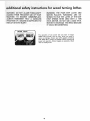
WEAR YOUR
The operation of anv power tool can result in foreign
objects being thrown into the eyes, which can result in
severe eye damage. Always wear safety goggles complying
with ANSI Z87.1 (shown on Package) before commencing
power tool operation. Safety Goggles are available at Sears
retail or catalog stores.
4

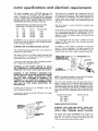
This Lathe is designed to use a 1725 RPM motor only. Do
not use any motor that runs faster than 1725 RPM. It is
wired for operation on 110-120 volts, 60 Hz., alternating
current. IT MUST NOT BE CONVERTED TO OPERATE
ON 230 VOLTS. EVEN THOUGH SOME OF THE RE-
COMMENDED MOTORS ARE DUAL VOLTAGE.
THESE MOTORS HAVE BEEN FOUND TO BE
ACCEPTABLE FOR USE ON THIS TOOL.
HP RPM VOLTS CATALOG NO.
I/3 1725 110-t20 1282
1/2 t725 110-120 1278
}/2 1725 110-t20 1279
I/2 1725 110-120 t289
CAUTION: Do not use blower or washing machine motors
or any motor with an automatic reset overload protector
as their use may be hazardous.
CONNECTING TO POWER SOURCE OUTLET
This machine must be grounded while in use to protect the
operator from electric shock.
Plug power cord into a 1 I0-120V properly grounded type
outlet protected by a 15-amp. dual element time delay or
Circuit-Saver fuse or circuit breaker.
If you are not sure that your outlet is properly grounded,
have it checked by a qualified electrician.
WARNING: DO NOT PERMIT FINGERS TO TOUCH
THE TERMINALS OF PLUGS WHEN INSTALLING OR
REMOVING THE PLUG TO OR FROM THE OUTLET.
WARNING: IF NOT PROPERLY GROUNDED THIS
POWER TOOL CAN INCUR THE POTENTIAL HAZARD
OF ELECTRICAL SHOCK. PARTICULARLY WHEN
USED IN DAMP LOCATIONS IN PROXIMITY TO
PLUMBING. IF AN ELECTRICAL SHOCK OCCURS
THERE IS THE POTENTIAL OF A SECONDARY HAZ-
ARD SUCH AS YOUR HANDS CONTACTING THE
CUTTING TOOL.
If power cord is worn or cut, or damaged in any way,
have it replaced immediately.
If your unit is for use on less than 150 volts it has a plug
that looks like below.
PROPERLY
GROUNDED
OUTLET,_
J
[n ul
@
fff U)
3--PRONG
PLUG
GROUNDING
PRONG
This power tool is equipped with a 3-conductor cord and
grounding type plug which has a grounding prong, approved
by Underwriters" Laboratories. The ground conductor has
a green jacket and is attached to the tool housing at one
end and to the ground prong in the attachment plug at the
other end.
This plug requires a mating 3-conductor grounded type
outlet asshown.
If the outlet you are planning to use for this power tool is
of the two prong type DO NOT REMOVE OR ALTER
THE GROUNDING PRONG IN ANY MANNER, Use an
adapter as shown and always connect the grounding lug
to known ground.
It is recommended that you have a qualified electrician
replace the TWO prong outlet with a properly grounded
THRE_E prong outlet.
An adapter as shown below is available for connecting
plugs to 2-prong receptacles. The green grounding lug
extending from the adapter must be connected to a per-
manent ground such as to a properly grounded outlet box,
MAKE SURE THIS IS GROUNDING LUG
CONNECTED TO __
KNOWN GROUND ADAPTER
RECEPTACLE
NOTE: The adapter illustrated is for use only if you already
have a properly grounded 2-prong receptacle.
The use of any extension cord wilt cause some loss of
power. To keep this to a minimum and to prevent over-
heating and motor burn-out, use the table below to deter-
mine the minimum wire size (A.W.G,) extension cord. Use
only 3 wire extension cords which have 3-prong grounding
type plugs and 3-pole receptacles which accept the tools
plug.
Ex_nsion Cord Len_h Wire Size A.W.G.
Up_100 Ft. 16
t00-2OOFt. 14
200-400 Ft. 10
CHECK MOTOR ROTATION
WARNING: FOUR YOUR OWN SAFETY, MAKE SURE
PLUG IS NOT CONNECTED TO POWER SOURCE
OUTLET WHEN CHANGING MOTOR ROTATION.
The motor must rotate CLOCKWISE when viewed from
the shaft end to which you will mount the pulley. {See
page 12,) If it does not, change the direction according
to the instructions furnished with the motor.

UNPACKING ANDCHECKING CONTENTS ....... 6 Tailstock ram lock ....................... 13
7 Tailstock 10ck . ......................... 13
ASSEMBLY ............. ...... _..........
+MoUnting Lathe and motor on recommended On : off switch .......................... 13
Craftsman bench .......................... 7
SpUr and cup center instaliati0n . . • .... ....... 9
Off'and on +;witch .... ; . ......... . . , . .., . . 10
Check motor rotation , ...................... 12
GETTING TO KNOW YOUR WOOD LATHE ....... 13
Belt guard lock .......................... 13
Index pin ............................. 13
Spindle lock hole ........................ t3
Tool rest lock .......................... 13
Tool rest base lock ....................... 13
Handwheel ............................ 13
Spur center and cup center (aligning centers) ...... 14
Tailst0ck .............................. 14
Speed chart ............................ 15
BASIC LATHE OPERATION .................. 15
Changing speeds ......................... 15
Spindle turning ......................... 16
Indexing .............................. 18
MAINTENANCE .......................... 19
LUBRICATION ........................... 19
RECOMMENDED ACCESSORIES .............. 21
REPAIR PARTS .......................... 22
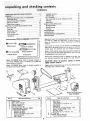
TOOLS NEEDED
318-inch wrench +;,.i
Screwdriver {medium) I="
7/16-inch wrench Framin s are +__
I_.?,T,yrtT.++ _L?.'t ? :._',.",+_.:tA'.t t " t .+;,+:;.,.L-L.J.
Model 113.228000 Wood Lathe is shipped complete in
one carton (without motor, or bench). The V-Belt and
motor pulley are furnished,
Model ! 13.228160 Wood Lathe is shipped complete in
one carton and includes a Motor.
A
G
\
F
Separate all parts from packing materials and check each
one with the "Table of Loose Parts" to make certain all
items are accounted for, before discarding any packing
material.
If any parts are missing, do not attempt to assemble the
lathe olug in the power cord or turn the switch on until the
missing parts are obtained and are installed correctly.
Using a 7/16" wrench, remove the wood blocks attached to
the Lathe. Save the nuts, bolts and washers, you wilt need
for attaching the Lathe to the bench.
Remove the protective oil that is applied to the bed. Use
any ordinary household type grease and spot remover.
CAUTION: Never use gasoline, naptha or similar
highly volatile solvents.
Apply a coat of automobile wax to the bed, Wipe all parts
thoroughly with a ciean dry cloth,
MOTOR INCLUDED WiTH
Model 113.228160
item
BA
C
D
E
F
Table of Loose Parts Qty.
Motor Pulley : '. .... i, .' ...... '. +' .... 1
Belt, "Vee t/2 × 37 .... + ........... 1
Wood Turning Lathe ................ 1
Owner's Manua4 ................... 1
Belt Guard Assembly ................ 1
Loose Parts Bag -- Part No. 70046
Containing the following:
1
Wrench, Hex 5/32.
Wrench, Hex3/16,1_iiil; _i_ i ii _; 1
Screw, Type 23Pan 10-32 x 3/8 ...... 4
Nut+ Hex 3/4-t6 ................. t
Spur, Center ................... 1
item
Table of Loose Parts Qty.
Cup, Center .................... 1
Point, Center ................... 2
Lockwasher Ext. Tooth No. 10 ....... 4
Key, Switch .................... 1
Clamp Cord .................... 2
Bolt Rd. Hd. Carriage 1/4-20 x 1-3/4 . . , 4
Washer t7/64 x 47/64 x t/16 ........ 4
Nut Hex 1/4-20 ................. 4
ScrewPan Hd. Ty. ANo. 8x 1/2 ...... 4
6" Tool Rest ..................... 1
Booklet, How To Operate
Your Craftsman Lathe ............. 1

assembly
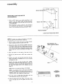
MOUNTING LATHE AND MOTOR
ON WORKBENCH
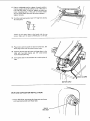
Dril{ six 3/8" holes in your bench according to the
diagram to the right. NOTE; Make sure the top of your
bench is positioned so that you don't drill into the legs
or rail underneath.
When mounting to a Sears workbench, side overhang of
top at headstock end should be 5" from leg portion of
stand. (Front overhang of top shoutd remain 1-1/8"').
_-- 6 1/8" _3'_
HOLES FOR MOTOR
14 5/8"
HOLESFO. AT.E\ = f ..
J \ 1,3l,°
F,O.,OFBENc,i T
LOCATION OF MOUNTING HOLES
NOTE: To attach your Lathe to the bench, use the bolts,
nuts and washer you removed when unpacking.
2. Position Lathe on bench and insert two bolts through
holes in headstock butdo not screw on the nuts.
3. Position the Lathe so that the bed is parallel to the front
of the bench. Check the foot, If the bottom of the foot
is not flat on the surface of the bench, loosen the screw
in the foot, tap the screw to loosen the tocknut inside.
Turn the foot so it is flat on the bench and tighten the
screw.
4. Mark the location on the bench of the hole in foot.
5. Remove the Lathe and drill a 3/8" hole to attach the
foot.
6. Position the Lathe and insert the bolts from the top.
Place a flat washer, a Iockwasher and a nut on the bolts
and tighten the nuts.
7. Position the motor over the mounting holes. NOTE:
When using a Craftsman double shaft motor, make sure
the 5/8" dia. shaft is to the left when facing the front of
the Lathe. For motors with a 1/2" diameter shaft see
Step 15.
NOTE: Motor is inciuded with Model 113.228160.
NOTE: The ventilation holes in the motor should NOT
face upward as sawdust can collect inside the motor. If
necessary, loosen the two motor base clamp screws and
rotate the motor. Then, tighten the clamp screws,
8. Find four 1-3/4" carriage bolts, flat washers and nuts
from among the toose parts (see illustration).
9. Insert the botts from the top. Place a flat washer and a
nut on the bolts but do not tighten the nuts at this
time.
!-3/4"
BED PARALLEL TO
FRONT EDGE OF BENCH
FOOT

assembly
/
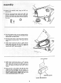
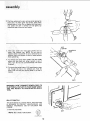
10. Remove the headstock pulley-using the 5/32" set-
screwwrench.
11: Find four pan head thread cutting screws 3/8" long
and four Iockwashers from among the loose parts.
Attach the belt guard with these screwsand Iockwash-
er_ The arrows in this illustration showthe location of
the screws.
°i
/
/
12, Place the t_eadstock pulley onto the headstock shaft as
shown. Position it so that the end of the put|ey is flush
with the end of the lathe spindle.
13. Place the motor pulley on the motor shaft so that the
small diameter is approximately 1/16" away from the
motor.
14. NmOoToEr:shWhf_n_1_s_l _tgrteh_hPa_It_/eO_/;65fS"_lud_ra_n_tee;
furnished with your motor is in place. Then tighten the
setscrew with a 5/32" setscrew wrench.
/
/
/
/
/
3/16 x 3/16 KEY
15. NOTE: When installing the pulley on a 112" diameter
motor shaft, make sure that the adapter sleeve and
3/I6" square key furnished with your motor are in
place. Then tighten the setscrew with a 5/32" setscrew
wrench,
16, Place the belt on the pulleys and slide the motor
toward the rear of workbench until al_lthe slack is re*
moved from the belt. NOTE: 1/2 inch deflection of
belt under moderate pressure,applied between the two
pulleys is adequate :tenSion, Tighten only two of the
motor mounting boltsusing a7/16 wrench.
ADAPTER SLEEVE
T
1/2 DIA. MOTOR SHAF

17. Place a straightedge such as a piece of wood, metal or
framing square across the pulleys to see if they are in
line with each other, If they are, tighten the other two
motor mounting bolts. If they are not in line, loosen
the two motor bolts and move the motor sideways...
tighten the bo_ts,
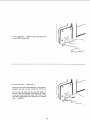
18, Find four pan head wood screws 1/2" long from among
the loose parts.
Attach the belt guard plate to the bench with the two
screws. Make sure the plate is PARALLEL to the belt.
19. Plug motor cord into outlet on back of switch box. DO
NOT plug motor cord into power source outlet,
20+ Position the two cords as shown and clamp them to the
table with two cable clamps and 1/2" wood screws
from the loose parts bag.
21. Coil up the slack in the cord and tie it with apiece of
tape.
CLAMPS
MOTOR CORD
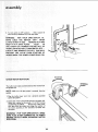
SPUR AND CUP/CENTER INSTALLATION
!. Find a 3/4-16 hex nut among the loose parts and screw
onto head stock spindle until finger tight.
3/4-16
HEX NUT
/
9

:::_i:::i/:i:_!i ::_ /:i!_:i; ;_ii ¸ i/ /_ • : : ............
2. Find two pointS and a spur and cup center among the
1o0se parts. To insert point into centers, place center
between jaws of a Vise.Do not tighten vice. Insert point
into center and with a hammer and nail gently tap
around the baseof the point until secure,
3. Insert Spur center into head stock spindle and cup
Center into tailstock ram. NOTE: Do no_ drive or
hammer centers into spindle or ram as removal may be
difficult- Use:a soft hammer or block of wood and give
them agentle tap,
4. To remove spur center from spindle, hold the spindle
pulley with one hand and, Using a wrench or pair of
pliers, turn the hex nut counterclockWise until center
isejected.
5, To remove cup Center insert a 114""wood dowel or brass
rod through the hole in the tailstock ram. Hold the
center with one hand and tap the-dowel or rod with a
hammer,
\
TAILSTOCK
RAM
/
FOOT
WARNING: DON'TCONNECT POWER CORD TO
ELECTRICAL OUTLET IN YOUR SHOP UNTIL
YOU ARE READY TO CHECK MOTOR ROTA-
TION.
ON-OFF SWITCH
The On-Off Switch has a locking feature. THIS FEATURE
IS INTENDED TO PREVENT UNAUTHORIZED AND
POSSIBLE HAZARDOUS USE BY CHILDREN AND
OTHERS,
1. Insert key into switch.
NOTE: Key ismade of vetlowplastic.
©
K_Y
(YELLOW _l._ S'{ IC]
KEY
10

2. To turn Lathe ON, .. INSERT finger under switch lever
and pull END of switch out.
3. To turn Lathe OFF. ,, PUSH lever in.
Never leave the Lathe unattended until it has come to a
complete stop and you have removed the switch key.
Do not cycle the motor switch on and off rapidly, as
this may cause the faceplate or sanding disc to loosen.
In the event this should ever occur, stand clear of the
face plate or sanding disc until it has come to a complete
stop.., retighten it.
11

assembly
4. To lock switch in OFF position . . , HOLD switch IN
with one hand, REMOVE kev with other hand.
WARNING: FOR YOUR OWN SAFETY, AL-
WAYS LOCK THE SWITCH "OFF". WHEN
LATHE IS NOT IN USE ,.. REMOVE KEY AND
KEEP IT IN A SAFE PLACE . .. ALSO ,.. IN
THE EVENT OF A POWER FAILURE (ALL OF
YOUR LIGHTS GO OUT) TURN SWITCH OFF...
LOCK IT AND REMOVE THE KEY. THIS WILL
PREVENT THE LATHE FROM STARTING UP
AGAIN WHEN THE POWER COMES BACK ON.
HOLD co._o, /
\
CHECK MOTOR ROTATION
ROTATION
The Lathe must rotate counterclockwise when viewed from
the spindle end.
NOTE: Make sure the spur center is removed from the
spindle.
1. Plug the Lathe power cord into a properly grounded
outlet (See page 4)_
2. Standclearof the LathespindleandturntheswitchON.
Notice the rotation of the soindle.If it is NOT turning
COUNTERCLOCKWISE . . . Removethe Lathe power
cord plug from the outlet and changethe rotation of
the motor accordingto the directions furnished with
themotor.
WARNING: FOR YOUR OWN SAFETY, MAKE
SURE PLUG IS NOT CONNECTED TO POWER
SOURCE OUTLET WHEN CHANGING MOTOR
ROTATION.
TERMINAL
COVER
12 ¸

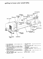
getting to know your wood Jathe
13
SPEED
INDEX PIN
BELT GUARD
1 BELT GUARD
LOCK
7 HANDWHEEL
TAILSTOCK
11spur RA.
CENTER 10CUPCENTE.
3SPINDLE
LOCK 8 TAILSTOCK RAM
HOLE
TOOL REST
TOOL REST
BASE
BASE
)INDLE
\
BED
FOOT
TAILSTOCK
LOCK
12 TA,LSTOCK
TOOL REST
LOCK
4 TOOL REST
BRACKET LOCK
1. BELT GUARD LOCK... Locksthe hinged part of the
guard during operation.
2. INDEX PIN... Engages with the spindle pulley to
determine equal spacing for cuts for fluting or feeding,
or for dividing face plate work. DO NOT USE FOR
REMOVING FACEPLATES.
3. SPINDLE LOCK HOLE ... For remov[ng faceptatesor
sanding discs, insert a setscrew wrench, large nail or
bolt in the hole to hold the spindle while unscrewing
facepiate or sanding disc.
4. TOOL REST BRACKET LOCK... Clamps the tool
rest bracket to the bed.
5. TOOL REST LOCK... Clamp the too/rest to thetool
rest base.
6. TOOL REST BASE LOCK... Clamps the tool rest
base to the bed.
7. HANDWHEEL... Adjusts the tailstockram,
8. TAILSTOCK RAM LOCK... Clamps the ram in the
tai|stock.
9. TAILSTOCK LOCK... Clamps the tailstock to the
bed.
10. ON-OFF SWITCH... Seepage10.
13

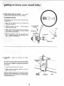
ow your wood lathe
11;SPUR: CENTER AND CUP CENTER .... are used for
spindle turning and should always be in alignment,
ALIGNING CENTERS
lithe centers:are not in line as shown, make the follow
ing adjustments.
1. Make sure the tailstock and ram are locked when
checking for alignment.
2. Loosen the screw in the foot... TAP the screw to
loosen the Iocknut inside,
3. Using a 3/16" setscrew wrench, loosen the setscrew
on the back of the headstock, The screw is located
about 1-3/4" from the bottom.
4. Swing the tailstock so that the two points are in
line. ,, tighten the setscrewir_ the headstock and the
screw in the end of the taitstock.
3/16" SETSCREW
WRENCH
\
HEADSTOCK r
3/16,,
SETSCREW
TAI LSTOC K
FOOT
SCREW
HANDWHEEL
12. TAILSTOCK., .supports the workpiece for spindle
turning.
The tailstock contains a brass screw which bears against
the "key" on the underside of the bed. This screw pre-
vents excessive"looseness" (rocking back and forth) of
the tailstock,
I. Loosen the Iocknut using a 7t 16" wrench.
2. Tighten the screw moderately against the key, then
loosen it about t/4 turn.
Slide the tailstock along the bed. If it does not stick or
bind in any one spot, tighten the nut. If it binds or sticks,
loosen the screw only enough so that the tailstock slides
smoothly a!ong, the bed.
TAI LSTOCK
LOCK
\
BRASS \
SCREW LOCKNUT KEY
14

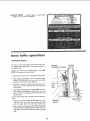
13. SPEED CHART,.. Indicates general
speedsfor varioussizesof workpieees.
recommended
SPINDLE SPEED
MOTOR SPINDLE
I L ,83?oI
22so t
II 'I"1 II 34so I
basic lathe operations
CHANGING SPEEDS
The belt is shown positioned on the second steps from
the outside end of the pulleys. This causes the lathe to
run 2250 R.P.M.
Suppose you wish to run the lathe slower - say, t350
R.P,M. You must shift the belt inward.
t. Make sure the power cord is removed from the outlet.
2. With the belt guard raised, rotate the motor pulley
COUNTERCLOCKWISE with your left hand while
pushing on the belt with your right hand.
3. Continue to rotate the pulley while pushing on the
belt until it "climbs" down into the third step of the
motor pulley.
4. Now rotatethe spindle pulley CLOCKWISE with your
right hand while pushing on the belt with your left
hand, The belt will cJimb up into the third step of the
spindle pulley.
To make the lathe go faster, the belt must be shifted o_t-
ward.
1. Rotate the spindle pulley CLOCKWISE with your
right hand, Pull on the belt while rotating the pulley
until it climbs down into the next smaller step.
2. Now rotate the motor pulley COUNTERCLOCKWISE
with yourlefthand while pulling on the belt with your
right hand. The belt will climb up into the next larger
step.
ROTATE MOTOR
COUNTERCLOCKWISE PULLEY
ON
BELT
SPINDLE
PULLEY
15

basic lathe operations
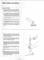
SPINDLE TURNING:
If you have never done anv amount ot wood turn ng,
:we suggest that you practice using the various wood
turning tools. Start with a small spindle turning.
Be sure to study the "Handbook" which you received
With Your lathe. It explain Sand illustrates the correct
use of the turning tools; the p0sitioning of:the to01
restand other information to helpyou gain experience.
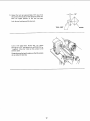
1 Select a oiece:ofWo0d 2"' x 2" x 12":
2. Draw diagonal _ines on each end to locate the centers.
3. On oneend, make a saw cut approximatel V 1/16" deep
on each diagonal line,; This is for tile spur center.
4. The other end is for the cup center. Place the point of
the cuPcenter On the wood where the d agonal lines
cross
DIAGONAL LINES
ON BOTH ENDS
5. Drive the cup center into the wood. Use a wooden
mallet or a plastic hammer. If you don't have one, use
asteel hammer, but put a piece of Wood on the end of
the cup center to protect it.
6. Remove the cup center and drive the spur center into
the other end of the wood. Make sure the spurs are in
the saw cuts. Remove the spur center.
7. Make sure the centers and the hole in the spindle and
the tailstock ram are clean. Insert the spur center into
the headstock and the cup center into the tailstock
and tap them in lightly with a piece of wood, Do not
drive them in.
8. Put a drop of oil or wax on the wood where it con-
tacts the cup center. This will lubricate the wood
while it isturning,
9. Place the wood between the centers and lock the tail-
" stock,
10. Move the cup center into _e wood by turning the
hand:wheel, _V_akesure that the cup center and spur
center are "seated" into the wood in 1heholes made
in steps 5 and 6 above, Rotate the wood by hand
while turning the hand wheel,
/

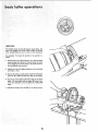
11. Adjust the too! rest approximately I/8" away from
thecorners ofthewood and 1/8" above the center line.
Note the angled position of the toot rest base.
Lock the tool rest base and the tool rest.
TOOL R EST
1/8"
WOOD
Look at the speed chart. Notice that a 2" square
turning up to 18" tong should run at 875 R.P.M. for
"roughing". Move the V-belt on the pulleys to the
slowest speed.
Rotate the wood by hand to make sure that the corners
do not strike the toot rest,
17

basic lathe operations
INDEXING
The spindle pulley contains 36 equally spaced holes. The
index pin engages with these holes to keep the spindle
from turning while you put a mark on the workpiece.
For example: To locate the position of six spokes in a
wheel:
1, Pull the index pin outward and turn it so that the small
cross pin slips into the slot. This will allow the index
pin toengagein one of the holes in the pulley and pre-
vent the spindle from turning.
2. AdjuSt the toot rest approximately at the centerline
and make a mark.
3, Pull out the index pin and slowly rotate the workpiece
until the pin slides into the next hole in the pulley.
4, Do this six times and put the next mark on the work-
piece, The _wo marks will be spaced 60° apart, Con-
tinue this operation until six spokes are marked 60 °
apart.
5. Spindle turnings can be divided in the samemanner.
18

maintenance
WARNING: FOR YOUR OWN SAFETY, TURN
SWITCH "OFF" AND REMOVE PLUG FROM
POWER SOURCE OUTLET BEFORE MAINTAIN-
ING OR LUBRICATING YOUR LATHE.
Frequently blow out any dust that may accumulate inside
the motor.
A coat of automobile-type wax applied to the bed will help
to keep the surfaces clean and allow the tool rest and tail-
stock to more more freely.
If the power cord is worn or cut, or damaged in any way,
have it replaced immediately.
For motor maintenance, follow instructions furnished with
motor.
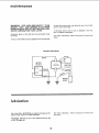
WIRING DIAGRAM
WHITE
MOTOR _ ........ r-- Insulated
OUTLET ! SWI I i_H ! Cap, Flag
I POWER
,=_ CORD
im =m
..... '11I'
lubrication
All of the BALL BEARINGS are packed with grease at the
factory. They require no further lubrication.
Periodically lubricate the ram in the tailstock with No. 20
or No. 30 engine oil.
For motor lubrication, follow instructions furnished with
the motor.
!9

TROUBLE SHOOTING CHART
TROUBLE PROBABLE CAUSE
ii.,
1. Defective On-Off switch,
Defective switch cord.
Defective switch box receptacle.
2. Motor protector open,
(only if your motor is
equipped with an
overload protector).
3, Burned out motor I
Motor will not run.
REMEDY
1. Replace defective parts before using Lathe
again,
2, Reset protector when motor has cooled.
3. Consult Sears Service. Any attempt to repair this
motor may create a HAZARD unless repair is
done by a qualified service technician. Repair
service isavailable at your nearest Sears Store.
.... t. Adjust bert tension, see Assembly Section.
: Lathe slows down 1. V-belt too loose
when turning
: Tailstock rocks • 1. Brass adjusting screw is too I Adjust screw. See Section, "Getting To Know
e"
back and forth loose. Your Lath .
excessively. ,
I I ee
Headstock oose _ 1. Setscrew not tight; :1. Tighten setscrew. S Section, "Getting To
on bed ....... _ . ; .... :KrioW Your Lathe". ..
Wood burnsat I i. CuP center too tight 0rln0t; I 1. Back off tailstock ram and lubricate
tai stock end I lubricated I ; ;cup center. See Basic Lathe Operation
- Sect on, SpndeTurn g
i !
Page is loading ...
Page is loading ...
Page is loading ...
Page is loading ...
-
 1
1
-
 2
2
-
 3
3
-
 4
4
-
 5
5
-
 6
6
-
 7
7
-
 8
8
-
 9
9
-
 10
10
-
 11
11
-
 12
12
-
 13
13
-
 14
14
-
 15
15
-
 16
16
-
 17
17
-
 18
18
-
 19
19
-
 20
20
-
 21
21
-
 22
22
-
 23
23
-
 24
24


Craftsman 113.228000 Owner's manual
- Category
- Lathes
- Type
- Owner's manual
- This manual is also suitable for
Ask a question and I''ll find the answer in the document
Finding information in a document is now easier with AI
Related papers
-
Craftsman 113.228162 Owner's manual
-
-
-
-
-
-
-
-
-
Other documents
-
 POWER SOCCER SHOP PN 1525 User manual
-
Grizzly G8691 User manual
-
Rikon Power Tools 70-220VSR Owner's manual
-
Rikon Power Tools 70-105 User manual
-
-
-
-
-
-
