GE AZ45E09DAP Owner's Manual and Installation Instructions

Type
Owner's Manual and Installation Instructions
49-7756 02-16 GE
Air Conditioners
AZ45
AZ65
Owner’s Manual and
Installation Instructions
Write the model and serial
numbers here:
Model # ___________________
Serial # ____________________
Find these numbers on a label
behind the room cover on the
base pan.
Zoneline
®
Safety Instructions ...........2-4
Operating Instructions
Controls ...........................5
Air Direction. . . . . . . . . . . . . . . . . . . . . . . . 6
To Remove the Room Cover ........6
Ventilation Control .................6
Auxiliary Controls ...............7-11
Remote Thermostat ...............11
Care and Cleaning
Base Pan .........................12
Outdoor Coils .....................12
Room Cover and Case .............12
Ventilation Filter ...................12
Air Filters .........................13
Installation Instructions
Preparation .......................14
Replacing an Existing Unit .........15
Electrical Connection ...........16-18
Installing the Zoneline .........19, 20
Optional Drain Kit .................21
Troubleshooting Tips .....22, 23
Normal Operating Sounds .........24
Consumer Support
Ownership Registration ........25, 26
Warranty .........................27
Consumer Support ........Back Cover
Español
For a Spanish version of this
manual, visit our Website at
www.zoneline.com.
Para consultar una version
en español de este manual
de instrucciones, visite nuestro
sitio de internet
www.zoneline.com.
Français
For a French version of this
manual, visit our Website at
www.zoneline.com.
Pour un version français de
ce manuel d’utilisation, veuillez
visiter notre site web à l’adresse
www.zoneline.com.
2
IMPORTANT SAFETY INFORMATION
READ ALL INSTRUCTIONS BEFORE USING
For your safety, the information in this manual must be followed to minimize the risk of fire or explosion, electric shock,
or to prevent property damage, personal injury, or loss of life.
This Zoneline must be properly installed in
accordance with the Installation Instructions before it
is used. See the Installation Instructions in the back
of this manual.
Immediately replace all electric service cords that
have become frayed or otherwise damaged. A
damaged power supply cord must be replaced with a
new power supply cord obtained from the
manufacturer and not repaired. Do not use a cord
that shows cracks or abrasion damage along its
length or at either the plug or connector end.
Unplug or disconnect the Zoneline at the fuse box or
circuit breaker before making any repairs.
NOTE: We strongly recommend that any servicing be
performed by a qualified individual.
These R410A air conditioning systems require
contractors and technicians to use tools, equipment
and safety standards approved for use with this
refrigerant. DO NOT use equipment certified for R22
refrigerant only.
Replacing an existing unit?
For details, see the Installation Instructions in this
manual.
SAFETY PRECAUTIONS
READ AND FOLLOW THIS SAFETY INFORMATION CAREFULLY.
SAVE THESE INSTRUCTIONS
This is the safety alert symbol. This symbol alerts you to potential hazards that can kill or hurt you and others. All safety
messages will follow the safety alert symbol and the word “DANGER”, “WARNING”, or “CAUTION”. These words are defined as:
Indicates a hazardous situation which, if not avoided, will result in death or serious injury.
Indicates a hazardous situation which, if not avoided, could result in death or serious injury.
Indicates a hazardous situation which, if not avoided, could result in minor or moderate injury.
SAFETY INFORMATION
WARNING
DANGER
CAUTION
WARNING
CONSIGNES DE SÉCURITÉ IMPORTANTES
LISEZ TOUTES LES INSTRUCTIONS AVANT L’UTILISATION
Pour votre sécurité, veuillez observer les consignes de ce manuel afin de réduire le risque d’incendie, d’explosion, de choc
électrique, de dommages à la propriété ou de blessures, graves ou fatales.
Avant son utilisation, ce climatiseur Zoneline doit
être installé correctement en conformité avec les
instructions d’installation. Consultez les instructions
d’installation au dos de ce manuel.
Remplacez immédiatement tous les cordons
électriques usés ou autrement endommagés. Un
cordon électrique endommagé ne doit pas être
réparé, il doit être remplacé par un cordon neuf
acquis auprès du fabricant. N’utilisez pas un cordon
qui présente des fissures ou des marques d’abrasion
sur sa longueur, sa fiche ou sa connexion.
Débranchez le climatiseur Zoneline ou coupez le
courant à la boîte de fusibles ou au disjoncteur avant
d’effectuer une réparation.
REMARQUE : Nous recommandons vivement que
les réparations soient effectuées par une personne
qualifiée en la matière.
Les outils, les équipements et les normes de sécurité
utilisés par les entrepreneurs et les techniciens
doivent être approuvés en fonction du fluide
frigorigène dont le système de climatisation R410A du
Zoneline est équipé. N’UTILISEZ PAS d’équipements
certifiés relativement au fluide frigorigène R22
seulement.
Vous remplacez un climatiseur existant?
Pour de plus amples renseignements, veuillez consulter
les instructions d’installation de ce manuel.
MESURES DE SÉCURITÉ
VEUILLEZ LIRE ET OBSERVER CES CONSIGNES DE SÉCURITÉ ATTENTIVEMENT.
CONSERVEZ CES INSTRUCTIONS
Ce symbole représente une alerte de sécurité. Ce symbole vous avise de dangers potentiels pouvant causer, à vous ou au-
trui, des blessures graves ou fatales. Tous les messages de sécurité seront précédés du symbole d’alerte de sécurité ainsi que
des mots « DANGER », « AVERTISSEMENT » ou « ATTENTION ». Ces messages sont les suivants :
Signale une situation qui présente un danger imminent et qui, si elle n’est pas évitée, entraînera des bless-
ures graves, voire fatales.
Signale une situation qui présente un danger imminent et qui, si elle n’est pas évitée, peut entraîner des bles-
sures graves, voire fatales.
Signale une situation qui présente un danger imminent et qui, si elle n’est pas évitée, peut entraîner des bles-
sures légères ou modérément graves.
SAFETY INFORMATION
AVERTISSEMENT
DANGER
ATTENTION
AVERTISSEMENT
3
INFORMACIÓN IMPORTANTE DE SEGURIDAD
LEA TODAS LAS INSTRUCCIONES ANTES DE USAR
Para su seguridad, se debe seguir la información de este manual para minimizar el riesgo de incendio o explosión,
descargas eléctricas, o para evitar daños a la propiedad, lesiones personales o la muerte.
Antes de iniciar su uso, el acondicionador de aire
Zoneline debe instalarse correctamente según las
Instrucciones de instalación. Ver las Instrucciones de
instalación en la parte trasera de este manual.
Reemplace inmediatamente todos los cables
eléctricos que se haya pelado o que se hayan
dañado de alguna otra manera. Un cable de
corriente dañado no debe repararse, sino que debe
ser sustituido por uno nuevo que se adquiera del
fabricante. No use un cable eléctrico que muestre
evidencias de deterioro o daños de abrasión en
su superficie o en cualquiera de sus enchufes o
extremos.
Desenchufe o desconecte el Zoneline desde la caja
de fusibles o el disyuntor antes de realizar cualquier
tipo de reparación.
NOTA: Recomendamos enérgicamente que cualquier
servicio llevado a cabo en este equipo lo realice un
individuo calificado.
Los sistemas de acondicionador de aire R410A
requieren que los contratistas y técnicos utilicen
herramientas, equipamiento y normas de seguridad
aprobadas para su uso con este refrigerante.
NO utilice equipamiento certificado sólo para
refrigerante R22.
¿Desea reemplazar una unidad ya instalada?
Para más detalles, ver las Instrucciones de instalación
en este manual.
PRECAUCIONES DE SEGURIDAD
LEA Y SIGA ESTAS INSTRUCCIONES DE SEGURIDAD CUIDADOSAMENTE.
GUARDE ESTAS INSTRUCCIONES
Éste es el símbolo de alerta de seguridad. El mismo alerta sobre potenciales riesgos de muerte o lesiones tanto para usted
con para otras personas. Todos los mensajes de seguridad estarán a continuación del símbolo de alerta de seguridad y con la
palabra “PELIGRO”, “ADVERTENCIA” o “PRECAUCIÓN”. Estas palabras se definen como:
Indica una situación de riesgo que, si no se evita, resultará en la muerte o en lesiones graves.
Indica una situación de riesgo que, si no se evita, puede resultar en la muerte o en lesiones graves.
Indica una situación de riesgo que, si no se evita, puede resultar en lesiones menores o moderadas.
INFORMACIÓN DE SEGURIDAD
ADVERTENCIA
PELIGRO
PRECAUCIÓN
ADVERTENCIA
4
About Your Heat Pump (AZ65 only)
Heat pumps can save money by removing heat from the outside
DLU³HYHQZKHQWKHRXWVLGHWHPSHUDWXUHLVEHORZIUHH]LQJ³DQG
releasing that heat indoors.
To get the best energy performance from your heat pump, don’t
change the room thermostat by more than one degree at one
time. Raising the heat setting 2–3 degrees will cause the Zoneline
to use its electric heating elements in order to reach the new
temperature setting quickly.
The electric heating elements use more electricity than heat
pumps and cost more to operate.
There is a 3-minute minimum compressor run time at any setting
to prevent short cycling.
The fans start before the compressor and stop after the
compressor cycles off.
When the outdoor temperature is lower than 25°F, heat is
provided by the electric heater instead of by the heat pump.
5
About the controls on your Zoneline
Controls
Temp Control
The temp control is used to maintain the room temperature. The
system will cycle on and off to keep the room at the same level of
comfort.
Press the + pad to raise the temperature.
Press the - pad to lower the temperature.
NOTE: The display shows the set temperature, not the room
temperature.
Fan, Mode and Operation Control
)$1³Sets the fan operation for HIGH or LOW.
02'(³&22/³For cooling
)$1³For fan-only operation
+($7³For heating
2))³Turns the unit off. Power remains connected to the
Zoneline. The Freeze/Heat Sentinel features still function if
active. See the Freeze/Heat Sentinel section on page 8.
86(:$//7+(50267$7³ This LED will light up when the unit is
controlled by a wall thermostat. See page 9 for details.
Control Lock Out
The control panel can be locked out to prevent users from
changing the operation mode of the unit.
While the unit is in the desired operating mode, press and hold
the DISPLAY SHOW/HIDE button for 10 seconds to lock the
control and the desired setting. Any key press after that will result
in the mode LED and temperature that was locked to flash 5
times and then go dormant.
To unlock the control lock out feature, press the DISPLAY SHOW/
HIDE button for 10 seconds to unlock and resume normal
operation.
NOTE: The temperature display will flash if the control panel is
locked (see Control Lock Out section).
NOTE: When switching between modes, it may take several
minutes to completely change operation.
Quick Heat Recovery
Activates each time the thermostat is switched from OFF or
COOL mode to HEAT mode. Electric heaters are energized until
the thermostat set point is reached. On heat pump models, the
heat pump operation will resume at the next call for heat.
Ventilation Control*
NOTE: Two shipping screws must be removed from the vent door
before use. See the Installation Instructions in the back of this
manual. If you do not plan to use the ventilation feature, leave the
two screws in place.
The ventilation control lever is located at the lower left side of the
Zoneline unit, behind the room cover. The position of the lever
can be adjusted with the wing nut.
When set at the closed position, only the air inside the room is
circulated and filtered.
When set in an open position, some outdoor air will be drawn into
the room. This will reduce the heating or cooling efficiency.
Energy Tip: Keep the vent control in the closed position to prevent
unconditioned air from entering the room.
* Not on Make Up Air Module
Air Direction
To change the air direction, remove the room cover. Remove the
4 louver screws that hold the louver insert in place. Rotate the
louver 180°, reinstall and replace the screws and the room cover.
6
Other features of your Zoneline
To Remove the Room Front
Additional controls are located behind the room cover.
To remove: Pull out at the bottom to release it from the holding
tabs on the sides (1). Then lift up (2).
To replace: Align and place the top rail of the room cover over the
chassis (1). Push inward at the bottom until it snaps into place (2).
Remove the
shipping screws
(if operation is
desired)
Louver screws
Factory Shipped Louver Orientation
(airflow @ 45° from horizontal)
Modified Louver Orientation
(airflow @ 85° from horizontal)
Vent Control
Auxiliary controls on your Zoneline
$X[LOLDU\&RQWUROV³$X[6HW%XWWRQ
While the unit is preset to what most customers prefer,
the auxiliary controls located behind the room cover,
below the control panel.
Remove the room cover. See the To Remove the Room
Cover section.
If the owner modifies the auxiliary controls it is then the
owner is responsible for ensuring the auxiliary controls
are set to the desired function. There are 10 different
modes that can be set using the auxiliary set button.
To change operating or set up parameters, first go to
the mode control and turn the unit off, then, press the
red AUX SET button (“AU” appears on the display).
Press the mode button on the control pad until the first
digit in the display shows the number corresponding to
the mode you are choosing and the correct HEAT/COOL
LED is lit.
Press the +/- button to make the mode setting
selection where applicable (shown in the second digit of
the display).
Press the red AUX SET button to lock in the selection,
and exit AUX SET mode.
6PDUW)DQ³&RROLQJ+HDWLQJ
Press MODE until a 1 appears in the first digit of the
display for Smart Fan cool mode. The COOL LED light
on the main control will be on. To change to heat mode,
press MODE again. The HEAT LED light on the main
control will be lit.
Press the - pad to set the indoor fan to cycle on/off in
the heating or cooling mode selected “ .”
Press the + pad to set the indoor fan to run continuously
in the heating or cooling mode selected “ .”
Press AUX SET to confirm your selection and exit AUX
SET mode, or press MODE to continue setting other
functions.
The default setting for Mode 1 is as follows:
Cooling: Continuous (ON)
Heating: Cycle (OFF)
MODE 1
7
*Note: In cyclic cooling mode, the indoor fan will activate occasionally
to verify air temperature in the room. In cyclic heating mode, the fan will
continue to operate for several seconds after the heating function has
stopped in order to increase unit efficiency.
(AZ65 Only)
(AZ65 Only)
Temperature
Display
Red
Aux Set
Button
8
Auxiliary controls on your Zoneline
Constant ON Fan
Press MODE until a 4 appears in the first digit of the
display to set the fan to run continuously at high
speed - even if the unit is turned off.
Press the - pad for OFF “ “ or the + pad for
ON “ .” This is shown in the second digit of the display.
Press AUX SET to lock in your selection and exit AUX SET
mode, or press MODE to continue setting other functions.
The default setting for Mode 4 is OFF.
MODE 4
Freeze Sentinel/Heat Sentinel
With power to the unit and Freeze Sentinel activated, the
unit automatically provides heat without user interface.
This prevents potential plumbing damage by turning the
heater and indoor fan ON at 41ºF and then OFF once the
room temperature reaches 46ºF.
When Heat Sentinel is activated, the unit automatically
provides cooling without user interface. This prevents an
excessively hot room by turning the air conditioner ON at
85ºF and then OFF once the room temperature reaches
80ºF.
Press MODE until a 3 appears in the first digit of the display
for Freeze Sentinel mode. The COOL LED light on the main
control will be on. Press MODE again to change to the Heat
Sentinel. The HEAT LED light on the main control will be on.
Press the - pad for OFF “ “ or the + pad for ON “ “. This
is shown in the second digit of the display. Press AUX SET
to lock in your selection, and exit AUX SET mode, or press
MODE to continue setting other functions.
In the default setting for Mode 3, Heat Sentinel is off,
Freeze Sentinel is on.
NOTE: These functions are active whenever the unit is
plugged in, even if the unit is turned off.
MODE 3
Freeze Sentinel OFF
Freeze Sentinel ON
Heat Sentinel OFF
Heat Sentinel ON
Constant
Fan OFF
Constant
Fan ON
Fahrenheit / Celsius
This feature allows the individual to switch the temperature
units between Fahrenheit and Celsius on the display.
Press MODE until a 2 appears in the first digit of the display
for Fahrenheit/Celsius mode.
Press the - pad to select Celsius or the + pad to select
Fahrenheit. The individual will see an F for Fahrenheit or a
C for Celsius in the second digit of the display based on the
selection.
The default setting for Mode 2 is Fahrenheit.
MODE 2
° F
° C
Auxiliary controls on your Zoneline
Duct Mode
This setting is used when the unit is installed with a
duct adapter kit. If the unit is ducted, the Duct Mode
needs to be set to ON. This increases the fan speed to
ensure proper circulation.
Press MODE until a 7 appears in the first digit of the
display. Press the + or - pad to set this switch to OFF
“ “ or ON “ .” This is shown in the second digit of
the display. Press AUX SET to lock in your selection and
exit AUX SET mode.
For Model AZ65, press MODE to continue setting other
functions. Pressing MODE on Model AZ45 will return
you to AUX SET mode and an “AU” will appear in the
display.
The default setting for Mode 7 is OFF.
MODE 7
Temperature Limiting
Temperature limiting is a feature that reduces energy
costs by limiting the lowest temperature that can be
obtained in cooling and the highest temperature that can
be obtained in heating.
Press MODE until a 5 appears in the first digit of the
display for Temperature Limiting cool mode. The COOL
LED light on the main control will be lit. To change to heat
mode, press MODE again and the HEAT LED light on the
main control will be lit.
To set the temperature limits, press the + or - pad .
The second digit of the display will be between 0 and 7
depending on the limit you want to set. The chart shows
the limits available. Press AUX SET to lock in your selection
and exit AUX SET mode, or press MODE to continue
setting other functions.
The default setting for Mode 5 is as follows:
Cool: 2 (66ºF to 85ºF)
Heat: 5 (60ºF to 78ºF)
MODE 5
9
7HPSHUDWXUHOLPLWV³&RRO 7HPSHUDWXUHOLPLWV³+HDW
0 = 60°F to 85°F 0 = 60°F to 65°F
1 = 64°F to 85°F 1 = 60°F to 70°F
2 = 66°F to 85°F 2 = 60°F to 72°F
3 = 68°F to 85°F 3 = 60°F to 74°F
4 = 70°F to 85°F 4 = 60°F to 76°F
5 = 72°F to 85°F 5 = 60°F to 78°F
6 = 74°F to 85°F 6 = 60°F to 80°F
7 = 76°F to 85°F 7 = 60°F to 85°F
Temperature Limiting Cool – Limit 2
Temperature Limiting Heat – Limit 5
Use Wall Thermostat
Setting this mode to ON will allow the unit to operate
with a Class 2 Remote Control Wall Thermostat.
Press MODE until a 6 appears in the first digit of the
display for Class 2 mode.
Press the + pad to turn the option OFF “ .” Press the
+ pad to turn this option ON “ ”. This is shown in the
second digit of the display. Press AUX SET to lock in your
selection and exit AUX SET mode, or press MODE to
continue setting other functions.
The default setting for Mode 6 is OFF.
When this mode is active, the display will show “Use Wall
Thermostat” when any key is pressed.
MODE 6
Class 2 OFF
Class 2 ON
Duct Mode OFF
Duct Mode ON
Auxiliary controls on your Zoneline
$X[LOLDU\&RQWUROV³7HUPLQDO&RQQHFWLRQV
The auxiliary control terminal connects are located
behind the room cover beneath the access cover.
1
Turn off and unplug the unit.
2
Remove the room cover. See the To Remove the
Room Cover section.
3
To make wiring connections, insert the connectors
into the appropriate terminals on the control box.
4
After all desired connections have been made,
replace the access cover and room cover.
The owner is responsible for making all connections and
setting the appropriate AUX SET mode.
NOTICE:
Improper wiring may damage the Zoneline electronics.
No common busing is permitted. Damage or erratic
operation may result. A separate wire pair must be run
from each separate controlling switch to each individual
Zoneline.
10
This electric heat option functions only on the AZ65 model.
When this option is ON “ ,” heat pump operation
is locked out, causing the unit to provide only electric
resistance heat.
To set All-Electric Heat option, press MODE until an 8
appears in the first digit of the display. Press the + or - pad
to set this switch to OFF “ “ or ON “ .” This is shown in
the second digit of the display.
Press AUX SET to lock in your selection and exit AUX SET
mode, or press MODE to continue setting other functions.
The default setting for Mode 8 is OFF.
When Heat Boost is ON and outside temperatures
are between 25ºF and 46ºF, supplementary electric
heat to the heat pump operation to help maintain a
consistent, comfortable room temperature.
To set Heat Boost, press MODE until a 9 appears in the
first digit of the display. Press the + or - pad to set this
switch to OFF “ “ or ON “ .” This is shown in the
second digit of the display. Press AUX SET to lock in
your selection and exit AUX SET mode.
The default setting for Mode 9 is OFF.
All-Electric Heat (AZ65 only)
MODE 8
Heat Boost (AZ65 only)
MODE 9
All-Electric
Heat OFF
All-Electric
Heat ON
Heat Boost OFF
Heat Boost ON
Red
Aux Set
Button
External Fan (Field Installed)
When connected, an auxiliary or external fan can be controlled
with the indoor fan motor on the Zoneline. Connections provide
24 V AC to energize a remote relay.
The RAKCDC accessory must be used when using an external
fan.
Central Desk Control (Field Supplied)
The Central Desk Control is a feature that allows the unit to be
made operable/inoperable from a remote location. Operation
of the feature requires that an ON-OFF switch at the remote
location be wired to the two CDC terminals on the control panel
of the Zoneline. When the remote switch is CLOSED, the unit
cannot be operated in the Fan, Cool, or Heat modes by the
control. The Freeze Sentinel and the Heat Sentinel features
remain operable. When the remote switch is Open, the unit is
fully operable by control.
The RAKCDC accessory must be used with a central desk control
system. No “Common Busing” is permitted.
Remote Thermostat
The Remote Thermostat Connectors are included with each
Zoneline.
When connected to a remote thermostat, the indoor air
temperature sensing is shifted from the unit to the remote
thermostat. For this reason, the units will operate slightly
differently when connected to a remote thermostat. The
following chart shows the unit operation when connected to a
remote thermostat.
IMPORTANT:
The Zoneline thermostat connections
provide 24 V AC only.
If using a digital/electronic wall thermostat, you must set it to
the 24 V AC setting. See the Installation Instructions for the wall
thermostat.
NOTICE:
Damage to a wall thermostat or to the Zoneline electronics can
result from improper connections. Special care must be used
in connecting the wires. No line voltage connections should be
made to any circuit. Isolate all wires in building from line voltage.
Auxiliary controls on your Zoneline
11
NOTE: The Class 2 Mode setting (Mode 6) must be set to ON “ “
for the unit to operate with a Class 2 Remote Wall Thermostat.
(See the installation instructions supplied with the remote
thermostat and mode instructions on page 9.)
12
3
R
CDC
Ext Fan
RedCDC
Ext Fan
123456
7
C
W
YB
GH
GL
R
yellow
black
white
blue
green
tan
red
Feature Heat Pump Electric Heat
Indoor Frost Control Yes Yes
Freeze Sentinel Yes Yes
Electronic Temperature Limiting No No
Switch to Resistance Heat Based
on Indoor Temperature
Determined by Remote Thermostat N/A
Switch to Resistance Heat Based
on Outdoor Temperature
Yes N/A
Reverse Cycle Defrost Yes N/A
Simultaneous Partial Resistance Heat with
Heat Pump
Yes N/A
Resistance Heat Lockout Yes N/A
“Smart Fan” Fan Cycle Fan ON/AUTO Set On Remote Thermostat Fan On/Auto Set On Remote Thermostat
Central Desk Control Yes Yes
CDC Switch
CDC Switch
CDC
CDC
CDC
R
R
R
E. Fan
E. Fan
E. Fan
Connect to external
fan relay
Connect to external
fan relay
Operating Instructions
Base Pan
In some installations, dirt or other debris may be blown into the
unit from the outside and settle in the base pan (the bottom of
the unit).
In some areas of the United States, a naturally occurring
“gel-like” or “slime-like” substance may be seen in the base pan.
Check it periodically and clean, if necessary.
On 4500 Series models, do not remove the rubber drain plug
from the basepan. If removed, excess water may drain to the
outside.
Outdoor Coils
The coils on the outdoor side of the Zoneline should be checked
regularly. If they are clogged with dirt or soot, they should be
cleaned by either low or no pressure cleaning methods. Ensure
that electrical area/devices are protected during cleaning. You
will need to remove the unit from the wall sleeve to inspect the
coils. The dirt buildup occurs on the fan side of the outdoor coil.
Clean the outside coils regularly.
Room Cover and Case
Turn the Zoneline off and disconnect the power supply. To clean, use water and a mild detergent.
Do not use bleach or abrasives. Some commercial cleaners may
damage the plastic parts.
Coils
Grille
12
Make Up Air Models (not on all units))
The make-up air ventilation system is designed to condition air
cycled through the vent door and into the room. In addition to
providing fresh air, it dehumidifies incoming air when it is above
55% relative humidity.
The make-up air ventilation system is operated by a switch
located on the front of the electrical control cover under
the Zoneline room front. The system is turned on and off by
depressing the on (I) or off (O) button as shown in the illustration.
Should the Zoneline need to be operated as a PTAC or PTHP only,
the following steps should be followed:
1. Order service PN# WP76X21320
2. Unplug the Zoneline
3. Remove the room front
4. Turn off the ventilation system by depressing the on/off
button so that off (O) is selected (see above illustration for
location)
5. Pull the Zoneline from the wall sleeve and install
service PN# WP76X21320 as shown in the illustration.
6. Push the Zoneline back into the wall sleeve and restore
power to the unit.
Service PN
WP76X21320
On/Off
Care and cleaning
To maintain optimum performance, clean the filters at least every 30 days.
Air Filters
FRONT
FRONT
'LUW\ILOWHU³1HHGVFOHDQLQJ &ORJJHGILOWHU³*UHDWO\
reduces cooling, heating
and airflow.
Turn the Zoneline off before cleaning.
The most important thing you can do to maintain the Zoneline
is to clean the filter at least every 30 days. Clogged filters reduce
cooling, heating and air flow.
Keeping these filters clean will:
Decrease cost of operation.
Save energy.
Prevent clogged heat exchanger coils.
Reduce the risk of premature component failure.
To clean the air filters:
Vacuum off the heavy soil.
Run water through the filters from the
back side.
Dry thoroughly before replacing.
NOTE: The air filters are interchangeable and will fit in either the
right or left side.
To remove the air filters:
To replace the air filters:
NOTICE:
Do not operate the Zoneline without the filters in place. If a filter
becomes torn or damaged, it should be replaced immediately.
Operating without the filters in place or with damaged filters
will allow dirt and dust to reach the indoor coil and reduce the
cooling, heating, airflow and efficiency of the unit.
Replacement filters are available from your salesperson, GE
dealer, GE Service and Parts Center or authorized Customer
Care
®
servicers.
Care and cleaning
Pull up
Push down
2 Air filters
13
Ventilation Filter
If the vent door is open, clean the vent filter twice a year or as
required. Access requires the removal of the unit from the wall
sleeve.
Turn the Zoneline off and unplug before removing and cleaning.
To clean the vent filter:
IMPORTANT: This filter is not removable. Trying to
remove this filter will damage the unit.
Use a vacuum to remove debris from the filter.
Use a damp rag to wipe down the filter and surrounding area
after vacuuming.
Remove the
shipping screws
(if operation is
desired)
BEFORE YOU BEGIN
Installation Instructions Zoneline Air Conditioners
Read these instructions completely and carefully.
IMPORTANT – Save these instructions for
local inspector’s use.
IMPORTANT – Observe all governing
codes and ordinances.
Note to Installer – Be sure to leave these
instructions with the owner.
Note to Owner – Keep these instructions for
future reference.
Proper installation is the responsibility of the installer.
Product failure due to improper installation is not
covered under the Warranty.
Questions? Call 844-GE4-PTAC (or 844-434-7822 ) or Visit our Website at: GEAppliances.com
IMPORTANT ELECTRICAL
6$)(7<³5($'&$5()8//<
Follow the National Electrical Code (NEC) or local codes and
ordinances.
For personal safety, this Zoneline must be properly grounded.
Protective devices (fuses or circuit breakers) acceptable for
Zoneline installations are specified on the nameplate of each
unit.
Do not use an extension cord with this unit.
$OXPLQXPEXLOGLQJZLULQJPD\SUHVHQWVSHFLDOSUREOHPV³
consult a qualified electrician.
When the unit is in the OFF position, there is still voltage to
the electrical controls.
Disconnect the power to the unit before servicing by:
1 Removing the power cord (if it has one) from the wall
receptacle. OR
2 Removing the branch circuit fuses or turning the circuit
breakers off at the panel.
Suivez le Code national de l’électricité (CNE) ou vos ordonnances et
codes locaux.
Pour votre sécurité personnelle, ce Zoneline doit être bien mis à la terre.
• Les appareils protecteurs (fusibles ou disjoncteurs) acceptables
pour installer votre Zoneline sont indiqués sur la plaque sig-
nalétique de chaque appar eil.
• N’utilisez jamais de rallonge électrique avec cet appareil.
 /HV¿OVGHEkWLPHQWHQDOXPLQLXPSHXYHQWSRVHUGHVSUREOqPHV
SDUWLFXOLHUV³FRQVXOWH]XQpOHFWULFLHQTXDOL¿p
• Quand votre appareil est en position OFF (arrêt), il reste de la ten-
sion dans les commandes électriques.
• Débranchez le courant de votre appareil avant de l’entretenir ou de
le réparer en:
1. Enlevant le cordon d’alimentation (le cas échéant) de la prise
murale. OU
2. Enlevant les fusibles du circuit de dérivation ou en débranchant
les disjoncteurs de dérivation au panneau.
• Siga las instrucciones del National Electrical Code (Código de Electri-
cidad Nacional) (NEC) o los códigos u ordenanzas locales.
•Para su seguridad personal, el acondicionador de aire Zoneline debe
tener una adecuada conexión a tierra.
• Los dispositivos de protección (fusibles o disyuntores) adecuados
SDUDODVLQVWDODFLRQHVGH=RQHOLQHVHHQFXHQWUDQHVSHFL¿FDGRVHQOD
placa de cada unidad.
• No utilice un cable de extensión con esta unidad.
• El cableado de aluminio puede presentar problemas especiales:
FRQVXOWHDXQHOHFWULFLVWDFDOL¿FDGR
• Cuando la unidad se encuentra en la posición OFF (apagado), to-
davía hay voltaje en los controles eléctricos.
• Antes de realizar reparaciones en la unidad, desconecte el suminis-
tro de energía de la siguiente manera:
1
Retire el cable eléctrico (si posee uno) del receptáculo de la pared. O
2
Retire los fusibles de la sección o apague el disyuntor desde el panel.
Phillips screwdriver
or 5/16” Nut driver
TOOLS YOU WILL NEED
NOTE – As with any mechanical device with moving parts,
this unit will have a wear-in period. AFTER INSTALLATION,
this unit should be operated for 48 hours to achieve
optimum efficiency.
AIR CONDITIONER BREAK-IN PERIOD
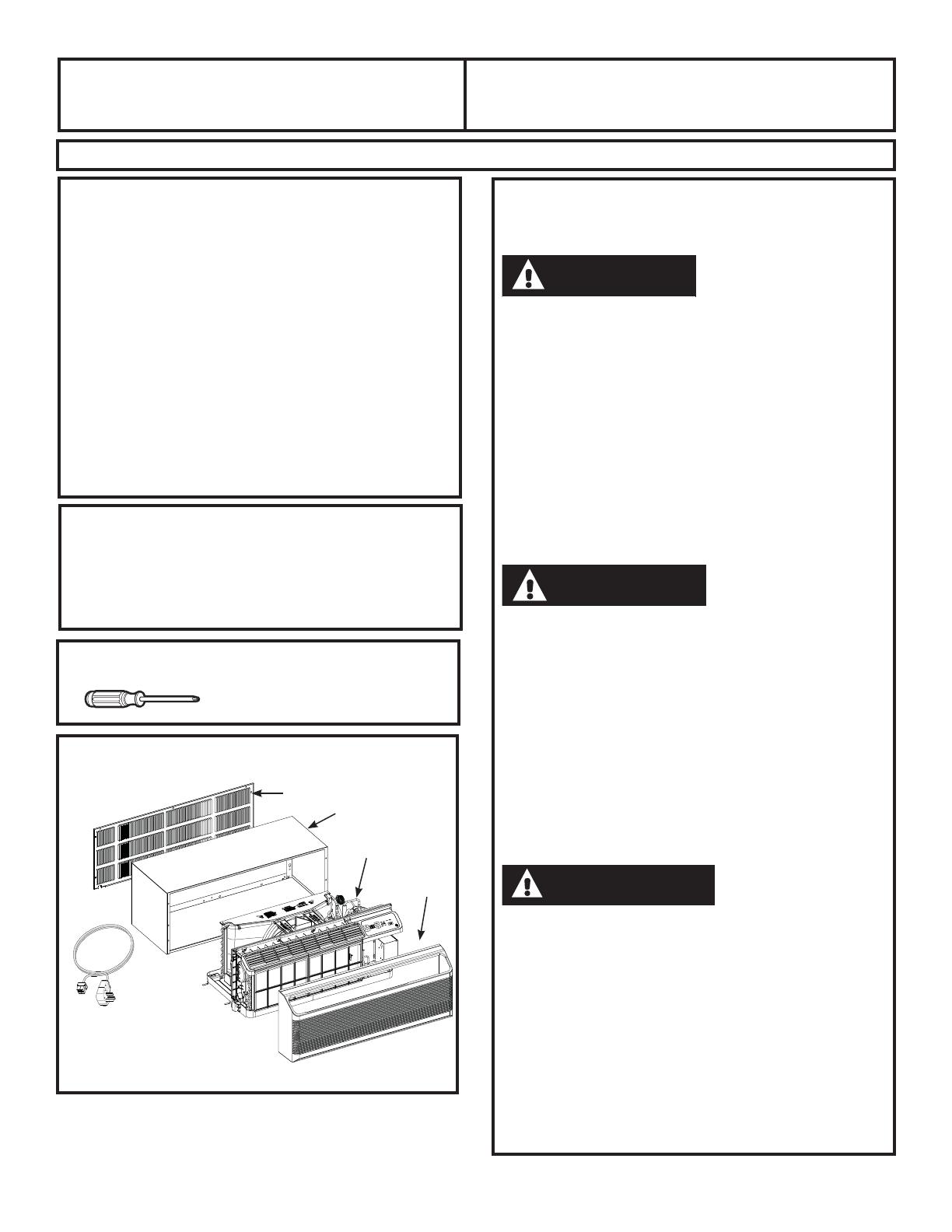
ZONELINE COMPONENTS
Appearance may vary.
** Shipped with the Zoneline unit
** Check the “Essential Elements” list
on the unit located on front of the
base pan
Exterior grille/louver**
Wall case**
Zoneline unit
Room
cover*
Power
supply kit**
CAUTION
ATTENTION
PRECAUCIÓN
14
Installation Instructions
Use the correct wall case
This unit is designed to be installed in a GE plastic or
insulated metal wall case. This minimizes condensation
from forming on the room side of the case.
NOTE: There are several extra holes in the unit side
flanges for installation in wall cases other than GE. To
avoid damaging the flange insulation, the installer should
use an awl or other sharp tool to puncture the insulation
in the appropriate holes before installing the attachment
screws.
Use the correct outdoor grille
You should use the outdoor grilles shown on the
“Essential Elements” label on the base pan.
If an existing grille is not replaced, capacity and
efficiency will be reduced and the unit may fail to
operate properly or fail prematurely. A deflector kit,
RAK40, may be used with grilles that were not designed
for your new GE Zonelines. The RAK40 contains air
deflectors and gaskets that mount to the unit to direct
the hot exhaust air away from the air intake to allow
the unit to function properly. The grille must have a
65% minimum free area (as calculated by ASHRAE).
See the Architects and Engineers Data Manual for more
detailed information.
Any vertical deflectors in a non GE existing rear
grille should be removed to decrease condenser air
recirculation that can cause the unit to “short-cycle”
and lead to premature component failure.
Use the correct power cord
Local codes may require the use of arc fault or leakage
current detection devices on 230/208-volt installations.
Replacing a ducted unit
New ducted installation:
If this unit is to be installed in a new ducted application
using a duct adapter kit, the kit must be installed before
the unit is placed in the wall case. The installation
instructions are packed with the kit.
Duct kits available:
RAK6053
RAK601B/602B
Existing ducted installation:
Replacement of an existing ducted unit may require
different components. Request this information from your
sales representative. Duct seals on existing unit need to
be removed and added to the new unit.
Replacing 230/208 volt units:
See page 16.
Replacing 265 volt units:
See page 17.
When using a duct kit, you must always turn Mode 7 to
ON “ See Mode instructions on page 9.
REPLACING AN EXISTING UNIT
Check the “Essential
Elements” label for
important information.
Duct
Case
Mounting
plate
Duct Mode
Shown ON
15
Installation Instructions
ELECTRICAL SUBBASE
CONNECTION
Power cords may include an arc fault interruption
or a leakage current detection interruption device.
A test and reset button is provided on the plug case
or the inline case. The device should be tested on
a periodic basis by first pressing the TEST button
and then the RESET button. If the TEST button does
not trip or if the RESET button will not stay engaged,
discontinue use of the Zoneline and contact a
qualified service technician.
Depending on application, a power supply kit with LCDI
must be used to supply power to the Zoneline unit. The
appropriate kit is determined by the voltage, the means of
electrical connection and the amperage of the branch
circuit.
Connections of 208 or 230-volt circuits may be with a
power supply kit or a junction box kit.
All wiring, including installation of the receptacle,
must be in accordance with the NEC and local codes,
ordinances and regulations. Codes require the use of
an arc fault or leakage current detection device on the
power cord except direct connect. Be sure to select the
correct cord for your installation.
Branch Circuit and Proper GE Power Cord
Unit Amperage Rating with LCDI Device
15 RAK315P
20 RAK320P
30 RAK330P*
230/208 VOLT ELECTRICAL CONNECTION OPTIONS
POWER
CORD CONNECTION
DIRECT CONNECTION
Order the following Kit for 230/208-volt direct
connection as required:
Review installation instructions provided with power
cord or direct connect kits for detailed assembly
instructions.
If using a sub-base connection, the RAK4002C Junction
Box is also necessary for a complete installation.
Branch Circuit and Proper GE
Unit Amperage Rating Subbase Kit
15 RAK204D15PA
20 RAK204D20PA
30 RAK204D30PA
Tandem
15 Amp
230/208 volt receptacle configuration
Perpendicular
20 Amp
Large Tandem
30 Amp
Branch Circuit and
Unit Amperage Rating
Power
Supply Kit
15 RAK315D
20 RAK320D
30 RAK330D
Power supply kit
(Appearance may vary)
230/208-volt models may be installed using one
of the following electrical subbases:
Electrical subbases provide an enclosure for direct
connection or enclosed receptacles. The subbase kit
includes the power cord.
The instructions provided with the selected subbase kit
must be carefully followed. It is the responsibility of the
installer to ensure the connection of components is done
in accordance with these instructions and all electrical
codes.
If using a sub-base connection, the RAK4002C Junction
Box is also necessary for a complete installation.
16
Installation Instructions
265 VOLT ELECTRICAL CONNECTION OPTIONS
Connection of this 265 V AC product to a branch circuit MUST
be done by direct connection in accordance with the National
Electrical Code. Plugging this unit into a building-mounted exposed
receptacle is not permitted by code.
These models must be installed using the appropriate GE power
supply kit for the branch circuit amperage and the electrical
resistance heater wattage desired. Use the POWER CONNECTION
CHART on page 18 to determine the correct kit required. One of
the following installation methods must be used:
Vous DEVEZ brancher ce produit alimenté par courrant alternatif
de 265 volts au circuit de dérivation par branchement direct
conformément au Code national d’électricité. Le Code n’autorise
pas le branche men td evotr eappareil à une prise exposée
montée sur le bâtiment.
Vous devez installer ces modèles à l’aide de la bonne trousse
d’alimentation électrique GE pour l’ampérage du circuit de
GpULYDWLRQHWODSXLVVDQFHGXFKDXȺDJHjUpVLVWDQFHpOHFWULTXH
désirée. Utilisez le Tableau de contact électrique, page 18, pour
déterminer la bonne trousse requise. Vous devez utiliser l’une des
méthodes suivantes d’installation.
La conexión de este producto de 265 voltios de CA a un circuito
derivado DEBE realizarse mediante una conexión directa de
acuerdo a las indicaciones del NEC. El código no permite enchufar
esta unidad a una caja externa.
Estos modelos deben instalarse utilizando el kit de GE de
suministro de energía adecuado para el amperaje de circuito
derivado y el vatiaje deseado para el calefactor de resistencia
eléctrica. Utilice la TABLA DE CONEXIONES ELÉCTRICAS en la
página 18 para determinar cuál es el kit necesario. Debe utilizarse
uno de los siguientes métodos de instalación.
A. FOR SUBBASE
INSTALLATION
Electrical subbase kits are available to provide a flexible
enclosure for direct connection.
The instructions provided with the selected subbase kit
must be carefully followed. It is the responsibility of the
installer to ensure the connection of components is done
in accordance with these instructions and all electrical
codes.
Branch Circuit and Proper GE Power
Unit Amperage Rating Subbase Kit Supply Kit
15 RAK204E15 RAK515P
20 RAK204E20 RAK520P
30 RAK204E30 RAK530P
B. FOR DIRECT CONNECT
INSTALLATION
If an electrical subbase is not used, direct connection to
branch circuit wiring inside the provided junction box must
be done in accordance with the following steps.
Order the following Kit for 265-volt direct connection
as required:
Review installation instructions provided with power
cord or direct connect kits for detailed assembly
instructions.
Branch Circuit and Power
Unit Amperage Rating Supply Kit
15 RAK515D
20 RAK520D
30 RAK530D
WARNING
AVERTISSEMENT
ADVERTENCIA
17
Installation Instructions
POWER CONNECTION CHART
Power Cord Connections
Direct Connections
230/208 Volt
Power Supply Kits
with Current Leakage
Detection Device (1)
Wall Plug
&RQ¿JHUDWLRQ Circuit Protective Device
Heater Wattage
@ 230/208 Volts
RAK315P/SP
RAK320P/SP
RAK330P/SP
Tandem
Perpendicular
Large Tandem
15-Amp Time-Delay Fuse or Breaker
20-Amp Time-Delay Fuse or Breaker
30-Amp Time-Delay Fuse or Breaker
2.40/1.96 KW
3.40/2.78 KW
4.80/3.93 KW (High Fan)
3.80/3.11 KW (Low Fan)
230/208 Volt
Power Supply Kits (2)
Circuit Protective Device Heater Wattage
@ 230/208 Volts
RAK315D
RAK320D
RAK330D
15-Amp Time-Delay Fuse or Breaker
20-Amp Time-Delay Fuse or Breaker
30-Amp Time-Delay Fuse or Breaker
2.40/1.96 KW
3.40/2.78 KW
4.80/3.93 KW (High Fan)
3.80/3.11 KW (Low Fan)
265 Volt
Power Supply Kits
Circuit Protective Device Heater Wattage
@ 265 Volts
RAK515D
RAK520D
RAK530D
15-Amp Time-Delay Fuse or Breaker
20-Amp Time-Delay Fuse or Breaker
30-Amp Time-Delay Fuse or Breaker
2.40 KW
3.40 KW
4.80 KW (High Fan)
3.8 KW (Low Fan)
(1) A junction box is included with SP kits.
(2) A junction box is included with these kits.
18
Installation Instructions
1. INSTALL THE WALL CASE
AND EXTERIOR GRILLE
The RAB71A/B series or RAB77A4/77B wall case must be
properly installed per instructions packed with the case.
Remove the corrugated stiffener and the outdoor
protective panel. Use the slit in the outdoor panel
as a handhold and push out.
Install the exterior grille from the room side following
instructions packed with the grille.
NOTE: For installation with a subbase or duct adapter,
see the instructions packed with those kits.
2. PREPARE THE UNIT
Carefully remove the foam shipping blocks from the
room front, compressor and outdoor fan. There may
be multiple blocks and pieces of shipping tape that
need to be removed.
Remove the room cover by pulling it out at the bottom
to release it (1); then lift it up to clear the rail along the
unit top (2).
If vent door is to be operational, remove shipping
screws from the front side of the vent door, if present.
INSTALLING THE ZONELINE
Shipping tape
(Locations may vary)
Remove the
shipping screws
(if operation is
desired)
Stiffener
Protective
panel
Slit
19
Installation Instructions
INSTALLING THE ZONELINE (cont.)
3. INSTALL THE UNIT INTO
THE WALL CASE
Slide the unit into the wall case and secure with four
screws through the unit flange holes.
The four screws will be located in a sealed bag that
sits under the control panel, sitting in the pocket in the
basepan.
5. REPLACE THE ROOM
FRONT
Reinstall the room cover by aligning and placing the top
rail of the room cover over the chassis (1), then pushing
it in at the bottom (2).
NOTE: There are several extra holes in the unit side
flanges for installation in wall cases other than GE.
To avoid damaging the flange insulation, the installer
should use an awl or other sharp tool to puncture the
insulation in the appropriate holes before installing the
attachment screws.
The four wall case screws will be taped
to the pocket in front of the control box.
4
. CONNECT POWER CORD
OR DIRECT CONNECT KIT
Review installation instructions provided with power
cord or direct connect kits for detailed assembly
instructions.
Power supply kit
(Appearance may vary)
20
  • Page 1 1
  • Page 2 2
  • Page 3 3
  • Page 4 4
  • Page 5 5
  • Page 6 6
  • Page 7 7
  • Page 8 8
  • Page 9 9
  • Page 10 10
  • Page 11 11
  • Page 12 12
  • Page 13 13
  • Page 14 14
  • Page 15 15
  • Page 16 16
  • Page 17 17
  • Page 18 18
  • Page 19 19
  • Page 20 20
  • Page 21 21
  • Page 22 22
  • Page 23 23
  • Page 24 24
  • Page 25 25
  • Page 26 26
  • Page 27 27
  • Page 28 28

GE AZ45E09DAP Owner's Manual and Installation Instructions

Type
Owner's Manual and Installation Instructions

Ask a question and I''ll find the answer in the document

Finding information in a document is now easier with AI