Page is loading ...

-1-
IMPORTS, INC.
GEAR HEAD MILL / DRILL
MODEL G1126
INSTRUCTION MANUAL
COPYRIGHT © 1994 BY GRIZZLY IMPORTS, INC.
WARNING: NO PORTION OF THIS MANUAL MAY BE REPRODUCED IN ANY
SHAPE OR FORM WITHOUT THE WRITTEN APPROVAL OF GRIZZLY IMPORTS, INC.
PRINTED IN USA, SEPTEMBER, 1994

-2--2-

-3-
TABLE OF CONTENTS
PAGE
I. INTRODUCTION ......................................................................................................................1
II. COMMENTARY........................................................................................................................1
III. SAFETY RULES FOR ALL TOOLS ........................................................................................2
IV. UNPACKING ............................................................................................................................4
V. PIECE INVENTORY ................................................................................................................4
VI. CLEAN-UP BEFORE ASSEMBLY ..........................................................................................5
VII. SITE PLANNING......................................................................................................................5
A. FLOOR LOAD........................................................................................................................5
B. WORKING CLEARANCES ....................................................................................................5
VIII. ELECTRICAL SERVICE REQUIREMENTS ............................................................................6
A. GENERAL..............................................................................................................................6
B. GROUNDING ........................................................................................................................6
IX. ASSEMBLY..............................................................................................................................7
A. POWER FEED ......................................................................................................................7
B. HANDWHEELS ....................................................................................................................9
C. CUTTER / ARBOR INSTALLATION ....................................................................................9
X. OPERATION............................................................................................................................10
A. TABLE ................................................................................................................................10
B. POWER FEED ....................................................................................................................10
C. COLUMN HEIGHT ..............................................................................................................11
D. SPINDLE SPEED................................................................................................................12
E. ON/OFF & FORWARD /REVERSE SWITCHING ..............................................................12
F. SPINDLE HEIGHT ..............................................................................................................13
G. DOWNFEED LIMITER ........................................................................................................13
H. HEAD ROTATION ..............................................................................................................14
I. GIB & LEADSCREW ..........................................................................................................14
XI. EQUIPMENT MAINTENANCE ..............................................................................................15
XII. CLOSURE ............................................................................................................................15
XIII. MACHINE DATA....................................................................................................................16
XIV. WARRANTY AND RETURNS................................................................................................17
XV. PARTS DIAGRAMS ..............................................................................................................18
A. HEAD PARTS DIAGRAM....................................................................................................18
B. TABLE PARTS DIAGRAM ..................................................................................................19
XVI. PARTS LIST ..........................................................................................................................20
COPYRIGHT © 1994 BY GRIZZLY IMPORTS, INC.
WARNING: NO PORTION OF THIS MANUAL MAY BE REPRODUCED IN ANY
SHAPE OR FORM WITHOUT THE WRITTEN APPROVAL OF GRIZZLY IMPORTS, INC.
PRINTED IN USA, SEPTEMBER, 1994

-4 -

I. INTRODUCTION
We are proud to offer the Model G1126 Gear-Head Mill / Drill. The Model G1126 is part of a grow-
ing Grizzly family of fine metalworking machinery. When used according to the guidelines described
in this manual, you can expect years of trouble-free, enjoyable operation and proof of Grizzly’s com-
mitment to customer satisfaction.
The Model G1126 is ideal for use in a small-to-medium sized machine shop or by the serious home
craftsman. This mill / drill features a 1
1
/
2 H.P., 110/220V single-phase motor. The Model G1126’s pre-
cision gearbox and full reversing capabilities give it six working speeds in either spindle direction.
The Model G1126 features a big 9
1
/2" x 32" table, which rides on wide precision dovetails, giving
smooth and solid movement.
A number of accessories for the Model G1126, including an optional flycutter and a 52-pc. clamping
kit, are available through the Grizzly catalog.
We are also pleased to provide this instructional manual with the Model G1126 Gear-Head Mill / Drill.
This manual was written to guide you through assembly, review safety considerations and cover
general operating procedures. It represents our latest effort to produce the best documentation pos-
sible. If you have any constructive criticisms or comments you feel we should include in our next
printing, please write us at the address below.
Manager, Technical Documentation
Grizzly Imports, Inc.
P.O. Box 2069
Bellingham, WA 98227
Finally, we stand behind our machines. We have two excellent regional service departments at your
disposal, should the need arise. If you have any service questions or parts requests, please call or
write us at the location listed below.
Grizzly Industrial, Inc.
1203 Lycoming Mall Circle
Muncy, PA 17756
Phone: (570) 546-9663
Fax: (800) 438-5901
E-Mail: [email protected]
Web Site: http://www.grizzly.com
II. COMMENTARY
To operate this, or any power tool, safely and efficiently, it is essential to become as familiar with its
characteristics as possible. Take as much time as necessary to become acquainted with the Model
G1126 Mill / Drill. The time you invest before you begin to use this machine will be time well spent.
Also, read all of the safety procedures. If you do not understand something, do not operate this
machine.
- 1 -

- 2-
The specifications, drawings and photographs in this manual represent the Model G1126, as sup-
plied when the manual was prepared. However, owing to Grizzly’s policy of continuous improve-
ment, changes to the Model G1126 may be made at any time with no obligation on the part of
Grizzly.
The information in this manual has been obtained from sources believed to be reliable and as up-to-
date as possible. While this manual is intended to be a good source for basic information, it is by no
means the last word on milling or metalworking. Instead, we have focused primarily on the proper
assembly and adjustment of the machine. We have also included some important safety measures
which we believe to be essential to this machine’s operation. Though most safety measures are gen-
erally universal, Grizzly cautions that each workshop is different and safety rules should be consid-
ered as they apply to your individual situation.
The Model G1126 is designed for highly-skilled individuals who have an understanding of metals and
machining. A strong knowledge of metalworking is essential for the proper use of the mill / drill. We
realize there are numerous kinds of cutters and specialized techniques used in metalworking. To list
all of the techniques necessary to operate a mill / drill correctly for specific applications would require
many volumes.
If you are not familiar with milling machines and their safe operation, we strongly suggest you obtain
as many books on the subject as you can. A visit to the local library, or time spent browsing through
back issues of machinist’s magazines will prove beneficial in gaining knowledge of mill / drill opera-
tions.
III. SAFETY RULES FOR ALL TOOLS
WARNING! As with all power tools, there is a certain amount of danger associated with the Model
G1126 Gear-Head Mill / Drill. Using the tool with respect and caution will considerably lessen the
possibility of mechanical damage or operator injury. However, if normal safety precautions are over-
looked or ignored, injury to the operator or others in the area is possible.
There are certain applications for which this tool was designed. We strongly emphasize that this tool
should never be modified and/or used for any application other than that for which it was designed.
If you are confused about any aspect of this machine, do not use it until you have resolved any
questions you might have. The following are important safety rules for all tools:
1. KNOW YOUR POWER TOOL. Read the owner’s manual carefully. Learn the tool’s applications
and limitations, as well as its particular hazards.
2. KEEP GUARDS IN PLACE and in working order.
3. GROUND ALL TOOLS. If the tool is equipped with a three-prong plug, it should be plugged into
a three-hole grounded outlet. If an adapter is used to accommodate a two-prong receptacle, the
adapter plug must be attached to a known ground. Never remove the grounding prong.
4. REMOVE ADJUSTING KEYS AND WRENCHES. Make it a habit to ensure keys and adjusting
wrenches are removed from the machine before turning it on.
- 2 -

- 3 -
5. KEEP WORK AREA CLEAN. Cluttered areas and benches invite accidents.
6. AVOID DANGEROUS ENVIRONMENTS. Do not use power tools in damp or wet locations or
expose them to rain. Keep your work area well lighted.
7. KEEP CHILDREN AND VISITORS AWAY. All children and visitors should be kept a safe dis-
tance away from your work area.
8. MAKE WORKSHOP CHILD-PROOF with padlocks, master switches, or by removing starter
keys.
9. DO NOT FORCE TOOL. Tools work better and more safely when they are allowed to work at
their own speed.
10. USE THE RIGHT TOOL. Do not use a tool or an attachment to do a job it wasn’t intended for.
11. WEAR PROPER APPAREL. Do not wear loose clothing, gloves, neckties, or jewelry that might
get caught in moving parts. Non-slip footwear is also recommended. Wear a hat or other pro-
tective head wear if your hair is long.
12. USE SAFETY GLASSES AND EAR PROTECTION. Also use a dust mask if the cutting oper-
ation creates dust or fumes.
13. SECURE YOUR WORK. Use clamps or a fixture to hold your work. It is safer than using your
hands and frees up both hands for operating the tool.
14. DO NOT OVERREACH. Keep proper footing and balance at all times.
15. MAINTAIN TOOLS IN TOP CONDITION. Keep tools sharp and clean for best and safest per-
formance. Follow instructions for lubricating and changing accessories.
16. DISCONNECT TOOLS FROM POWER before servicing and when changing accessories, such
as blades, bits and cutters.
17. USE RECOMMENDED ACCESSORIES. Consult the current catalog for recommended acces-
sories. The use of improper accessories may be hazardous.
18. AVOID ACCIDENTAL STARTING. Make sure the switch is in the “OFF” position before plug-
ging in the cord.
19. NEVER STAND OR LEAN ON TOOL. Serious injury could occur if the tool is tipped or if the
cutting tool is accidentally contacted.
20. CHECK DAMAGED PARTS. Before further use of the tool, any part or guard that is damaged
should be promptly repaired or replaced. Do not operate the machine until you are certain it is
in perfect running condition. Failure to follow this precaution could result in further mechanical
damage and operator injury.
21. DIRECTION OF FEED. Always feed your work against the direction of blade or cutter travel.
Workpieces fed in the same direction as the cutter travel could be forced out of your control.

- 4 -
V. PIECE INVENTORY
Take a quick inventory of the parts and put them aside for assembly later.
Since the majority of the Model G1126 is pre-assembled at the factory, there aren’t a lot of items to
inventory. You should have the following:
• Mill / Drill Unit
• Power Feed
• Fly Cutter
• Handwheels
• Adjustment Wrench
• Flycutter
• Drill Chuck Arbor
• Quill Feed Rods (3 pcs.)
•
1
/2" Drill Chuck and Key
22. NEVER LEAVE THE TOOL RUNNING UNATTENDED - TURN POWER OFF. Do not leave the
tool until it comes to a full stop.
23. DRUGS, ALCOHOL, MEDICATION. Do not operate the tool under the influence of drugs, alco-
hol, or any medication. Never operate machinery when overly fatigued.
IV. UNPACKING
The Model G1126 comes from the factory in a wooden crate. While it is still on its pallet, use a fork-
lift (if available) to move the machine to its permanent location. Once in place, carefully remove the
crate surrounding the Model G1126 with a hammer or crowbar. Lift the Model G1126 with a sling
wrapped around the milling head to lift the machine off the pallet and onto your bench. Make sure
you tighten all the locks that restrict moving parts to avoid sudden shifts which could unbalance the
machine.
REMEMBER: Always wear ANSI-approved safety glasses when uncrating equipment.
If you find the machine is damaged after you’ve signed for delivery and the truck and driver are
already gone, you will need to file a freight claim with the carrier. Save the containers and all pack-
ing materials for inspection by the carrier or their agent. Without the packing materials, filing a freight
claim can be difficult. If you need advice regarding this situation, please call us.
Caution: The mill / drill weighs a hefty 660 pounds in its packaging. DO NOT attempt to move this
machine without proper lifting equipment.

- 5 -
VI. CLEAN-UP BEFORE ASSEMBLY
All of the unpainted surfaces on this machine – and a few of the painted ones – are coated with a
preservative oil, called Cosmolene, which prevents rust and corrosion during shipping. The coating
can be removed with paint thinner (mineral spirits) and a good supply of paper towels, although you
may find that careful scraping with a putty knife or plastic spatula may be necessary where the coat-
ing is particularly thick. Use caution when removing the coating with your putty knife to avoid scratch-
ing the table top or painted surfaces on the machine.
DO NOT use gasoline, lacquer thinner, acetone, or other highly-flammable solvents. The possibility
of flash fire or explosion is far greater and they don’t work much better anyway. Don’t use chlorinat-
ed solvents, such as perchloroethelene; they will lift the paint and ruin the mill / drill’s finish. Be care-
ful when working around the drive belts. Any solvent that cuts grease will, in the long run, be harm-
ful to rubber. While you are cleaning the mill / drill, please pay attention to the following rules:
1. Work only in a well-ventilated area.
2. Make sure there are no sources of open flame in your work area, such as pilot lights or wood-
stoves.
3. DO NOT smoke while you’re working.
4. Dispose of soiled towels in a proper manner to avoid fire and environmental damage.
You may find some other small parts also covered with Cosmolene. The smaller pieces are best
cleaned by placing them in a container of solvent for several minutes. After soaking, the remaining
coating may be removed with firm pressure, using rags or paper towels. Some pieces may have to
be pried apart using a putty knife. Once again, dispose of waste properly.
VII. SITE PLANNING
When placing the Model G1126 in your shop, three considerations should be addressed; floor load,
working clearances and electrical requirements. We’ll look at the first two requirements now and
leave the third for the next section.
A. FLOOR LOAD
Your Model G1126 represents a fairly large weight load in a small footprint. For planning purposes,
the intended workbench should be able to take a uniform distributed live load of 175 pounds per
square foot. Most commercial and residential floors are suitable for the Model G1126, though some
older wooden residential floors may require some additional build up to support the machine, the
bench and the operator.
B. WORKING CLEARANCES
Working clearances will vary from one customer to the next, depending on individual requirements.
Place your Model G1126 in a position that can handle your most ambitious working requirements.
The working area around the Model G1126 should be lit well enough to eliminate shadows.

- 6 -
VIII. ELECTRICAL SERVICE REQUIREMENTS
The Model G1126 is furnished with a complete electrical package: A 1,720 RPM 1
1
/
2 H.P. motor, ON-
OFF starter switch, FORWARD/REVERSE switch and a cord set. The motor is single phase and can
be wired for 110V or 220V. As delivered, the G1126 is ready for 110V operation. If you want 220V
operation, the wiring system must be changed for the desired voltage.
A. GENERAL
The Model G1126 comes with a standard 110V cord and plug. Under extreme load, the Model
G1126’s motor could draw a potential 22 amps. Yet under the majority of circumstances, the Model
G1126 should work satisfactorily when connected to its own dedicated 20-amp circuit.
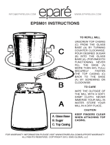
If you choose to re-wire the Model G1126 for 220V operation, use NEMA-approved connecter plugs.
See Figure 1 for examples of typical plug configurations. You should also check with our service
department for specific information on motor re-wiring requirements. Your local building
department or a licensed electrical contractor should also be able to help you if electrical require-
ments exceed your understanding.
Figure 1
If you are plugging into an existing outlet, ensure that it is grounded. If not, it will be necessary to run
a separate grounding wire, #10 copper or larger, from the frame of the machine to the grounding stud
at your service panel.
If you find it necessary to use an extension cord with the Model G1126, make sure its conductors
are rated at #10 or larger (for 220V). The cord should be rated for hard service (S-type jacket), with
NEMA-approved connectors and a ground wire. An SJ-rated cord (#12-wire) should be sufficient for
110V.
CAUTION: Never cut the grounding pin from the plug. If you have problems with the electrical equip-
ment supplied with the Model G1126, please contact our service department for assistance.
B. GROUNDING

- 7-
- 7 -
IX. ASSEMBLY
Figure 2
The Model G1126 is largely pre-assembled at the factory, so very little actual assembly is required.
The motor is already mounted and all wiring is in place. The remaining parts which require assem-
bly are:
A. Power Feed
B. Handwheels
C. Cutter / Arbor Installation
The necessary assembly can be accomplished with a few hand tools. You’ll need a 12mm wrench,
a 14mm wrench, metric Allen wrenches and a Phillips head screwdriver. An adjustable wrench and
a metric socket set are helpful, but not essential, for assembly.
Spindle Height
Adjustment
Lever Lock
Front-to-Back
Adjustment
Handwheel
Power
Feed
Column
Adjustment
Quill
Return
Spring
Side-to-Side
Adjustment
Handwheel
Speed
Selectors
Power / Direction
Switch
Spindle Height
Adjustment
Wheel
Micro Height
Adjustment
Wheel
Head Swivel
Adjustment
Bolts
Power Feed
Stops
A. POWER FEED
The Model G1126 features a 110V auto-feed mechanism, allowing hands-free side-to-side passes
while milling. The variable-speed feed control ensures greater consistency when milling large, flat
surfaces. To install the auto-feed mechanism:
1. Attach the drive gear to the end of the table screw, using the attached setscrew. The gear cou-
plers will lock in place with the matching coupler on the end of the table screw.
2. Attach the clamping bracket provided with the auto-feed mechanism, as shown in Figure 3.
Gib Locks

-8 -
-8-
3. When the auto feed and the clamping bracket are secured together, set the assembly on the
end of the table, so the gears mesh. The clamping bracket will fit over the top of the table, allow-
ing the bolts on the inboard side of the bracket to be tightened against the table’s cast iron sur-
face. Mark the point on the table’s trough where the mounting bolts contact the table and spot
drill to give the mounting bolts a surface to “bite” without slipping on the rough cast surface.
Figure 3
4. Replace the center travel stop at the front of the table with the microswitch. The switch, when
used with the adjustable stops, automatically limits table movement.
Caution: Before operating the Model G1126, make sure the placement of the auto feed’s power
cord and the control cord for the microswitch are both clear of any movements which could pinch or
crush either cord. Before operating the power feed, mark the maximum distance the table can move
before the power feed comes in contact with the machine’s base. Use that as a reference mark each
time you re-adjust your table stops to avoid possible damage to the power feed.
NOTE: Use care when aligning the leadscrew gears with the gearing on the power feeder. The fit is
correct when you can just slightly wiggle one gear without moving the other. If there is too much
space between the gears, teeth can be stripped under heavy loads. If the teeth mesh too tightly, the
supporting bearings in the power feeder will wear out prematurely.
An alternative method for attaching the power feed is to eliminate the clamping bracket and mount
the power feed directly to the table. As with the other method, you want to be certain that the gears
are properly aligned. Once aligned, mark, drill and tap holes in the end of the table casting. Bolt the
power feed to the casting.
In many ways, this method of attachment is much better than the other method. The removal of the
clamping bracket provides more secure mounting and provides a greater area of flat table space.

-9 -
-9-
B. HANDWHEELS
When the auto-feed mechanism is in place, attach the handwheel to the other end of the leadscrew.
The handwheel coupling will lock, like the auto-feed mechanism, with the coupling on the leadscrew.
Tighten the setscrew once the handwheel is in place.
Attach the other handwheel to the leadscrew at the front of the base casting. When the handwheel
locks in place, tighten the setscrew.
C. CUTTER / ARBOR INSTALLATION
The Model G1126 features an R-8 spindle which accepts all industrial collets and arbors. To install
a collet or arbor:
1. Remove the spindle cap from the top of the mill head.
2. Insert the collet or cutting tool’s arbor in the spindle housing, making sure to line up the keyway
with the matching pin in the spindle opening.
3. Turn the hex head at the top of the drawbar clockwise until the threads at the bottom of the
drawbar mesh with the female threads in the top of the collet or arbor. See Figure 4.
4. If you’re using a collet with a bit or cutting tool, place the bit in the hole at the bottom of the col-
let and continue to tighten the drawbar until both the collet and bit are tightly in place.
Figure 4
To remove a collet or arbor:
1. Loosen the drawbar (2 or 3 turns).
2. Tap on the top of the drawbar with a mallet. See Figure 5.
3. Once the collet or arbor is loosened from the taper, continue to turn the drawbar counterclock-
wise until the drawbar and the female threads of the arbor or collet are unattached. Hold the
collet or arbor as you loosen the drawbar. Once loose, remove and replace with your desired
cutter. Remove cutting tools from arbor when not in use.
Figure 5

-1 0 -
-10-
B. POWER FEED
X. OPERATION
The bench-mounted Model G1126 Gear-Head Mill / Drill is a fundamental metalworking machine
capable of most standard milling and drilling operations. In order to effectively use the machine, it’s
necessary to understand the various adjustments the Model G1126 features. This section deals with
the specific adjustments required to operate the Model G1126.
A. TABLE
The Model G1126’s table rides on precision dovetail ways. Adjustment from side to side is accom-
plished by turning the handwheel at the end of the table, or by using the power feed. Movement from
front to back is controlled by the handwheel at the front of the machine’s base. The mill / drill’s tables
can be locked to eliminate unwanted movement in either direction by using the locking levers locat-
ed just below the table. The side-to-side locks are located on either side of the power feed
microswitch. The locks restricting movement from front to back are located on the drill / mill’s base,
just below the table. See Figure 6.
Figure 6
The table on your G1126 Gear-Head Mill / Drill is equipped with
1
/2" T-slots, which allow you to
mount fixtures, such as vises, rotary tables and dividing heads to your machine. The T-slots are
designed to accept
1
/2" T-bolts to anchor the optional equipment mentioned above. Keep in mind that
T-bolts are measured at the thread, not at the head, so you’ll want to use care when sizing T-bolts
for use with the Model G1126. See Figure 7 for specific measurements.
Figure 7
1
1
/
16"
5
/8
"
7
/
16"
7
/
16"
7
/
8"
The power feed supplied with your Model G1126 features a variable speed control, which allows
you to adjust feed speed to fit specific materials you choose to mill. The power feed is activated by
a switch mounted on the outboard end of the power feed gearbox.
A microswitch mounted on the front of the table casting allows you to limit table travel and also func-
tions as an “auto pilot” for hands-free multiple passes.

-1 1 -
-11-
C. COLUMN HEIGHT
The Model G1126 is capable of reaching a maximum spindle-to-table distance of 18
1
/2", making it
an ideal choice for a wide variety of milling operations. Column height is adjusted by a large crank
handle on your left side, when facing the front of the machine. To make height adjustments:
1. Loosen the two clamping nuts at the back of the mill head body with the lug wrench provided.
See Figure 8.
2. Turn the cranking handle clockwise to raise the mill head or counterclockwise to lower it, until
you reach the proper height for your project.
3. Re-tighten the clamping nuts.
4. Ensure that the lug wrench is removed from the machine before proceeding with milling oper-
ations.
Figure 8
REMEMBER: The mill head can be top-heavy in its fully-raised position. Be sure to mount the Model
G1126 securely to your bench. Always make sure the clamping nuts are tightly secured before oper-
ating this machine.
Tilting Lock
Clamping
Nuts
Establishing proper speeds for you power feed is just part of a complex equation that encompass-
es a number of variables, including; spindle speed, metal hardness, feed rate, cutting depth and cut-
ter type. Because of the complexity of the equations necessary to determine optimum spindle
speeds and feed rates, we suggest you obtain one of many good machinist’s guides on the market.
Community colleges and vocational schools are often good places to obtain informative textbooks
which go into the necessary mathematics of machining in detail.
A number of fine consumer publications dealing specifically with metalworking and machining are
also readily available. Check your local library or newsstand for availability in your area.

-1 2 -
-12-
Gear Ranges – Model G1126
D. SPINDLE SPEED
The Model G1126 features an internally-geared head which offers six speeds, both in forward and
reverse. Speed selection levers are located on the front of the mill head. See the chart below for
specific spindle speeds in each gear range.
Levers L1 L2 L3 H1 H2 H3
Spindle RPM 60 130 230 450 800 1500
REMEMBER: Do not attempt to change gear speeds while the machine is running. Allow all mov-
ing parts to come to a full stop before making any adjustments.
E. ON/OFF AND FORWARD/REVERSE SWITCHING
A 3-way toggle switch located on the front of the mill head controls both power and spindle direc-
tion. Always make sure the cutter is rotating in the direction required by your cutting tool. While most
bits and cutters are designed to operate in a clockwise rotation, some are designed to work coun-
terclockwise. Make sure the spindle direction is correct for your application.
CAUTION: Do not reverse the spindle direction while the machine is running. Allow the machine to
come to a full stop before changing directions.
CAUTION: Even at low spindle speeds, metal fragments from the cutting process can be expelled
by the mill / drill. Always wear ANSI-approved eyewear and protective clothing when operating the
Model G1126. Be sure that all observers are safely away from the machine while it is being operat-
ed.
Establishing proper spindle speed is just part of the same complex equation that determines power
feed rates. Like we noted before, the equation encompasses a number of variables, including; spin-
dle speed, metal hardness, feed rate, cutting depth and cutter type. Because of the complexity of
the equations necessary to determine optimum spindle speeds and feed rates, we suggest once
again you obtain one of many good machinist’s guides on the market. Community colleges and
vocational schools are often good places to obtain informative textbooks which go into the neces-
sary mathematics of machining in detail.

-1 3 -
-13-
Figure 9
G. DOWNFEED LIMITER
The downward movement of the spindle assembly can be limited by using the adjusting knob
mounted on the forward portion of the feed base, just below the depth stop gauge on the front of the
mill head. See Figure 10. Limiter distance can be set by using the indicator on the front of the milling
head.
Figure 10
F. SPINDLE HEIGHT
The Model G1126 uses rack-and-pinion gearing to control spindle height adjustment. The operator
has two options for adjustment – a 3-handled downfeed control and a handwheel-operated micro
adjustment control. See Figure 9.
To operate the micro-adjustment handwheel, tighten the locking knob on the 3-handled downfeed
control. Once locked, the adjustment of spindle height will be transferred to the handwheel.
The calibration dial can be adjusted for individual applications by loosening the setscrew on the
knurled surface and turning the indicator to “zero out” the dial. Once in place, tighten the setscrew.
A certain amount of backlash or play is typical in pinion gearing so keep in mind, while setting the
measurement dial, to make your adjustments while there is downward pressure against the micro
adjustment handwheel.

-1 4 -
-14-
H. HEAD ROTATION
The milling head on the Model G1126 is designed to swing up to 90° either left or right at the mill
head, enabling it to perform tasks such as angled drilling or horizontal slotting. To rotate the head:
1. Loosen the lock nuts on either side of the milling head. See Figure 11.
NOTE: Make sure to provide support for the milling head so it doesn’t unexpectedly rotate on its
own. Always maintain control of the milling head.
2. Rotate the milling head to its desired position, using the reference guides provided on the right
side of the machine.
3. Once in place, re-tighten the locking nuts.
Figure 11
Keep in mind that the head must be dialed in when it’s returned to the “zero” position if high levels
of accuracy are required. If you are able to use an angled vise to accomplish your milling operation
without tilting the milling head, you will save yourself a good amount of set-up time.
I. GIB AND LEADSCREW
After sustained use, the table on your Model G1126 may develop excessive play in the gibs and/or
in the leadscrews. Keep in mind that some play is normal, particularly in the leadscrews. But, should
you find the need to make adjustments, use the following guidelines:
The gibs are easily tightened by turning the large slotted screwheads in the front and right side of
the table base until you feel a slight drag when you turn the handwheels. The screw at the front of
the machine affects movement from front to back, while the screw under the right side of the table
affects longitudinal movement. You can loosen the screws if your table seems excessively stiff.
The leadscrew adjusters require a bit more effort. To adjust leadscrew tightness from front to back,
it’s necessary to provide access to the underside of the base. A hole in the bench under the Model
G1126’s base will make adjustment fairly simple. The adjuster can be found midway along the lead-
screw, inside the base. To eliminate excess leadscrew movement tighten the Allen head setscrew

-1 5 -
-15-
on the adjuster midway along the leadscrew. The longitudinal leadscrew adjuster can be tightened
with a long Allen wrench reached under the table. Once again, the setscrew in the tension adjuster
is located just above the longitudinal leadscrew. These adjusters may require you to fabricate
extensions for your hex wrenches. Make adjustments in small increments. Over-adjustment can add
unnecessary wear to both the leadscrews and the adjusters.
XI. EQUIPMENT MAINTENANCE
Your Model G1126 Gear Head Mill / Drill requires very little maintenance. A thorough cleaning, now
and again, will increase the machine’s durability and efficiency, by removing dust and grime that can
gum up moving parts. Sharp cutters are essential for top performance. If you find that the machine
cuts less efficiently than usual, inspect the cutters and repair or replace them as necessary. An
occasional application of a protective spray coating will keep the Model G1126’s table and other
bare metal parts from rusting and pitting.
REMEMBER: When performing maintenance or repairs on shop equipment, always disconnect the
machine from its power supply.
The Model G1126 features factory-sealed bearings. A sealed bearing requires no lubrication during
its lifetime. Should a bearing fail, your mill / drill will probably develop a noticeable rumble, which will
increase when the machine is put under load. If allowed to get worse, overheating of the journal con-
taining the bad bearing could occur. If the bad bearing is not replaced, it will eventually seize – pos-
sibly doing damage to other parts of the machine. Bearings are standard sizes and can be replaced
through Grizzly.
Points requiring periodic lubrication are:
1. The internal spline drive assembly. Insert top-quality non-hardening grease into the hole at the
top of the spindle pulley spline once every six months.
2. The main column. A light film of oil will smooth action and prevent rust and corrosion.
3. The quill. A light coating of oil will ensure smooth movement.
4. The quill return spring. Oil annually with a light lubricant (SAE 20). Apply with a brush or squirt
can.
5. The gear box. Replace lubricant annually with non-detergent SAE 30 oil.
6. The quill pinion. Lubricate every 90 days with non-hardening grease.
Note: Use care when performing maintenance. Never attempt maintenance procedures on the
machine while it’s running.
XII. CLOSURE
The following pages contain the directory of parts for your Model G1126. Please feel free to write or
call us if you have any questions about the machine or the manual. Thanks again for your business
and continued support. We look forward to serving you again soon.

- 16 -
XIII. MACHINE DATA
GRIZZLY MODEL G1126 GEAR-HEAD MILL / DRILL
Design Type ..................................................................................................................Bench Model
Overall Dimensions:
Height ....................................................................................................................................52
1
/2"
Length....................................................................................................................................31
1
/
2"
Width ......................................................................................................................................47
1
/2
"
Column Diameter ....................................................................................................................4
1
/
2"
Table Size ......................................................................................................................9
1
/2" x 32"
T-Slot Size..................................................................................................................................
5
/
8"
Quill Diameter..............................................................................................................................3"
Spindle Taper............................................................................................................................R-8
Weight (Shipping) ..............................................................................................................660 lbs.
Weight (In Place) ..............................................................................................................594 lbs.
Construction ........................................................................................................................Cast Iron
Capacities:
Drilling ......................................................................................................................................1
1
/2"
Face Milling ................................................................................................................................3"
End Milling ..............................................................................................................................4
1
/
4"
Swing ........................................................................................................................................21"
Max Distance Spindle to Table..............................................................................................18
1
/2"
Spindle Stroke ............................................................................................................................5"
Head Rotation (On Column) ..................................................................................................360°
Head Swivel ..........................................................................................................................180°
Longitudinal Travel....................................................................................................................24"
Cross Travel................................................................................................................................9"
Spindle Speeds (RPM) ....................................................................60, 130, 230, 450, 800, 1500
Motor:
Horsepower ......................................................................................................................1
1
/2 H.P.
Phase / Voltage ............................................................................................Single Phase / 110V
Amps ..........................................................................................................................................12
Cycle and RPM ..................................................................................................60 HZ/1720 RPM
Bearings ............................................................................Shielded and Lubricated-For-Life / Ball
Power Transfer................................................................................................................Belt Drive
Specifications, while deemed accurate at the time of publication, are not guaranteed.
/