2 3 4
6 7 85
Bei Nichtbeachtung kann es zu Fehlfunktionen, Sach- und
Personenschäden kommen.
Anzugsdrehmoment
Klemmleiste/Schraubklemme max. 0,4 Nm
(empfohlenes Anzugsdrehmoment 0,3 Nm)
Verschraubung Bushaube max. 0,9 Nm
Kupplungsfederbefestigung max. 1,2 Nm
Klemmringbefestigung max. 1,2 Nm
Anschlussbelegung
Stecker Anschluss Beschreibung
Pin 1 TxD+ Sendedaten+
Pin 2 RxD+ Empfangsdaten+
Pin 3 TxD- Sendedaten-
Pin 4 RxD- Empfangsdaten-
Anschlussbelegung für Ausführung mit zusätzlichem
Inkremental-Stecker
Pin 1 A Pin 4 B inv.
Pin 2 B Pin 5 GND
Pin 3 A inv.
Anschluss – Stecker M12 (Bushaube)
Anleitung des Steckerlieferanten beachten.
Steckverbinder auf Gerätestecker leicht andrücken. -
Steckverbinder vorsichtig drehen bis der Codiersteg in -
die Codiernut der Steckerbuchse einrastet.
Buchseneinsatz vollständig einführen. -
Überwurfmutter bis zum Anschlag anziehen. -
Drehgeber-Gehäuse und Schirmgeflecht des
Anschlusskabels sind nur dann optimal verbun
den, wenn das Schirmgeflecht grossflächig im
Steckverbinder aufliegt und die Überwurfmutter
fest angezogen ist.
Austausch Bushaube
Bushaube ausschliesslich im ESD Beutel lagern und
transportieren. Bushaube muss vollständig am Gehäuse
anliegen und fest verschraubt sein.
Bushaube abziehen
Beide Befestigungsschrauben der Bushaube lösen -
Bushaube vorsichtig lockern und axial abziehen. -
Bushaube aufstecken
Bushaube vorsichtig auf den D-SUB Stecker vom -
Basisgeber aufstecken, dann erst über den Dichtgummi
drücken und nicht verkanten. Bushaube muss vollstän-
dig am Basisgeber anliegen.
Befestigungsschrauben gleichsinnig fest anziehen. -
Drehgebergehäuse und Schirmgeflecht des An- -
schlusskabels sind nur dann optimal verbunden, wenn
die Bushaube vollständig auf dem Basisgeber aufliegt
(Formschluss).
1
2
3
4
5
Gefahr
Warnung bei möglichen Gefahren.
Hinweis
Info für bestimmungsgerechte Produkthandhabung.
Allgemeiner Hinweis
Zusätzliche Informationen
Die Montageanleitung ist eine Ergänzung zu weiteren
Dokumentationen (z.B. Katalog, Datenblatt, Handbuch).
Anleitung unbedingt vor Inbetriebnahme lesen.
Bestimmungsgemässer Gebrauch
Der Drehgeber ist ein Präzisionsmessgerät. Er dient zur -
Erfassung von Winkelpositionen und Umdrehungen,
Aufbereitung und Bereitstellung von Messwerten als
elektrische Ausgangssignale für das Folgegerät. Drehge-
ber nur zu diesem Zweck verwenden.
Inbetriebnahme
Einbau und Montage des Drehgebers darf ausschliess- -
lich durch eine Fachkraft erfolgen.
Betriebsanleitung des Maschinenherstellers beachten. -
Sicherheitshinweise
Vor Inbetriebnahme der Anlage alle elektrischen Verbin- -
dungen überprüfen.
Wenn Montage, elektrischer Anschluss oder sonstige -
Arbeiten am Drehgeber und an der Anlage nicht fachge-
recht ausgeführt werden, kann es zu Fehlfunktion oder
Ausfall des Drehgebers führen.
Eine Gefährdung von Personen, eine Beschädigung -
der Anlage und eine Beschädigung von Betriebseinrich-
tungen durch den Ausfall oder Fehlfunktion des Dreh-
gebers muss durch geeignete Sicherheitsmassnahmen
ausgeschlossen werden.
Drehgeber nicht ausserhalb der Grenzwerte betreiben, -
welche im Datenblatt angegeben sind.
Bei Nichtbeachtung der Sicherheitshinweise kann es zu
Fehlfunktionen, Sach- und Personenschäden kommen.
Alle beweglichen Justierelemente müssen in axialer und
radialer Richtung Spiel haben, um Verschiebungen durch
Temperatur und mechanisches Spiel auszugleichen.
Befestigungsschrauben bzw. Schrauben des Klemmrings
fest anziehen.
Elektrische Inbetriebnahme
Drehgeber elektrisch nicht verändern und keine Verdrah- -
tungsarbeiten unter Spannung vornehmen.
Der elektrische Anschluss darf unter Spannung nicht -
aufgesteckt oder abgenommen werden.
Bei Verbrauchern mit hohen Störpegeln separate Span- -
nungsversorgung für den Drehgeber bereitstellen.
Die gesamte Anlage EMV gerecht installieren. -
Einbauumgebung und Verkabelung beinflussen die EMV
des Drehgebers. Drehgeber und Zuleitungen räumlich
getrennt oder in grossem Abstand zu Leitungen mit
hohem Störpegel (Frequenzumrichter, Schütze usw.)
verlegen. Drehgebergehäuse und die Anschlusskabel
vollständigschirmen.
Drehgeber an Schutzerde (PE) anschliessen. Ge- -
schirmte Kabel verwenden. Schirmgeflecht muss mit
der Kabelverschraubung oder Stecker verbunden sein.
Anzustreben ist ein beidseitiger Anschluss an Schutzer-
de (PE). Gehäuse über den mechanischen Anbau erden,
bei elektrisch isoliertem Anbau zusätzliche Verbin-
dung herstellen. Kabelschirm über die nachfolgenden
angeschlossenen Geräte erden. Bei Problemen mit
Erdschleifen mindestens eine einseitige Erdung.
Printed in Germany · 11.10 · 178.51.207/1
Irrtum sowie Änderungen in Technik
und Design vorbehalten.
Subject to modification in technic and design.
Errors and omissions excepted.
Baumer IVO GmbH & Co. KG
Dauchinger Strasse 58-62
DE-78056 Villingen-Schwenningen
Phone +49 (0)7720 942-0
Fax +49 (0)7720 942-900
info.de@baumerivo.com
www.baumer.com
GBAMS, GBLMS, GBMMS
GCAMS, GCMMS
GXAMS, GXLMS, GXMMS
Absolute Drehgeber
– Power over EtherCAT (PoE) 2-8
Absolute Encoder
– Power over EtherCAT (PoE) 9-16
Montageanleitung
Assembly Instructions
DE
GB
11
4.5
10.5
53.5
63.75 20.5
95.75 20.5
30
7
0.3
133.5
Entsorgung
Bestandteile nach länderspezifischen Vorschriften entsorgen.
Transport und Lagerung
Ausschliesslich in Originalverpackung. -
Drehgeber nicht fallen lassen oder grösseren Erschütte- -
rungen aussetzen.
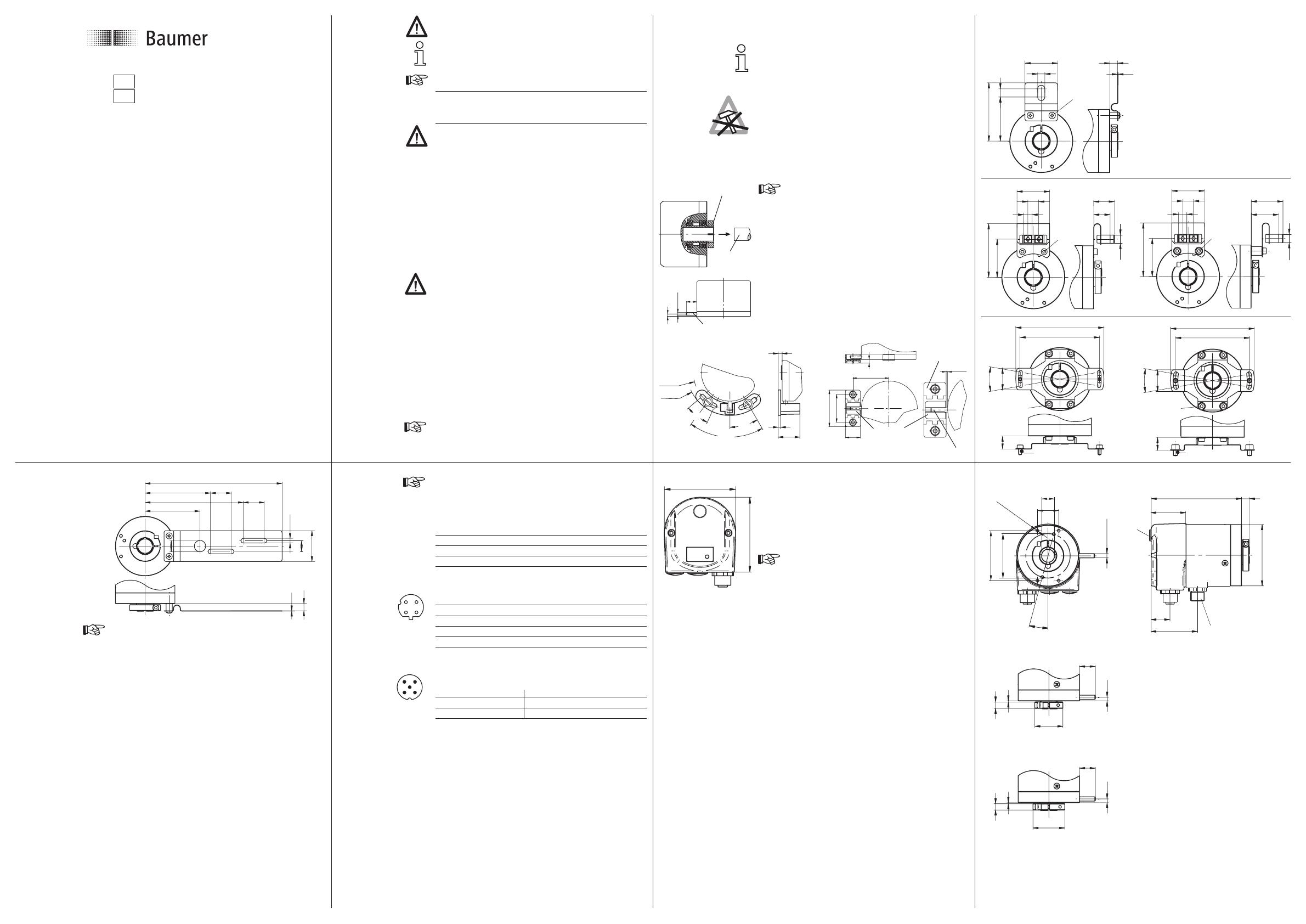
Montage
Vor Montage des Gebers, Klemmring vollständig öffnen. -
Schläge oder Schocks auf Gehäuse und Welle vermeiden. -
Gehäuse nicht verspannen. -
Drehgeber nicht öffnen oder mechanisch verändern. -
Federarme der Kupplungsfeder müssen frei beweglich sein. -
Rundlauftoleranz: Max. 0,1 mm gemessen am äus- -
sersten Punkt der Antriebswelle (Motorwelle).
Hohlwelle, Kugellager, Glasscheibe oder elektro-
nische Teile können beschädigt werden. Die si-
chere Funktion ist dann nicht mehr gewährleistet.
Hohlwellen-Befestigung
Klemmringbefestigung
Drehgeber auf die Antriebswelle (ISO-Passung f7)
vollständig aufstecken und den Klemmring fest anziehen
(max. 1,2 Nm). Eintauchtiefe 35 mm.
Mechanischer Anbau
Drehgeber über die Antriebswelle schieben und Drehmo-
mentstift in das kundenseitige Justierteil einführen
oder in das kundenseitig montierte Justierteil (mit Gum-
mifederelement) einführen.
Kupplungsfeder
Kupplungsfeder mit den Schrauben an den Befestigungslöchern des Gehäuses
montieren. Drehgeber über die Antriebswelle schieben und Kupplungsfeder an der
Anlagefläche befestigen.
(9.5)
15
3.5
ø4 fg6
Drehmomentstift
40.5
20.5
50
38
5
±0.5
1.25
Justierteil
Antriebs-
welle
Klemmring
7
0.3
6.6
30
40.5
7.5
53.5
M3
(1.2 Nm)
35
30
10
15.1
19.1
49.3
7.6
7.6
M3 (1.2 Nm)
SW2.5
35
30
10
25.1
29.1
49.3
7.6
7.6
M3 (1.2 Nm)
SW2.5
M3 (1.2 Nm)
SW2.5
20°
20
73
81
M3x6 (1.2 Nm)
12 ±0.5
20
77
68
20°
M3 (1.2 Nm)
SW2.5
12
M4x6 (1.9 Nm)
Justierteil mit
Drehmomentstift 9.5 mm
4
2.5
22
30°
67°
25°
R37.25
R43.5
Gummifeder-
element
Drehmomentstift
Abmessungen
4
3
1
2
M12-Stecker
(Buchse), D-codiert
Ausführung mit
zusätzlichem
Inkremental-
Stecker


