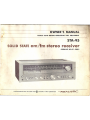
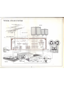
Realistic STA-95 is a versatile AM/FM stereo receiver with 46 watts per channel and a wide range of features for enjoying music and broadcasts. It has a built-in wideband AM/FM tuner with PLL-IC for stable stereo separation, and a phono preamp with linear IC for low distortion. The front-panel jacks allow easy connection of headphones, tape decks, and other audio sources. The STA-95 also features a loudness switch for enhancing sound at low volumes, and a tape dubbing switch for convenient recording.
Realistic STA-95 is a versatile AM/FM stereo receiver with 46 watts per channel and a wide range of features for enjoying music and broadcasts. It has a built-in wideband AM/FM tuner with PLL-IC for stable stereo separation, and a phono preamp with linear IC for low distortion. The front-panel jacks allow easy connection of headphones, tape decks, and other audio sources. The STA-95 also features a loudness switch for enhancing sound at low volumes, and a tape dubbing switch for convenient recording.


-
 1
1
-
 2
2
-
 3
3
-
 4
4
-
 5
5
-
 6
6
-
 7
7
-
 8
8
-
 9
9
-
 10
10
-
 11
11
-
 12
12
-
 13
13
-
 14
14
-
 15
15
-
 16
16


Realistic STA-95 is a versatile AM/FM stereo receiver with 46 watts per channel and a wide range of features for enjoying music and broadcasts. It has a built-in wideband AM/FM tuner with PLL-IC for stable stereo separation, and a phono preamp with linear IC for low distortion. The front-panel jacks allow easy connection of headphones, tape decks, and other audio sources. The STA-95 also features a loudness switch for enhancing sound at low volumes, and a tape dubbing switch for convenient recording.
Ask a question and I''ll find the answer in the document
Finding information in a document is now easier with AI
Related papers
-
Realistic LAB-2100 Owner's manual
-
-
-
-
-
-
-
-
-
Other documents
-
Yamaha CR-220 Owner's manual
-
Kawai KM-15 User manual
-
NAD 7125 Instructions For Installation And Operation Manual
-
Sansui AU-111 Operating Instructions And Service Manual
-
Rotel RC-870 User manual
-
Marantz Model 2252-B Owner's manual
-
Kenwood KR-V999D User manual
-
TEAC AD-G9320 Owner's manual
-
ONKYO TX-SV515PRO II User manual
-
Optimus Stereo Receiver STAV-3370 User manual