
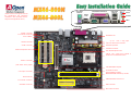
AUX-IN Connector
CD-IN Connecto
r
Front Audio Connecto
r
IrDA Connector
Front Panel Connecto
r
FDD Connecto
r
USB2.0 Connector
JP14 CMOS Clear Jumper
Resetable Fuse
478-pin CPU socket that supports Intel
®
Pentium
®
4 CPU Northwood CPU
AGP 8X/4X Expansion Slot
32-bit PCI Expansion Slot x3
184-pin DIMMx2 supports
DDR400/333/266 maximum up to 2GB
SIS 661FX/963L Chipsets
Low ESR Ca
p
acitors
ATX Power Connector
ATA100/133 IDE Connector x2
4-pin 12V. ATX Power Connector
S/PDIF Connecto
r
PS/2 Mouse
Connecto
r
SPP/EPP/ECP Parallel Port
USB2.0 Ports
RJ45 10/100
LAN Jack
PS/2 Keyboard
Connecto
r
USB2.0
Ports
COM 1 Port
V
G
A
Port
AC’97 CODEC
SYSFAN2 Connecto
r
SYSFAN1 Connecto
r
CPUFAN Connector
Case Open Connector
Line-In
Speaker Out
MIC-In
(AOpen reserves the right to revise all
the specifications and information
contained in this document which is
subject to change without notice.)
JP28
K
ey
b
oar
d/M
ouse
W
a
k
eup
J
umpe
r

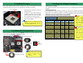
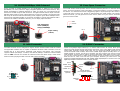
This motherboard comes with a 20-pin and 4-pin ATX power connector as shown below. Make sure you plug
in the right direction. We strongly recommend you to insert the 4-pin connector before connecting the 20-pin
connector.
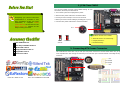
1. JP14 Clear CMOS
Everything you need to boot this
motherboard is included in this
Easy Installation Guide. For more
information, a complete Online
User's Manual can be found in the
Bonus Pack CD. Thanks for the
help of saving our earth.
PART NO: 49.89U17.001 DOC. NO: MX46800N-EG-E0310B
You can clear CMOS to restore system default setting. To clear
the CMOS, follow the procedure below.
1. Turn off the system and unplug the AC power.
2. Remove ATX power cable from connector PWR2.
3. Locate JP14 and short pins 2-3 for a few seconds.
4. Return JP14 to its normal setting by shorting pin 1 & pin 2.
5. Connect ATX power cable back to connector PWR2.
Tip: When should I Clear CMOS?
1. Boot fail because of overclocking…
2. Forget password…
3. Troubleshooting…
This Motherboard x1
This Easy Installation Guide x1
80-wire IDE Cable x1
Floppy Disk Drive Cable x1
Registration Card x1
Bonus Pack CD x1
Pin 1
2. Connecting ATX Power Connector
1
Normal
(
default
)
1
Clear CMOS

1. Pull up the CPU socket lever and up to
90-degree angle.
2. Locate Pin 1 in the socket and look for
a (golden) cut edge on the CPU upper
interface. Match Pin 1 and cut edge.
Then insert the CPU into the socket.
3. Press down the CPU socket lever and
finish CPU installation.
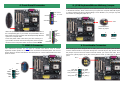
Plug in the CPU fan cable to the 3-pin CPUFAN connector. If you have chassis fan, you
can also plug it in SYSFAN1 or SYSFAN2 connector.
CPU Ratio 8x, 10x… 22x, 23x, 24x, 25x
CPU FSB (By manual) 100MHz, 133MHz, 200MHz
Northwood
CPU
CPU Core
Frequency
FSB
Clock
System
Bus
Ratio
Pentium 4 1.8G 1800MHz 100MHz 400MHz 18x
Pentium 4 2.0G 2000MHz 100MHz 400MHz 20x
Pentium 4 2.2G 2200MHz 100MHz 400MHz 22x
Pentium 4 2.2G 2200MHz 133MHz 533MHz 16x
Pentium 4 2.26G 2260MHz 133MHz 533MHz 17x
Pentium 4 2.4G 2400MHz 100MHz 400MHz 24x
Pentium 4 2.4G 2400MHz 133MHz 533MHz 18x
Pentium 4 2.53G 2530MHz 133MHz 533MHz 19x
Pentium 4 2.6G 2600MHz 200MHz 800MHz 13x
Pentium 4 2.66G 2660MHz 133MHz 533MHz 20x
Pentium 4 2.8G 2800MHz 133MHz 533MHz 21x
Pentium 4 2.8G 2800MHz 200MHz 800MHz 14x
Pentium 4 3.06G 3066MHz 133MHz 533MHz 23x
Pentium 4 3.20G 3200MHz 200MHz 800MHz 16x
5. Setting CPU Voltage & Frequency
Setting CPU Core Voltage
This motherboard supports CPU VID function. The CPU core voltage will be automatically
detected.
Setting CPU Frequency
This motherboard is CPU jumper-less design, you can set CPU frequency through the
BIOS setup, and no jumpers or switches are needed. The default setting is "1MHz Stepping
Adjustment". You can adjust the FSB from "CPU Host/SDRAM/PCI Clock" for overclocking.
BIOS Setup > Frequency / Voltage Control > CPU Speed Setup
3. Installing Processor
Note: If you do not match the CPU
socket Pin 1 and CPU cut edge well,
you may damage the CPU.
CPU socket lever
Note: Some CPU fans do
not have sensor pin so they
cannot support fan
monitoring.
CPUFAN Connector
Warning: SIS
661FX Chipset
supports maximum
400MHz system
bus and 66MHz
AGP clock; higher
clock setting may
cause serious
system damage.
4. Installing CPU & System Fan
SYSFAN2 Connector
This socket supports Micro-FC-PGA2 package CPU, which is the latest CPU package
developed by Intel. Other forms of CPU package are impossible to be fitted in.
SYSFAN1 Connector
GND
+12V
SENSOR
Note: Since the
latest processor,
Northwood, would
detect the clock
ratio automatically,
you may not be
able to adjust the
clock ratio in BIOS
manuall
y
.

8. JP28 Keyboard/Mouse Wakeup Jumper
9. Front Audio Connector
7. USB2.0 Connector
Attach the power LED, speaker, and reset switch connectors to
the corresponding pins. If you enable “Suspend Mode” item in
BIOS Setup, the ACPI & Power LED will keep flashing while the
system is in suspend mode.
Locate the power switch cable from your ATX housing. It is
2-pin female connector from the housing front panel. Plug this
connector to the soft-power switch connector marked SPWR.
This motherboard provides keyboard / mouse wakeup function. You can use JP28 to enable
or disable this function, which could resume your system from suspend mode with keyboard
or mouse installed. The factory default setting is set to “Disable” (1-2), and you may enable
this function by setting the jumper to 2-3.
6. Front Panel Connector
If the housing has been designed with an audio port on the front panel, you’ll be able to
connect onboard audio to front panel through this connector. By the way, please remove
the jumper cap from the Front Audio Connector before you connect the cable. Do not
remove this yellow jumper cap if your housing doesn’t have an audio port on the front
panel.
Pin 1
This motherboard provides six USB ports to connect USB devices such as mouse,
keyboard, modem, printer, etc. There are four connectors on the back panel. You can use
proper cables to connect USB devices from back panel or connect USB header to the front
p
anel of chassis.
Pin1
+5V
SBD3-
SBD3+
GND
NC
+5V
SBD2-
SBD2+
GND
KEY
1
1
SPEAKER
IDE LED
Power Switch
ACPI & Power
LED
RESET
1
SPWR
GND
ACPILED-
GND
ACPILED+
NC
NC
GND
RESET
GND
NC
NC
+5V
IDE LED
IDE LED
+5V
+5V
GND
NC
SPEAKER
JP28 KB/Mouse
Wake-up Jumper
Pin1
1
Disable
(Default)
1
Enable
1
AUD_GND
AUD_VCC
AUD_RET_R
KEY
AUD_RET_L
AUD_MIC
AUD_MIC_BIAS
AUD_FPOUT_R
NC
AUD_FPOUT_L

S/PDIF (Sony/Philips Digital Interface) is a newest audio transfer file format, which provides
impressive audio quality through optical fiber and allows you to enjoy digital audio instead of
analog audio. Through a specific audio cable, you can connect the S/PDIF connector to other
end of the S/PDIF audio module, which bears S/PDIF digital output. Normally there are two
S/PDIF outputs as shown, one for RCA connector, the most common one used for consumer
audio products, and the other for optical connector with better audio quality. Same as outputs,
you can also connect RCA or optical audio products to input connectors on the module and
have the voice or music come out from your computer. However, you must have a S/PDIF
supported speaker/amplifier/decoder with S/PDIF digital input/output to connect to the S/PDIF
digital input/output to make the most out of this function..
12. Case Open Connector
10. 10/100/1000Mbps LAN Onboard
On the strength of Realtek 8201BL Phy (for MX46-800N) or 8110S-32 LAN controller
(MX46-800L) on board, which are highly integrated platform LAN connect devices, they
provide 10/100Mbps or gigabits Ethernet for office and home use. The Ethernet RJ45
connector is located on top of USB connectors. The right-hand side LED on RJ45 connector
indicates linking mode; It shows yellow whenever accessing to network. The left-hand side
LED on RJ45 connector indicates transferring mode; it lights in green when 100Mbps LAN is
connected (no light while 10Mbps is connected), and lights in orange when gigabits LAN is
connected. To enable or disable this function, you can simply adjust it in BIOS.
The “CASE OPEN” header provides chassis intrusion-monitoring function. To make this function
works, you have to enable it in the system BIOS, connect this header to a sensor somewhere on
the chassis. So, whenever the sensor is triggered by lights or by the opening of the chassis, the
system will beep to inform you. Please be informed that this useful function only applies to
advanced chassis, you may purchase an extra sensor, attach it on your chassis, and make a
good use of this function.
The IrDA connector can be configured to support wireless infrared module. With this module
and application software such as Laplink or Windows 95 Direct Cable Connection, user can
transfer files to or from laptops, notebooks, PDA devices and printers. This connector
supports HPSIR (115.2Kbps, 2 meters) and ASK-IR (56Kbps). Install the infrared module
onto the IrDA connector and enable the infrared function from BIOS Setup, UART Mode.
Make sure that you plug the IrDA connector with correct orientation.
13. S/PDIF Connector
11. IrDA Connector
Pin 1
1
GND
Senso
r
Right: Linking
(Yellow)
Left: Transferring
Green (100Mbps)
Orange (1000Mbps)
Pin 1
1
KEY
GND
IR_RX
NC
+5V
IR_TX
IrDA Connector
Pin 1
5
1
SPDIFOUT
NC
+5V
GND
SPDIFIN
S/PDIF Module
(User Upgrade Optional)
S/PDIF
Cable
S/PDIF IN
(RCA)
(Optical)
S/PDIF OUT
S/PDIF OUT
S/PDIF IN

After you finish jumper settings and connect correct cables, power on and
enter the BIOS Setup. Press <Del> during POST (Power On Self Test).
Choose "Load Setup Defaults" for recommended optimal performance.
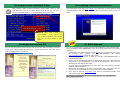
14. Power-on and Load BIOS Setup
15. AOpen Bonus Pack CD
17. BIOS Upgrade
You may accomplish BIOS upgrade procedure with EzWinFlash by the following steps,
and it’s STRONGLY RECOMMENDED to close all the applications before you start the
upgrading.
1. Download the new version of BIOS package zip file from our official web site. Unzip
the download BIOS package (ex: WMX46800N102.ZIP) with WinZip
(http://www.winzip.com) in Windows environment.
2. Save the unzipped files into a folder, for example, WMX46800N102.EXE &
WMX46800N102.BIN.
3. Double click on WMX46800N102.EXE, EzWinFlash will detect the model name and
BIOS version of your motherboard. If you had got the wrong BIOS, you will not be
allowed to proceed with the flash steps.
4. You may select preferred language in the main menu, then click [Start Flash] to start
the BIOS upgrade procedure.
5. EzWinFlash will complete all the process automatically, and a dialogue box will pop
up to ask you to restart Windows. You may click [YES] to reboot Windows.
6. Press <Del> at POST to enter BIOS setup, choose "Load Setup Defaults", then
“Save & Exit Setup”. Done!
It is strongly recommended NOT to turn off the power or run any application
during FLASH PROCESS.
16. Installing Onboard Sound Driver
You can use the autorun menu of Bonus CD. Choose the utility and driver and select
model name. After selecting the model name, you can install its AGP, VGA, IDE, Audio,
LAN and USB2.0 drivers from this CD.
Del
Warning: Please avoid of using "Load
Turbo Defaults", unless you are sure
your system components (CPU, DRAM,
HDD, etc.) are good enough for turbo
setting.
This motherboard comes with AC97 CODEC. This audio driver supports Windows 98SE
and upper Windows OS; you can find the audio driver from the Bonus Pack CD auto-run
menu.

MX46-800N R1.02 July 01. 2003 AOpen Inc.
Award Plug and Play BIOS Extension v1.0A
Copyright © 2003, Award Software, Inc.
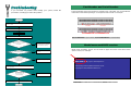
If you encounter any trouble while booting your system, follow the
procedures accordingly to resolve the problem.
Part Number and Serial Number
The Part Number and Serial number are printed on bar code label. You can find the bar
code label on the outside packing or on component side of PCB. For example:
Model name and BIOS version
Model name and BIOS version can be found on upper left corner of first boot screen
(POST screen). For example:
MX46-800N is model name of motherboard; R1.02 is BIOS version
Make sure if the jumper settings for CPU and DRAMs are correct.
Clear CMOS.
Install the VGA card. Then connect your monitor and keyboard.
The problem was probably caused
by power supply or motherboard
failure. Please contact your reselle
r
or local distributor for repairing.
Perhaps your VGA card or monito
r
is defective.
No
Yes
No
Yes
It is very possible that your keyboard
is defective.
During system rebooting, press Del to enter BIOS Setup. Choose
“Load Setup Default".
The problem should be caused by the
IDE cables or HDD itself.
Re-install Windows 95, Windows 98 or Windows NT.
Yes
Yes
Turn off the power and unplug the AC power cable, then remove all
of the addon cards and cables, including VGA, IDE, FDD, COM1,
COM2 and Printer.
Turn on the power, and check if
the power supply and CPU fan
work properly.
Start
Check if there is display.
Press Ctrl, and Alt key at the
same time, hold them and then
press Del to see if the
s
y
stem reboots.
Turn off the system and
re-connect the IDE cable.
Check if the system can
reboot successfully.
End
No
No
P/N: 91.88110.201 is part number, S/N: 91949378KN73 is serial number.
Part No. Serial No.
Part No.
Serial No.

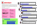
Dear Customer,
Thanks for choosing AOpen products. To provide the best and fastest service to
our customer is our first priority. However, we receive numerous emails and
phone-calls worldwide everyday, it is very hard for us to serve everyone on time.
We recommend you follow the procedures below and seek help before contact
us. With your help, we can then continue to provide the best quality service to
more customers.
Thanks very much for your understanding!
AOpen Technical Supporting Team
Web Site: http://english.aopen.com.tw/
E-mail: Send us email by going through the contact form below.
English http://english.aopen.com.tw/tech/default.htm
Japanese http://www.aopen.co.jp/tech/default.htm
Chinese http://www.aopen.com.tw/tech/default.htm
German http://www.aopencom.de/tech/default.htm
Simplified Chinese http://www.aopen.com.cn/tech/default.htm
Pacific Rim
AOpen Inc.
Tel: 886-2-3789-5888
Fax: 886-2-3789-5899
Europe
AOpen Computer b.v.
Tel: 31-73-645-9516
Email: [email protected]L
Germany
AOpen Computer GmbH.
Tel: 49-2131-1243-710
Fax: 49-2131-1243-999
China
艾爾鵬國際貿易(上海)有限公司
Tel: 86-21-6225-8622
Fax: 86-21-6225-7926
Japan
AOpen Japan Inc.
Tel: 81-048-290-1800
Fax: 81-048-290-1820
America
AOpen America Inc.
Tel: 1-510-489-8928
Fax: 1-510-489-1998
Online Manual: To download manual, please log on and then select your
preferred language. Under “Type” directory, choose “Manuals” to go to our
manual database. You can also find the manual and EIG in AOpen Bonus Pack.
http://download.aopen.com.tw/downloads
1
1
Test Report: We recommend you to choose board/card/device from the
compatibility test reports for assembling your PC. It may prevent incompatibility
problems.
http://english.aopen.com.tw/tech/report/default.htm
2
2
FAQ: Here we list problems that users often encounter and FAQ
(Frequently Asked Questions). You may select your preferred language
after log on and find a solution to your problem.
http://club.aopen.com.tw/faq/
5
5
Download Software: After log on and having language selected, you may
get the latest updated BIOS/utility and drivers you need under “Type”
directory. In most case, newer versions of drivers and BIOS have solved
earlier bugs or compatibility problems.
http://download.aopen.com.tw/downloads
3
3
eForum: AOpen eForum is provided to discuss our products with other users, in
which your problem probably had been discussed before or will be answered.
After log on, you may select your preferred language under “Multi-language”.
http://club.aopen.com.tw/forum/
4
4
Contact Distributors/Resellers: We sell our products through resellers
and integrators. They should know your system configuration very well
and should be able to solve your problem efficiently and provide important
reference for you.
6
6
Contact Us: Please prepare detail system configuration and error
symptom before contacting us. The part number, serial number
and BIOS version are also very helpful.
7
7
-
 1
1
-
 2
2
-
 3
3
-
 4
4
-
 5
5
-
 6
6
-
 7
7
-
 8
8


AOpen MX46-800N Easy Installation Manual
- Type
- Easy Installation Manual
- This manual is also suitable for
Ask a question and I''ll find the answer in the document
Finding information in a document is now easier with AI
Related papers
-
AOpen s651M Easy Installation Manual
-
-
-
-
-
-
-
-
-