iNslallaliONiNSIRUcliONS
READ ALL iNSTRUCTiONS BEFORE iNSTALLATiON
iNSTALLATiONSAFETY iNSTRUCTiONS(continued)
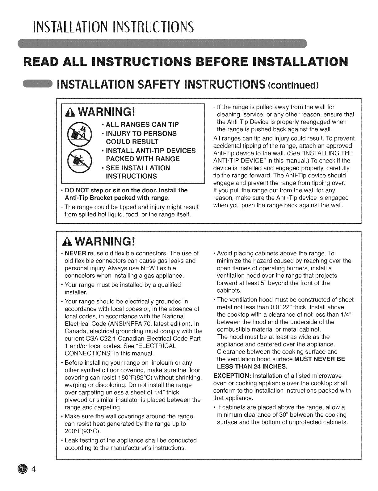
WARNING!
• ALL RANGES CAN TiP
• iNJURY TO PERSONS
COULD RESULT
• iNSTALL ANTI-TIP DEVICES
PACKED WiTH RANGE
• SEE iNSTALLATiON
iNSTRUCTiONS
• DO NOT step or sit on the door. Install the
Anti-Tip Bracket packed with range.
- The range could be tipped and injury might result
from spilled hot liquid, food, or the range itself.
- If the range is pulled away from the wall for
cleaning, service, or any other reason, ensure that
the Anti-Tip Device is properly reengaged when
the range is pushed back against the wall.
All ranges can tip and injury could result. To prevent
accidental tipping of the range, attach an approved
Anti-Tip device to the wall. (See "INSTALLING THE
ANTI-TIP DEVICE" in this manual.) To check if the
device is installed and engaged properly, carefully
tip the range forward. The Anti-Tip device should
engage and prevent the range from tipping over.
If you pull the range out from the wall for any
reason, make sure the Anti-Tip device is engaged
when you push the range back against the wall.
& WARNING!
• NEVER reuse old flexible connectors. The use of
old flexible connectors can cause gas leaks and
personal injury. Always use NEW flexible
connectors when installing a gas appliance.
•Your range must be installed by a qualified
installer.
•Your range should be electrically grounded in
accordance with local codes or, in the absence of
local codes, in accordance with the National
Electrical Code (ANSI/NFPA 70, latest edition). In
Canada, electrical grounding must comply with the
current CSA C22.1 Canadian Electrical Code Part
1 and/or local codes. See "ELECTRICAL
CONNECTIONS" in this manual.
• Before installing your range on linoleum or any
other synthetic floor covering, make sure the floor
covering can resist 180°F(82°C) without shrinking,
warping or discoloring. Do not install the range
over carpeting unless a sheet of 1/4" thick
plywood or similar insulator is placed between the
range and carpeting.
• Make sure the wall coverings around the range
can resist heat generated by the range up to
200°F(93°0).
• Leak testing of the appliance shall be conducted
according to the manufacturer's instructions.
• Avoid placing cabinets above the range. To
minimize the hazard caused by reaching over the
open flames of operating burners, install a
ventilation hood over the range that projects
forward at least 5" beyond the front of the
cabinets.
• The ventilation hood must be constructed of sheet
metal not less than 0.0122" thick. Install above
the cooktop with a clearance of not less than 1/4"
between the hood and the underside of the
combustible material or metal cabinet.
The hood must be at least as wide as the
appliance and centered over the appliance.
Clearance between the cooking surface and
the ventilation hood surface MUST NEVER BE
LESS THAN 24 iNCHES.
EXCEPTION: installation of a listed microwave
oven or cooking appliance over the cooktop shall
conform to the installation instructions packed with
that appliance.
• if cabinets are placed above the range, allow a
minimum clearance of 30" between the cooking
surface and the bottom of unprotected cabinets.


