
1
USER’S MANUAL
GR1200
This manual contains important safety instructions. Please follow all instructions during installation. Read this manual thoroughly before unpacking,
installing or operating.
Caution: Risk of Electric Shock
• The UPS contains batteries. The output outlets may be electrically live even when the UPS is disconnected from the AC mains.
• The UPS contains potentially hazardous voltages. Do not open the units as there are no user serviceable parts. All maintenance and
servicing should be performed by qualified service personnel.
• Risk of electric shock, Battery Circuit is not isolated from AC input, hazardous voltage may exist between battery terminals and ground. Test
before servicing and use insulated tools.
NOTE: The UPS is designed to be for use with computer loads only.
Caution:Do not connect a laser printer to the UPS.
A laser printer draws significantly more power than other types of equipment and may overload the UPS.
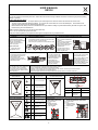
SETUP
1 Inspection
Inspect the UPS upon receipt.
Notify the carrier and dealer if there
is damage. The package is
recyclable; save it for reuse or
dispose of it properly.
Inspect accessories:
① Power cable 1PCS
USER MANUAL 1PCS
2 Choose an installation location
- Avoid locations that are excessively humid, near water,
near heat sources or in direct sunlight
- Allow 1inch (2.5cm) clearance on each side of the UPS
3 Connecting Equipment and Power to the UPS
4 Connect Modem/ Phone / Network for Surge Protection (Optional)
5 Connect Interface Device
6 Turn ON/OFF the UPS
Turn on the UPS: Press the UPS
On/OFF Switchfor approx. 3
seconds, then the Buzzer sounds
twice, the UPS will start-up.
Turn off the UPS: Press the UPS
On/OFF Switch for approx. 3
seconds, then the Buzzer sounds
twice, the UPS will shutdown.
7 Cold Start Function
When the UPS is OFF and no utility input
power is present, use the “Cold Start”
feature to apply power to the loads from
UPS‘s battery. Press the “ON/OFF” switch
until the UPS beeps.
8 Software Download and Installation
Please follow steps below to download and install monitoring software:
1. Go to the website http://www.ablerex.com.sg/downloads.html
2. Depending on the computer OS, select Emily software (for Win 7&8 OS, select Emily2) and click download.
3. Follow the on-screen instructions to install the software.
4. When the computer restarts, the monitoring software automatically search and connects to the UPS.
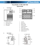
FRONT PANEL EXPLANATIONS
GR600/GR800–LEDFRONT
PANEL(STANDARD)
Symbol
LED
Color
Description/function
GR600/GR800/R1200/GR1800/GR2000
– LCD FRONT PANEL(OPTION)
N/A
Turn-on/Turn-off Switch
Green
Lit: Line mode
Dim: Abnormal input
voltage and frequency
1.Line mode
4. Battery capacity
7.Fault
Yellow
Lit: Battery mode
Flashing: Battery Low
2.Battery mode
5. Load level
8.Tack switch for
Turn-on/Turn-off
3.AVR mode
6.Measurement
Target & Value
Red
Lit: System malfunction
or abnormal
GR1200/GR1800/GR2000 – LED
FRONT PANEL(STANDARD)
Symbol
LED
Color
Description/function
REAR PANEL EXPLANATIONS
N/A
Turn-on/Turn-off Switch
GR600/GR800 REAR PANEL
1. AC Input Outlet
2. Fuse
3. Output Connector:
4x Thailand Outlets
4. USB (Standard)
GR1200/GR1800/GR2000 REAR PANEL
1. AC Input Outlet
2. Fuse
3. Output Connector:
6x Thailand Outlets
4. USB (Standard)
5. Fan
Green
Lit: Line mode
Flashing: Battery mode
Red
Lit: System malfunction or
abnormal
N/A
Load
N/A
Battery
Green
Load Percentage/
Battery Capacity
Step1: Connect the UPS to the
AC mains.
Step2: Connect the equipment
to the UPS output outlets.
Step3: Switch on the AC Mains,
follow by the UPS then the
equipment last.
*Plug the UPS into the AC
Mains to charge for 8 hours
before using the UPS.
- For modem/phone line protection,
connect equipment to the RJ11
port using RJ11 cable.
- For surge protection, connect
equipment to the RJ45 port using
Ethernet/RJ45 cable.
The UPS is equipped with
two interface ports: a USB
port (Standard) and a 9-pin
RS232 port (Optional)
allowing advanced
communication network
between the UPS and a
computer (network).
1
2
3
5
4
1
2
3
4

2
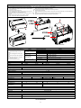
REPLACING THE BATTERY
Note:Once the battery is disconnected, the loads are not protected
from power outages.
1. Use an insulated philip screwdriver to remove the four screws located
at the base of the UPS.
2. Remove the front panel and top cover.
3. Use an insulated philip screwdriver to remove the two screws from the
battery holding plate. (for 1500L/1800L/2200L only)
4. Disconnect the battery cable terminals before removing the battery from
the UPS.
Step1: Loosen the black cable from the negative (-) terminal.
Step2: Loosen the red cable from thepositive (+) terminal.
5. Connect the battery cables to the terminals of thenew battery.
Step1: Insert the black cable to the negative (-) terminal.
Step2: Insert the red cable to thepositive (+) terminal.
Note: Small sparks at the battery connectors are normal during connection.
6. Slide the battery into the UPS.
7. Use an insulated philip screwdriver to fasten the two screws on the battery holding plate. (for 1500L/1800L/2200L
only)
8. Close the front panel and fasten the four screws located at the base of the UPS.
9. Dispose off the old battery properly at an appropriate recycling facility.
TROUBLESHOOTING
Refer to the steps below should the UPS fail to
function correctly
Step 1: Is the AC Mains switch in the “ON”
position?
Step 2:Is the UPS plugged into the AC power
supply?
Step 3: Is the power supply within specified unit
values?
Step 4: Has the fuse gone in the mains plug?
Step 5: Is the UPS overload?
Step 6: Is the battery flat or defective?
Situation
Problem / Possible Causes
Solution
No LEDs display on the front panel.
Battery voltage is low.
Charge the UPS at least 6 hours.
Battery is defective.
Replace the battery with the same capacity.
The UPS is not turned on.
Press the power switch again to turn on the UPS.
Alarm beeps continuously when
the Utility is normal.
The UPS is overloaded.
Remove some loads/equipment first. The connected equipment exceeds the
UPS specified ‘capacity/load”.
UPS does not provide
expected backup time.
The UPS is overloaded.
Remove some loads/equipment first. The connected equipment exceeds the
UPS specified ‘capacity/load”.
Battery voltage is too low.
Charge the UPS at least6 hours.
Battery is defective.
Replace the battery with the same capacity.
The Utility is normal but LED
is flashing.
Power cord is loose.
Reconnect the power cord properly.
Description
Ablerex GR600/GR800 SPECIFICATIONS
Ablerex GR1200/GR1800/GR2000 SPECIFICATIONS
Model
GR600
GR800
GR1200
GR1800
GR2000
Input
Voltage
220/230/240VAC
Voltage Range
160~290Vac
Output
Voltage Regulation
+/- 10%
Transfer Time
Typical 2-6ms, 10 ms max.
Waveform
Simulated Sine Wave
Battery
Type & Number
12V/7Ah x 1
12V/9Ah x 1
12V/7Ah x 2
12V/7Ah x 2
12V/9Ah x 2
Charging time
4-6 hours recover to 90% capacity
Physical
Dimension (WxHxD, mm)
100 x 140 x 292
148 x 198 x 315
Net Weight (kg)
5
5.5
8
11
12
Packaging Dimension
(WxHxD,mm)
137 x 226 x 321
229 x 302 x 411
Gross Weight (kg)
5.5
6
9
12
13
Environment
Humidity
0-90 % RH @ 0-40 C (non-condensing)
Noise level
Less than 40 dB
Certification
Safety Standard
EN62040-2
EMC/Surge Standard
EN61000-3-2, EN61000-3-3
Mark
CE, RoHS, TISI
GR600/GR800
GR1200/GR1800/GR2000
STEP1
STEP2
STEP1
STEP2
192321982006000
-
 1
1
-
 2
2


Ablerex GR1200 User manual
- Type
- User manual
Ask a question and I''ll find the answer in the document
Finding information in a document is now easier with AI
Related papers


Other documents
-
Hitachi GR2000-B Series User manual
-
 Sollatek Voltsure Ultima LCD 1500 User manual
-
 Powercom 425A User manual
-
-
 PowerWalker VI 750 T-HID IEC UK Owner's manual
-
-
 OPTI-UPS VS375C User manual
-
ABB SM3000 User manual
-
-


