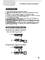
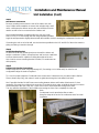
Quietside QSHE-092 is a ductless mini split system designed to provide heating and cooling for residential and commercial spaces. With a rated capacity of 9,000 BTU/h, it is suitable for rooms up to 400 square feet. The system consists of an indoor unit and an outdoor unit that are connected by refrigerant lines. The indoor unit features a sleek design with a wireless remote control for easy operation. It offers various operating modes, including auto, cool, dry, fan, and heat, allowing you to customize the temperature and humidity levels in your space.
Quietside QSHE-092 is a ductless mini split system designed to provide heating and cooling for residential and commercial spaces. With a rated capacity of 9,000 BTU/h, it is suitable for rooms up to 400 square feet. The system consists of an indoor unit and an outdoor unit that are connected by refrigerant lines. The indoor unit features a sleek design with a wireless remote control for easy operation. It offers various operating modes, including auto, cool, dry, fan, and heat, allowing you to customize the temperature and humidity levels in your space.


-
 1
1
-
 2
2
-
 3
3
-
 4
4
-
 5
5
-
 6
6
-
 7
7
-
 8
8
-
 9
9
-
 10
10
-
 11
11
-
 12
12
-
 13
13
-
 14
14
-
 15
15
-
 16
16
-
 17
17
-
 18
18
-
 19
19
-
 20
20
-
 21
21
-
 22
22
-
 23
23
-
 24
24
-
 25
25
-
 26
26


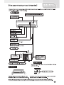
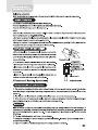
Quietside QSHE-092 Installation guide
- Category
- Heat pumps
- Type
- Installation guide
Quietside QSHE-092 is a ductless mini split system designed to provide heating and cooling for residential and commercial spaces. With a rated capacity of 9,000 BTU/h, it is suitable for rooms up to 400 square feet. The system consists of an indoor unit and an outdoor unit that are connected by refrigerant lines. The indoor unit features a sleek design with a wireless remote control for easy operation. It offers various operating modes, including auto, cool, dry, fan, and heat, allowing you to customize the temperature and humidity levels in your space.
Ask a question and I''ll find the answer in the document
Finding information in a document is now easier with AI
Other documents
-
 Sea Breeze 24A43ZCX Owner's manual
-
 Sea Breeze 9H43YCX Installation guide
-
 Thermalzone MSC412HP13115A Owner's manual
-
 Thermal Zone HEAT PUMP 12H45ZOIMI Installation and Maintenance Manual
-
 Thermal Zone 12H47YIMI Installation and Maintenance Manual
-
 Enviroair KWH12000 Owner's manual
-
EMI 13 SEER EnviroAir Installation & Operation Manual
-
Mitsubishi Electric SG-1-SD Installation guide
-
 Thermalzone MS29A13115A Installation guide
-
 Sea Breeze 9A23YGX Owner's manual


