Page is loading ...

310-0510/-0610/-0710
Integrated Hydrostatic Transaxle
Service and Repair Manual
BLN-51260
July, 2011

Table of Contents
Section Page
Foreword........................................................................................................................................ 1
Section 1 Description and Operation.......................................................................................... 2
Introduction........................................................................................................................................................ 2
General Description............................................................................................................................................ 2
Hydraulic Schematic........................................................................................................................................... 3
External Features 310-0510............................................................................................................................... 4
Model Recognition ............................................................................................................................................. 5
Technical Specifications..................................................................................................................................... 6
Product Identification.......................................................................................................................................... 6
Section 2 Safety ............................................................................................................................ 7
Personal Safety.................................................................................................................................................. 7
Tool Safety......................................................................................................................................................... 7
Work Area Safety............................................................................................................................................... 7
Servicing Safety................................................................................................................................................. 7
Section 3 Troubleshooting........................................................................................................... 8
Section 4 Service and Maintenance ............................................................................................ 9
External Maintenance......................................................................................................................................... 9
Service and Maintenance Procedures................................................................................................................ 9
Fluids................................................................................................................................................................. 9
Fluid Change.................................................................................................................................................... 10
Purging Procedures.......................................................................................................................................... 11
Return to Neutral Setting.................................................................................................................................. 12
Brake Maintenance.......................................................................................................................................... 13
Friction Pack Adjustment.................................................................................................................................. 13
Section 5 Repair.......................................................................................................................... 14
How To Use This Section................................................................................................................................. 14
General Instructions......................................................................................................................................... 14
Transaxle Removal.......................................................................................................................................... 14
Limited Disassembly ........................................................................................................................................ 14
Tools and Torques........................................................................................................................................... 15
Brake Assembly and Bypass Arm..................................................................................................................... 16
Control Arm and Friction Pack.......................................................................................................................... 17
Seal Kit Replacement ...................................................................................................................................... 18
Side Housing.................................................................................................................................................... 19
Axle Shaft, Differential and Reduction Gears.................................................................................................... 20
Motor Shaft and Bypass Rod............................................................................................................................ 21
Input Shaft ....................................................................................................................................................... 22
Hydraulic Components................................................................................................................................ 23-26
Transaxle Installation ....................................................................................................................................... 27
Assembly After a Complete Teardown.............................................................................................................. 27
Sealant Application..................................................................................................................... 28
310-0610 & 310-0710 IHT ............................................................................................................ 29
Description....................................................................................................................................................... 29
Features........................................................................................................................................................... 29
Transaxle Removal.......................................................................................................................................... 29
Parts List................................................................................................................................. 30-35
Glossary of Terms.................................................................................................................. 36-37

310-0510 IHT 1
FOREWORD
Headquartered in Sullivan, Illinois, Hydro-Gear®
is a world leader in the design, manufacture,
and service of quality hydrostatic transaxles for
the lawn and garden industry. The mission of
our company is to be recognized by our cus-
tomers and the industry as a world-class suppli-
er and the quality leader in everything we do.
This Service and Repair Manual is designed to
provide information useful in servicing and
troubleshooting the Hydro-Gear 310-0510
Integrated Hydrostatic Transaxle (IHT). Trou-
bleshooting for the 310-0510 is further illustrat-
ed in video BLN-51368 (NTSC).
Also included is a glossary of terms that are
frequently used throughout the industry and in
Hydro-Gear service publications. Understand-
ing terminology is very important!
It is necessary, and good shop practice, that
your service area be equipped with the proper
tools and the mechanics be supplied with the
latest information available. All repair
procedures illustrated in this guide are
suggested, but preferred methods of repair.
Repair procedures require that the transaxle
unit be removed from the vehicle.
This is not a certification, test or study guide for
a certification test. If a technician is interested
in certification they should contact an agent
representing OPEESA (Outdoor Power Equip-
ment and Engine Service Association) at (860)
767-1770 or their Hydro-Gear Distributor. Many
distributors will be hosting certification testing.
These study guides will cover most of the prod-
ucts and manufacturers in our industry.
For more information about Hydro-Gear or our
products, please contact your Central Service
Distributor, or call our Customer Service
Department at (217) 728-2581.

310-0510 IHT
2
INTRODUCTION
The purpose of this manual is to provide
information useful in servicing the Hydro-Gear®
Integrated Hydrostatic Transaxle (IHT). This
manual includes the IHT’s general description,
hydraulic schematic, technical specifications,
servicing and troubleshooting procedures.
The transaxle normally will not require servicing
during the life of the vehicle in which it is
installed. Should other servicing be required,
the exterior of the transaxle will need to be
thoroughly cleaned before beginning most
procedures. Do not wash the transaxle while it
is hot. Do not use a pressure washer to clean
the unit.
GENERAL DESCRIPTION
The 310-0510 is a self contained unit designed
for the transfer and control of power. It provides
an infinitely variable speed range between zero
and maximum in both forward and reverse
modes of operation.
This transaxle uses a variable displacement
pump with a maximum displacement of 10cc
per revolution, and motor with a fixed displace-
ment of 10cc per revolution. The variable dis-
placement pump features a trunnion mounted
swashplate with a direct-proportional displace-
ment control. Reversing the direction of the
swashplate reverses the flow of oil from the
pump and thus reverses the direction of the
motor output rotation. The pump and motor are
of the axial piston design and utilize spherical
nosed pistons which are held against a thrust
race by internal compression springs.
The 310-0510 has a self contained fluid supply
and an internal filter. The fluid is forced through
the filter by a positive “head” on the fluid in the
housing/expansion tank with an assist by the
negative pressure created in the pump pistons
as they operate.
The check valves in the center section are used
to control the makeup flow of the fluid to the low
pressure side of the loop.
A check ball lifting bypass is utilized in the 310-
0510 to permit moving the vehicle for a short
distance at a maximum of 2 m.p.h. (3.2 Km/h)
without starting the engine.
The 310-0510 utilizes an in-line floating disc
brake controlled by a “cam” style actuating arm.
SECTION 1. DESCRIPTION AND OPERATION
WARNING
Actuating the bypass will result in the
loss of hydrostatic braking capacity.
The machine must be stationary on a
level surface and in neutral when
actuating the bypass.
Figure 1. 310-0510 Hydraulic Schematic

HYDRAULIC SCHEMATIC
Figure 2 provides an illustration of the hydraulic
oil circuit. The oil supply for the hydraulic
system of the 310-0510 IHT is also utilized for
lubricating the components of the final drive
assembly.
The input shaft and pump cylinder block are
turned in one direction only by the engine/drive
belt/pulley combination. Output of the oil flow is
controlled by the direction and amount that the
variable swashplate is angled. As the pump
pistons compress they force the oil to flow
through one of two passageways (forward or
reverse) in the center section to the motor
cylinder block and motor shaft. Since the motor
has a fixed displacement angle it is forced to
turn with the flow of oil. As the angle of the
pump swashplate is increased the amount of oil
being pumped will increase and cause a higher
speed output of the motor. Reversing the angle
of the swashplate will reverse the direction of
oil flow.
During the operation of the transaxle, fluid is
“lost” from the hydraulic loop through leak paths
designed into the product for lubrication
purposes (around pistons, under the rotating
cylinder blocks, etc.). This “lost” fluid returns to
the transaxle housing, then is pulled back into
one of the check valves depending upon the
direction of vehicle operation. All of this oil
must pass through an internal filter.
The motor cylinder block mounts onto a splined
motor shaft which drives the gear train.
The bypass feature in the 310-0510 has a
mechanical lever which lifts the check valve
balls off their seat. This allows oil flow from the
cylinder blocks to be discharged.
Figure 2. 310-0510 Hydraulic Flow Illustration
INPUT SHAFT
RESERVOIR
TRANSAXLE HOUSING
CHECK VALVE
BYPASS ACTUATOR
VARIABLE SWASH PLATE
DISPLACEMENT PUMP
10 CC VARIABLE
FILTER ASSEMBLY
CHECK VALVE
DIFFERENTIAL ASSEMBLY
FIXED DISPLACEMENT ANGLE
CYLINDER BLOCK ASSEMBLY
CYLINDER BLOCK ASSEMBLY
10 CC FIXED
DISPLACEMENT MOTOR

310-0510 IHT
4
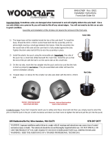
EXTERNAL FEATURES 310-0510
Return to Neutral Option
Friction Pack Option
AXLE SHAFT
FILL PORT
EXPANSION
TANK
INPUT SHAFT
CONTROL ARM
BRAKE
DISC
FAN
BRAKE ARM
BYPASS ARM
FRICTION
PACK
ADJUSTING
PUCK
BELT KEEPER
AXLE CLIP
AXLE CLIP
AXLE CLIP
AXLE CLIP

310-0510 IHT 5
MODEL RECOGNITION
618-0319 166768 104-1760
173839 036932 618-0389A

310-0510 IHT
6
TECHNICAL SPECIFICATIONS
Overall Transaxle Reduction
22.15:1
Input Speeds
Maximum: 3000 RPM
Minimum: 1800 RPM
Maximum Tire Diameter
20 inch; 508 mm
Axle Shaft Options
Type: Keyed / Double “D”
Diameter: 0.75 inch; 19.05 mm
Brake Type
Disc
Weight of Unit
30 lb; 14 kg
Technical specifications for the 310-0510 IHT are listed in Table 1.
Table 1. 310-0510 Technical Specifications
PRODUCT IDENTIFICATION
The model and configuration of the 310-0510 IHT can be determined from the label shown in
Figure 3.
Figure 3. 310-0510 Configuration Label
H Y D R O - G E A R
SULLIVAN, IL. U.S.A.
I IIIIIII IIII II II
13054 318-2400
I II IIII IIII IIIIII I II IIII
0319 Z1 401 Made in U.S.A.
Year Built
Date
(Julian - day of year )
Type of Product and Build Information
Serial Number
(unique number for that model - for that day)
Model
Number
Hydro-Gear
Ref. Number
314-0510
166768
T

310-0510 IHT 7
SECTION 2. SAFETY
This symbol points out important safety
instructions which, if not followed, could
endanger the personal safety and/or property of
yourself and others. Read and follow all
instructions in this manual before attempting
maintenance on your transaxle. When you see
this symbol - HEED ITS WARNING.
WARNING
POTENTIAL FOR SERIOUS INJURY
Inattention to proper safety, operation, or
maintenance procedures could result in per-
sonal injury, or damage to the equipment.
Before servicing or repairing the 310-0510
IHT, fully read and understand the safety
precautions described in this section.
PERSONAL SAFETY
Certain safety precautions must be observed
while servicing or repairing the 310-0510 IHT.
This section addresses some of these
precautions but must not be considered an all-
inclusive source on safety information. This
section is to be used in conjunction with all oth-
er safety material which may apply, such as:
1) Other manuals pertaining to this machine,
2) Local and shop safety rules and codes,
3) Governmental safety laws and regulations.
Be sure that you know and understand the
equipment and the hazards associated with it.
Do not place speed above safety.
Notify your supervisor whenever you feel there
is any hazard involving the equipment or the
performance of your job.
Never allow untrained or unauthorized person-
nel to service or repair the equipment.
Wear appropriate clothing. Loose or hanging
clothing or jewelry can be hazardous. Use the
appropriate safety equipment, such as eye and
hearing protection, and safety-toe and slip-
proof shoes.
Never use compressed air to clean debris from
yourself or your clothing.
TOOL SAFETY
Use the proper tools and equipment for the
task.
Inspect each tool before use and replace any
tool that may be damaged or defective.
WORK AREA SAFETY
Keep the work area neat and orderly. Be sure
it is well lit, that extra tools are put away, trash
and refuse are in the proper containers, and dirt
or debris have been removed from the working
areas of the machine.
The floor should be clean and dry, and all ex-
tension cords or similar trip hazards should be
removed.
SERVICING SAFETY
Certain procedures may require the vehicle to
be disabled in order to prevent possible injury
to the servicing technician and/or bystanders.
The loss of hydrostatic drive line power may
result in the loss of hydrostatic braking capabil-
ity. Proper brake maintenance is very important
should this condition develop.
Some cleaning solvents are flammable. Use
only approved cleaning materials. Do not use
explosive or flammable liquids to clean the
equipment.
To avoid possible fire do not use cleaning sol-
vents in an area where a source of ignition may
be present.
Discard used cleaning material in the appropri-
ate containers.

310-0510 IHT
8
UNIT OPERATING HOT
SECTION 3. TROUBLESHOOTING
WARNING
Do not attempt any servicing or adjust-
ments with the engine running.
Use extreme caution while inspecting the
drive belt assembly, and all vehicle link-
age!
Follow all safety procedures outlined in
the vehicle owner’s manual!
In many cases problems with the 310-0510 are
not related to a defective transaxle, but are
caused by slipping drive belts, partially
engaged bypass valves, and loose or
damaged control linkages. Be sure to perform
all operational checks and adjustments outlined
in Section 4, Service and Maintenance before
assuming the unit is malfunctioning. Table 2
below provides a troubleshooting check list to
help determine the cause of operational prob-
lems.
Table 2. 310-0510 Troubleshooting Checklist
Vehicle tires improperly inflated
Control linkage bent, loose or out of adjustment
Bypass partially engaged
Refer to vehicle manufacturer suggested pressure
Repair, adjust or replace vehicle linkage
Adjust bypass linkage
UNIT IS NOISY
UNIT HAS NO/LOW POWER
Oil level low or contaminated oil
Excessive loading
Brake setting incorrect
Loose parts
Bypass assembly sticking
Air trapped in hydraulic system
Debris buildup around transaxle
Brake setting incorrect
Cooling fan damaged
Oil level low or contaminated oil
Excessive loading
Air trapped in hydraulic system
Clean off debris, Page 9
Adjust brake to proper setting, Page 13
Repair or replace cooling fan
Fill to proper level or change oil, Page 10
Reduce vehicle loading, Page 9
Purge hydraulic system, Page 11
Corrective Action Possible Cause
VEHICLE DOES NOT DRIVE/TRACK STRAIGHT
Repair or replace linkage, Page 9
Repair or replace drive belt or pulley, Page 9
Control linkage bent or out of adjustment
Drive belt slipping or pulley damaged
UNIT OPERATES IN ONE DIRECTION ONLY
Fill to proper level or change oil, Page 10
Reduce vehicle loading, Page 9
Adjust brake to proper setting, Page 13
Repair or replace loose parts
Repair or replace valve or linkage
Purge hydraulic system, Page 11
Adjust to correct setting
Repair or replace linkage, Page 9
Adjust brake to proper setting, Page 13
Repair or replace drive belt or pulley, Page 9
Fill to proper level or change oil, Page 10
Reduce vehicle loading, Page 9
Repair or replace valve or linkage
Purge hydraulic system, Page 11
Engine speed low
Control linkage bent or out of adjustment
Brake setting incorrect
Drive belt slipping or pulley damaged
Oil level low or contaminated oil
Excessive loading
Bypass assembly sticking
Air trapped in hydraulic system
TRANSAXLE LEAKS OIL
Replace damaged component
Purge hydraulic system, Page 11
Damaged seals, housing, or gaskets
Air trapped in hydraulic system

310-0510 IHT 9
SECTION 4. SERVICE AND MAINTENANCE
NOTE: Any servicing dealer attempting
a warranty repair must have prior
approval before conducting maintenance
of a Hydro-Gear® product unless the
servicing dealer is a current Authorized
Hydro-Gear Service Center.
EXTERNAL MAINTENANCE
Regular external maintenance of the 310-0510
IHT should include the following:
1. Check the vehicle operator’s manual for
the recommended load ratings. Insure
the current application does not exceed
load rating.
2. Check oil level in accordance with Figure 4
Page 10.
3. Inspect the vehicle drive belt, idler pulley(s),
and idler spring(s). Insure that no belt
slippage can occur. Slippage can cause low
input speed to the transmission.
4. Inspect the transmission cooling fan for
broken or distorted blades and remove any
obstructions (grass clippings, leaves, dirt,
etc.).
5. Inspect the axle parking brake and vehicle
linkage to insure proper actuation and
adjustment of the parking brake.
6. Inspect the vehicle control linkage to the
directional control arm on transaxle. Also,
insure the control arm is securely fastened
to the trunnion arm of the transaxle.
7. Inspect the bypass mechanism on the
transaxle and vehicle linkage to insure it
actuates and releases fully.
SERVICE AND MAINTENANCE
PROCEDURES
All the service and maintenance procedures
presented on the following pages can be
performed while the 310-0510 is mounted on
the vehicle. Any repair procedures as
mentioned in the repair section of this manual
must be performed after the unit has been
removed from the vehicle.
FLUIDS
The fluids used in Hydro-Gear products have
been carefully selected, and only equivalent, or
better products should be substituted.
Typically, an engine oil with a minimum rating
of 9 cSt (55 SUS) at 230°F (110° C) and an API
classification of SL is recommended. A 20W-50
engine oil has been selected for use by the fac-
tory and is recommended for normal operating
temperatures.
FLUID VOLUME AND LEVEL
Fluid volume information is provided in Table 3.
Certain situations may require additional fluid to
be added or even replaced. Refer to Page 4
and Figure 4 for the proper fill port location.
Fill the 310-0510 to the top of the oil fill port.
Recheck the fluid level once the unit has been
operated for approximately 1 minute.
Purging may be required. Refer to the purging
procedures on page 11.

310-0510 IHT
10
FLUID CHANGE
FLUID CHANGE PROCEDURE
This transaxle is factory filled, sealed and does
not require oil maintenance. However, in the
event of oil contamination or degradation, oil
addition or change may alleviate certain perfor-
mance problems.
1.Removethetransaxlefromthevehicle.
2.Cleantheexpansiontankandoilfillport
areasofanydebris.
3.Removetheoilfillportfing.
4.Posionthetransaxlesotheoilwilldraincom-
pletelyoutofthehousing.
5.Aeralltheoilisdrainedfromthetransaxle,
removetheexpansiontankbyremovingtheself
tappingbolt(10-32x½)thatholdsthetank
supportbracket.
6.Removethetankanddraintheoilfromthe
tank.DONOTremovetheventcapfromthe
tank.DONOTremovethetankhoseor
o-ringunlessareplacementisneeded.
7.Installthetankbyfirstinserngthehoseinto
theopeningintheexpansiontank.Pushthe
tankopeningovertheo-ringtoensureaproper
seal.
8.Installthetanksupportbracketandselftapping
boltmakingsurenottocrossthreadthebolt.
Torquethebolttothelowervalueofthetorque
specificaonlistedinTable5.
9.Fillthetransaxleattheoilfillportaccordingto
Figure4.
10.Installtheoilfillportfing.
EXPANSIONTANKFUNCTION
Theexpansiontankallowsthe310‐0510to
operatefreeofairentrainmentandprovides
maximumlubricaontothemechanicaland
hydrauliccomponentsinthetransaxle.
Asthe310‐0510transaxleisoperated,oilinthe
transaxlehousingheatsupwhichcausestheoilto
expand.Theoilflowsthroughaninternalhoseto
theboomoftheventedexpansiontank.Astheoil
cools,theoilinthetransaxlehousingcontracts,
causingtheoilleveltogodowninthehousing.This
createsanegavepressureinthehousingcausing
theoiltobedrawnbackintothecase.Thiskeeps
thetransaxlehousingfullofoilatspecified
operangtemperatures.
Fluid Description Volume
20W-50 engine oil 79 fl. oz. (2336 ml.)
Table 3. Fluid Volumes for the 310-0510 IHT
Figure 4. 310-0510 Fluid Level and Fill Port
FILL PORT
OIL LEVEL
1¼" (31.75mm) Max. Depth
at 50°- 100° F (10°- 38° C)

310-0510 IHT 11
PURGING PROCEDURES
Due to the effects air has on efficiency in
hydrostatic drive applications, it is critical that it
be purged from the system.
These purge procedures should be implement-
ed any time a hydrostatic system has been
opened to facilitate maintenance or any addi-
tional oil has been added to the system.
Air creates inefficiency because its compres-
sion and expansion rate is higher than that of
the oil approved for use in hydrostatic drive
systems.
The resulting symptoms in hydrostatic systems
may be:
1. Noisy operation.
2. Lack of power or drive after short term
operation.
3. High operation temperature and excessive
expansion of oil.
Before starting, make sure the transaxle/
transmission is at the proper oil level. If it is
not, fill to the specifications outlined on page
10, Figure 4.
The following procedures should be performed
with the vehicle drive wheels off the ground,
then repeated under normal operating condi-
tions.
1. With the bypass valve open and the engine
running, slowly move the directional control
in both forward and reverse directions
(5 to 6 times), as air is purged from the unit,
the oil level will drop.
2. With the bypass valve closed and the
engine running, slowly move the directional
control in both forward and reverse
directions (5 to 6 times). Check the oil level,
and add oil as required after stopping
engine.
3. It may be necessary to repeat Steps 1 and 2
until all the air is completely purged from the
system. When the transaxle moves forward
and reverse at normal speed purging is
complete.

310-0510 IHT
12
RETURN TO NEUTRAL SETTING (FOOT CONTROL)
The return to neutral mechanism on the trans-
mission is designed to set the directional con-
trol into a neutral position when the operator
removes their foot from the foot control. Follow
the procedures below to properly adjust the
return to neutral mechanism on the transaxle:
1. Confirm the transaxle is in the operat-
ing mode (bypass disengaged). Raise the
vehicle’s drive tires off the ground to allow
free rotation.
NOTE: It may be necessary to remove
the drive tire from the axle hub to access
the linkage control and the transaxle
return arm.
2. Remove the Original Equipment Manufac-
turer’s (OEM’s) control linkage at the control
arm. Refer to Figure 5.
3. Start the engine and increase the throttle to
full engine speed.
4. Check for axle rotation. If the axles do not
rotate, go to Step 5. If the axles rotate, go to
Step 6.
5. Stop the vehicle’s engine. Reattach and ad-
just the OEM linkage according to the OEM
manual. Recheck according to Step 3 and
4. Stop the vehicle engine. Refer to Figure
5.
6. Note the axle directional movement. Stop
the vehicle engine. Loosen the adjusting
puck screw until the puck can be rotated.
Rotate the adjusting puck the opposite di-
rection of the wheel rotation in 5 degree in-
crements. Tighten the adjusting puck screw.
Refer to Table 5. Required Torque Values,
Page 15. Recheck according to steps 3 and
4. Stop the vehicle engine. Reattach and
adjust the OEM linkage according to the
OEM manual. Recheck according to steps
3 and 4. Refer to Figure 5.
WARNING
POTENTIAL FOR SERIOUS INJURY
Certain procedures require the vehicle
engine to be operated and the vehicle
to be raised off the ground. To prevent
possible injury to the servicing techni-
cian and/or bystanders, insure the
vehicle is properly secured.
WARNING
Do not attempt any adjustments with the
engine running. Use extreme caution while
inspecting all vehicle linkage!
Follow all safety procedures outlined in the
vehicle owner’s manual.
Figure 5. Return to Neutral, Foot Control
Control Arm
Bypass Arm
ROTATION B
ROTATION A
Brake Arm
Adjusting Puck

310-0510 IHT 13
BRAKE SETTING
1. Remove the brake arm bias spring, and
then the cotter pin securing the brake castle
nut.
2. Insert a 0.015" feeler gage between the
brake disc and top brake puck, and then set
the brake by finger tightening or loosening
the castle nut.
3. Install a new cotter pin to secure the castle
nut, and then install the brake arm bias
spring.
BRAKE CHECKING
When checking the brake puck/rotor gap, the
gap should be 0.010-0.030 inches (0.254-
0.762 mm).
FRICTION PACK ADJUSTMENT
The friction pack dampens or holds the opera-
tor control lever in its desired position.
Adjustment for the amount of drag or holding
force can be made by turning the friction pack
nut in or out.
Adjustments should be made in no more than
1/4 turn increments.
Over-tightening will result in difficulty or inability
of the operator to move the control lever.
Note: The factory setting for the friction pack is
tightening of the friction pack nut to 100 in-lbs
(11 Nm) torque. The friction pack nut is then
backed off per the vehicle manufacturer’s spec-
ifications.
BRAKE MAINTENANCE
Figure 6. Brake Components
Figure 7. Friction Pack
CONTROL ARM
FRICTION PACK NUT
BRAKE ARM
BIAS SPRING
CASTLE NUT
BRAKE DISC
BRAKE DISC
CASTLE NUT
BRAKE ARM
BIAS SPRING
COTTER PIN
TOP BRAKE PUCK

310-0510 IHT
14
SECTION 5. REPAIR
HOW TO USE THIS SECTION
Each subassembly illustrated in this section is
illustrated by an exploded view showing the
parts involved. The item reference numbers
in each illustration are for assembly
instructions only. See pages 31 and 33 for
part names and descriptions. A complete ex-
ploded view and item list of the transaxle is pro-
vided at the end of this section.
Many of the parts and subassemblies of this
transaxle can be removed and serviced inde-
pendently of other components. Where some
components and assemblies must be removed
before a given assembly can be serviced, that
information is given at the beginning of the
disassembly instructions.
GENERAL INSTRUCTIONS
Cleanliness is a primary means of assuring
satisfactory life on repaired units. Thoroughly
clean all exposed surfaces prior to any type of
maintenance. Cleaning of all parts by using a
solvent wash and air drying is usually
adequate. As with any precision equipment, all
parts must be kept free of foreign material and
chemicals.
Protect all exposed sealing surfaces and open
cavities from damage and foreign material. The
external surfaces should be cleaned before
beginning any repairs.
Upon removal, it is recommended that all seals,
O-rings, and gaskets be replaced. During
installation lightly lubricate all seals, O-rings,
gaskets with a clean petroleum jelly prior to
assembly. Also protect the inner diameter of
seals by covering the shaft with a cellophane
(plastic wrap, etc.) material.
Parts requiring replacement must be replaced
from the appropriate kits identified in the Items
Listing, found at the end of this manual. Use
only original Hydro-Gear® replacement parts
found listed in BLN-51427 (CD).
IMPORTANT: When internal repair is per-
formed on the 310-0510 IHT, the filter assem-
bly must be replaced.
TRANSAXLE REMOVAL
It is necessary to remove the 310-0510 from
the vehicle before performing the repair
procedures presented in this section.
LIMITED DISASSEMBLY
The following procedures are presented in the
order in which they must be performed to
completely disassemble the unit. Do not
disassemble the unit any farther than is
necessary to accomplish the required repairs.
Each disassembly procedure is followed by a
corresponding assembly procedure.
Reassembly is accomplished by performing the
“Assembly” portions of the procedures. If the
unit has been completely disassembled, a sum-
mary of the assembly procedures, in the order
in which they should occur, is given on page
27.

310-0510 IHT 15
Operation U.S. Torque Metric Torque Item Description
Side Housing Screws 105-155 lb-in 12-17 Nm 7 Screw ¼-20 x 1.25
Housing Stud 230-310 lb-in 26-35 Nm 8 Stud 5/16-24 Hex
Control Arm Screw 230-310 lb-in 26-35 Nm 16 Screw 5/16-24 x 0.75
Check Plugs 280-400 lb-in 32-45 Nm 23/75 Check Plug Assembly
Center Section Bolts 450-550 lb-in 50-62 Nm 44 Screw 3/8-24 x 2.5
Brake Yoke Bolt 80-120 lb-in 9-14 Nm 63 HFHCS ¼-20 x 2
Brake Yoke Bolt 80-120 lb-in 9-14 Nm 64 Bolt ¼-20 x 1
Friction Pack Mounting Stud 50-120 lb-in 6-14 Nm 76 Stud 5/16-24
Friction Pack Nut 85-120 lb-in 10-14 Nm 80 Lock Nut 5/16-24
Expansion Tank Hose Fitting 96-120 lb-in 11-14 Nm 84 Fitting 5/16 SAE 5/32 Tube
Belt Keeper Screw 40-70 lb-in 5-8 Nm 88 Screw, Self-Tapping 10-32 x .5
Bracket Support Bolt 42-65 lb-in 5-7 Nm 88 Bolt 10-32 x 0.5
Friction Pack Wedge Screw 30-70 in-lb 3.4-8 Nm 88 Screw, Self Tapping 10-32 x .5
Puck Inner Wedge Bolt 42-65 lb-in 5-7 Nm 88 Bolt 10-32 x 0.5
Adjusting Puck Screw 250-320 lb-in 28-36 Nm 95 Socket Hd CS 5/16-24 x 1.50
RTN Screw 180-240 lb-in 20-27 Nm 97 Screw, Countersunk 5/16-18 x 1
Bracket Screw 230-310 lb-in 26-35 Nm 110 Screw, Torx Hd 5/16-18 x 1.50
Fan/Pulley-Input Shaft Nut 540-660 lb-in 61-74 Nm 121 Nut, Patch Lock
Fan/Pulley Screws 65-90 lb-in 8-10 Nm 122 Screw, Hex Flange ¼-20 x .75
Fan/Pulley Nuts 35-50 lb-in 4-6 Nm 124 Nut, Hex ¼-20
Cruise Damper Bracket Nuts 160-210 lb-in 18-24 Nm 132 Nut, Hex 5/16-18
Axle Hub Nut (310-0710) 240-260 lb-ft 271-298 Nm 152 Nut, Pin-Lock 3/4-16
Axle Hub Nut (310-0710) 180-200 lb-ft 244-271 Nm 152 Nut, Hex Lock 3/4-16
Table 5. Required Torque Values
Miscellaneous
310-0510 Service & Repair Manual
Flat Blade Screw Driver (2)
Torque Wrench
Air Impact Wrench
Rubber Mallet
Breaker Bar
Side Cutters/Snips
Pliers
Needle Nose
Large External Snap Ring
Sockets
1/2"- 3/8" Adapter
1/2" Deep
7/16" Deep
9/16" Deep
3/4" Deep
7/8"
10 mm
T-25 Torx Head
Table 4. Required Tools
TOOLS AND TORQUES

310-0510 IHT
16
2
BRAKE ASSEMBLY AND BYPASS ARM
Refer to Figure 8.
DISASSEMBLY
1. Remove the brake arm bias spring (66).
Note the orientation of the spring for proper
reassembly.
2. Remove the cotter pin (70), castle nut (69),
washer (73), brake arm (68), spring (71)
and actuating pins (62). Note the orientation
of the brake arm for proper reassembly. Dis-
card the cotter pin (70).
3. Remove the two brake yoke screws (63/64)
and spacer (65) from the side housing as-
sembly (2). Note the orientation of the spac-
er(s) (65) on the brake yoke assembly to
ensure proper reassembly. Remove the
brake yoke assembly (58), puck plate (61)
and puck (60).
4. Remove the bypass arm retaining ring (50)
and bypass arm (49). Discard the retaining
ring.
5. Remove the brake rotor (59) and puck (60).
Note: The hub on the rotor faces away from
the transaxle.
INSPECTION
1. Inspect the brake arm bias spring (66),
castle nut (69), washer (73), brake arm (68),
actuating pins (62), spring (71), brake yoke
screws (63/64), brake yoke (58), pucks (60),
puck plate (61), bypass arm (49), spacer
(65) and brake rotor (59) for wear or dam-
age.
ASSEMBLY
1. Install the brake puck (60) and brake rotor
(59).
2. Install the bypass arm (49) onto the bypass
rod. Secure the bypass arm with a new re-
taining ring (50).
3. Install the brake puck (60), puck plate (61),
brake yoke assembly (58), spacer(s) (65)
and brake yoke screws (63/64).
4. Insert the brake actuating pins (62) into the
brake yoke (58). Install the spring (71).
5. Assemble the brake arm (68), washer (73)
and castle nut (69). Adjust the brake gap.
Refer to page 13. Install the brake arm bias
spring (66).
73
69
Figure 8. Brake Assembly and Bypass Arm
66 68
63 71
64
62
65
70
58 61
60
59
60
50
49

310-0510 IHT 17
CONTROL ARM AND FRICTION PACK
Refer to Figure 9.
DISASSEMBLY
1. Remove the brake assembly. See page 16.
2. Loosen and remove the friction pack lock
nut (80), flat washer (73), spring (78), spac-
er (79), washer clip (82) and puck (77). Dis-
card the lock nut (80).
3. Remove the hex head screw (16) from the
directional control.
4. Remove the flat washer (73) and control
arm (18).
5. Remove the inner wedge puck (90).
6. Removal of the friction pack wedge (81)
should not be necessary. Note: If it is re-
moved, mark the orientation of the wedge
for ease in reassembly.
7. If necessary, remove and replace the fric-
tion pack stud (76).
INSPECTION
1. Inspect the friction pack assembly compo-
nents for wear or damage.
2. Inspect the control arm for wear or damage.
3. Inspect the inner wedge puck (90).
4. Inspect the friction pack stud (76) for wear
or damage.
ASSEMBLY
1. Install the friction pack stud (76), if removed.
Torque according to specifications in Table
5.
2. If previously removed, install the friction
pack wedge (81) and self tapping bolt (88).
Refer to Table 5 for bolt torque specifica-
tions. Use the marks made during disas-
sembly to reposition the wedge properly.
3. Install the inner wedge puck (90).
4. Install the control arm (18).
5. Install the flat washer (73) and control arm
screw (16). Note: Remember to apply
thread adhesive to the screw threads before
installation. Refer to Table 5 for screw
torque specifications.
6. Install the puck (77), washer clip (82), spac-
er (79), spring (78), flat washer (73) and a
new lock nut (80). Adjust the friction pack
according to instructions on page 13.
7. Install the brake assembly. See page 16.
Figure 9. Control Arm & Friction Pack
73
78
80
79 82
77
16 73
18
90
76, 81, 88

310-0510 IHT
18
Figure 10. Seal Kit Replacement
SEAL KIT REPLACEMENT
Before disassembly, wipe the unit free of any
debris to avoid contamination.
Refer to Figure 10.
Axle Seal
1. Remove the axle clips (93) from the axle
horns (for units with keyed axle shafts).
2. Remove the seal retaining rings (12).
3. Carefully pull the axle seals (34) out of the
housing bore with a “hook” type tool. Care
must be taken to avoid damage to the hous-
ing bore or to the shaft sealing areas.
4. Lubricate the new seal with petroleum jelly
prior to installation.
5. Wrap the shaft keyway (splines) with cello-
phane to prevent damage to the seal lip dur-
ing installation.
6. Slide the seal over the shaft and press it in-
to the housing bore.
7. The seal should seat against the sleeve
bearing.
8. Install the seal retaining rings (12).
9. Install the axle clips (93), if applicable.
Input Seal
1. Remove the input pulley and fan from the
input shaft.
2. The seal (13) can be replaced by following
steps 2-6 of the procedure used to replace
the axle seals.
Trunnion Seal
1. Remove the control arm and any attach-
ments to the control arm. See page 17.
2. The seal (17) can be replaced by following
steps 3-6 of the procedure used to replace
the axle seals.
Brake Seal
1. Remove the brake assembly and any at-
tachments to the brake assembly. See page
16.
2. The seal (74) can be replaced by following
steps 3-6 of the procedure used to replace
the axle seals. Install a new retaining ring
(74).
Bypass Seal
1. Remove the bypass arm and any attach-
ments to the bypass arm. See page 16.
2. The seal (51) can be replaced by following
steps 3-6 of the procedure used to replace
the axle seals.
34
13
93 12
51
74
17
34
93
12
12
/