Vertiv Liebert® GXT5 120-V 500-3000VA Quick Installation Guide
- Type
- Quick Installation Guide

SL-70307_REV5_04-23 1
Vertiv™ Liebert® GXT5 UPS
500-3000VA LV, 120V In, 120V Out
Quick Installation Guide
PROPRIETARY AND CONFIDENTIAL ©2023 VERTIV GROUP CORP.
I M P O R TA N T: Before installing,
connecting to supply, or operating
your VertivTM Liebert® GXT5 UPS,
please review the Safety and
Regulatory Statements sheet. For
detailed installation, operating,
maintenance and troubleshooting
information refer to the GXT5 User
Guide for your model by scanning
the QR code above, or visiting
www.vertiv.com.
Thank you for your recent purchase of a Vertiv UPS! We appreciate your business and are
confident that your new product will provide many years of uninterruptible power to your
connected equipment. With this purchase, you may also want to consider Vertiv’s complete
line of racks, PDUs, thermal solutions, KVM switches, and serial consoles. Vertiv also oers a
broad array of services and extended warranties. If you require any assistance or support
please don’t hesitate to reach out to one of our resellers, local rep firms, or directly to us at
1-800-222-5877 menu option 1. We stand ready to support you. We sincerely hope that
you’ll continue to select Vertiv for all of your future infrastructure needs!
The Vertiv Team
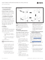
Model Design Configurations
GXT5-500/750/1000/1500LVRT2UXL and GXT5-1000/1500LVRT2UXLTAA
GXT5-2000LVRT2UXL and GXT5-2000LVRT2UXLTAA GXT5-3000LVRT2UXL and GXT5-3000LVRT2UXLTAA
Item Description Item Description
1 VertivTM Liebert® IntelliSlotTM Port 7 Input circuit breaker
2USB port 8Power cable plug
3RS-485 port - Used for external
temperature sensors
9RS-232 port - Used for CLI
4External battery connector 10 Dry contacts, Battery Detection (3), REPO
input (REPO)
5Non-programmable output
receptacles
11 Power cable receptacle
6Programmable output receptacles 12 Ground screw (behind the power plug cable)
13 Output circuit breaker

Vertiv™ Liebert® GXT5 UPS 500-3000VA LV, 120V In, 120V Out
Quick Installation Guide
2 SL-70307_REV5_04-23 PROPRIETARY AND CONFIDENTIAL ©2023 VERTIV GROUP CORP.
Pre-Installation Checks
1. Inspecting the UPS
Visually inspect the UPS for any
damage. If damage is visible, do not
install the unit and call our warranty
support line for assistance at 1-800-
222- 5877 menu option 3, or email at
microups.warrant[email protected]
.
2. Conditions for Installation
Install the UPS in a temperature
controlled environment that is free of
corrosive and conductive
contaminants. Avoid locations near
heat or water sources and exposed to
direct sunlight. For proper ventilation,
leave four inches clearance on all
sides of the UPS. The input outlet
should be nearby and easily
accessible.
Installation
• Installing the UPS:
The UPS and optional external battery
cabinets (EBCs) may be installed in
either a tower or rack configuration.
• For Tower Installation:
1. Assemble the tower support
stands, and spacers if EBCs are
used.
2. Place the UPS, and the EBC if it
is used, on the tower support
stands.
• For Rack Installation:
NOTE: Internal batteries may be
removed from the UPS to be installed
easier.
1. Attach the handles to the UPS
with four screws on each side.
2. Align the rack kit with the
desired rack U number. Install
the rail kit in the rack with two
screws on the front and two
screws on rear of each rail.
3. Install the UPS in the rack.
4. Secure the handles to the rack
with two screws on each side.
NOTE: If internal batteries were
removed, reinstall internal batteries.
NOTE: Do not attempt to rotate the
UPS display. The UPS display content
will automatically adjust based on rack
or tower installation.
Connections
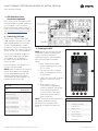
1. Connecting EBC (optional)
EBC provide longer battery run time for
connected devices. Refer to GXT5 User
Guide, to select the appropriate model
and quantity for your GXT5 model and
applications. Refer the figure on the
next page for UPS and EBC
connections.
1. Confirm that the EBC circuit
breaker is in the OFF position
(1a on the image). If multiple
EBCs are used confirm on each
EBC (1b).
2. Connect one end of the
supplied EBC power cable to the
UPS and one end to the top
connector on the EBC (2a). If
connecting more than one EBC,
connect an additional EBC
power cable to the bottom
connector on the first EBC and
to the top connector on the
second EBC (2b). Repeat for
each EBC.
3. Connect one end of the
supplied communication cable
to the UPS dry terminal contact
number 3. Connect the other
end to the top connector on the
EBC (3a). If connecting more
than one EBC, connect an
additional communication cable
to the bottom connector on the
first EBC and the top connector
on the second EBC. Repeat for
each EBC.
2. Network Communication Card
Connection (optional)
Advanced monitoring and simple
control of the Liebert® GXT5 can be
done with the use of a VertivTM Liebert®
IntelliSlotTM RDU101 Communications
card. Visit www.vertiv.com/rdu101 for
additional information. VertivTM Power
Insight can be used as a centralized
monitoring HUB from your computer.
Visit www.vertiv.com/powerinsight for
additional information and to download
the software.
1. Remove the two screws and
protective cover on the rear
panel network communications
port.
2. Insert the card into the port and
secure it with the screws. Refer
to the documentation with the
card or at the link above for
cable connection and operation.
Installing the UPS

SL-70307_REV5_04-23 3
Vertiv™ Liebert® GXT5 UPS 500-3000VA LV, 120V In, 120V Out
Quick Installation Guide
PROPRIETARY AND CONFIDENTIAL ©2023 VERTIV GROUP CORP.
Operation and Display Panel
5. Powering the UPS
NOTE: Do not start the UPS until the
installation has been completed, the
system is commissioned by an
authorized engineer, and the external
input circuit breakers have been
closed.
1. Make sure the panel feeder
breaker supplying power to the
UPS is closed.
2. If an optional POD is installed,
make sure the bypass switch is
in UPS position.
3. If EBCs are connected, close the
breakers on the rear of each
EBC.
4. When the UPS is first
connected startup guidance
screens will appear. Use the Up,
Down, and Enter buttons to
confirm settings. Then, press
and hold the power button to
power on the UPS.
NOTE: The UPS alarm will sound when
the output receptacles are not
powered. Press and hold the Esc
button for 2 seconds to silence the
alarm.
3. USB Communication
Connection (optional)
Basic monitoring of the Liebert® GXT5
and unattended controlled shutdown of
your computer in case of a power
failure can be done using the VertivTM
Power Assist software via the USB port.
Visit www.vertiv.com/powerassist for
additional information.
4. Connecting AC Input
The UPS has a 5-15P, L5-20P (with
5-20P adapter if desired), or a L5-30P
input plug depending on your model.
The UPS is equipped with output
receptacles. Connect the equipment to
be protected to the output receptacles.
Ensure all loads are first powered o.
Connect the input power plug to an
input power supply that is properly
protected by a circuit breaker in
accordance with national and local
electrical codes.
Recommended circuit breakers are
shown in the Wiring table.
NOTE: Allow the batteries to charge at
least 8 hours before first startup to
ensure adequate backup time. The
batteries charge when the UPS is
connected to AC input regardless of
whether the UPS is on or o.
Wiring Table
Model Recommended
External Breaker
GXT5-500LVRT2UXL 12 A
GXT5-750LVRT2UXL
GXT5-1000LVRT2UXL and
GXT5-1000LVRT2UXLTAA
GXT5-1500LVRT2UXL and
GXT5-1500LVRT2UXLTAA
15 A
GXT5-2000LVRT2UXL and
GXT5-2000LVRT2UXLTAA
20 A
GXT5-3000LVRT2UXL and
GXT5-3000LVRT2UXLTAA
30 A
Item Description
1 Run indicator LED
2 Alarm indicator LED
3 Power button
4 Display screen
5 Escape button
6 Up arrow button
7 Down arrow button
8 Enter button
GXT5 UPS and EBC Connections

To contact Vertiv Technical Support: visit www.Vertiv.com, email at liebert.upstech@vertiv.com or call 1-800-222-5877
© 2023 Vertiv Group Corp. All rights reserved. Vertiv™ and the Vertiv logo are trademarks or registered trademarks of Vertiv Group Corp. All other names and logos referred to are trade names, trademarks
or registered trademarks of their respective owners. While every precaution has been taken to ensure accuracy and completeness here, Vertiv Group Corp. assumes no responsibility, and disclaims all
liability, for damages resulting from use of this information or for any errors or omissions.
4 SL-70307_REV5_04-23 PROPRIETARY AND CONFIDENTIAL ©2023 VERTIV GROUP CORP.
-
 1
1
-
 2
2
-
 3
3
-
 4
4


Vertiv Liebert® GXT5 120-V 500-3000VA Quick Installation Guide
- Type
- Quick Installation Guide
Ask a question and I''ll find the answer in the document
Finding information in a document is now easier with AI