
© Bosch Automotive Service Solutions Inc.
Sheet No.
Issue Date: Rev. D, June 5, 2015
Safety Precautions
WARNING: To prevent personal injury,
• Study, understand, and follow all instructions before using this device.
• Wear eye protection that meets ANSI Z87.1 and OSHA standards.
• This tool is designed to be an engine support bar when a transverse axle
or transmission is being repaired or removed. Do not use this tool for any
purpose other than for which it was designed.
• Do not exceed the rated capacity of this tool.
• The vehicle’s lip structure strength must be adequate to support the weight
of the engine; the lip structure surface must be at to prevent slippage of
the engine support bar.
• Stay out from underneath a load that is suspended by a lifting or support
device.
Form No. 537281
Parts List &
Operating Instructions
for: 1725
655 Eisenhower Drive
Owatonna, MN 55060 USA
Phone: (507) 455-7000
Tech. Serv.: (800) 533-6127
Fax: (800) 955-8329
Order Entry: (800) 533-6127
Fax: (800) 283-8665
International Sales: (507) 455-7223
Fax: (507) 455-7063
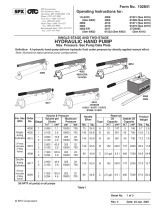
Engine Support Bar
Max. Capacity: 700 lbs.
Item Part No.
No. No. Reqd. Description
1 532525 1 Tube
2 532938 1 Third Arm
Support Bar
3 532936 2 Slide
4 532935 3 Support Stand
5 540863 2 J-Hook
6 538531 1 Socket Wrench
7 541000 2 Sling
8 540670 2 Thrust Washer
9 10208 2 Hex Nut
10 11006 3 Cap Screw
11 537077 3 End Cap
Not Shown
573280 1 Logo/Warning
Decal
1 of 1
1
2
8, 9
3
4
7
11
10
Parts List
Refer to any operating instructions included with the product for detailed information
about operation, testing, disassembly, reassembly, and preventive maintenance.
Items found in this parts list have been carefully tested and selected by OTC.
Therefore: Use only genuine OTC replacement parts.
Additional questions can be directed to our Technical Service Dept. at: 800-533-6127
5
6

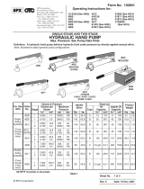
Operating Instructions
Inspect the mounting areas of the vehicle’s lip structure to determine the strongest area in which to mount
the Engine Support Bar. Note: If the engine sags when attached to the engine support bar, adjust the J-hooks
using the socket wrench provided.
Using the Engine Support Bar without the Third Arm Support Bar
Parts List & Operating Instructions Form No. 537281, Sheet 1 of 1, Back
End
Cap
Support
Stand
J-Hook and Slide
Support
Stand
Assemble the engine support bar as shown in
Figure 1.
If the engine has a support bracket, position the
support stand on the vehicle's lip structure and
catch the engine bracket with a J-hook.
If the engine does not have a support bracket,
place the sling around the engine and attach it to
the two J-hooks as shown in Figure 2. Figure 1
Figure 2
J-Hooks
Support
Stand
Support
Stand
Using the Engine Support Bar with the Third Arm Support Bar
Assemble the support bar as shown in Figure 3.
If the engine has a support bracket, position the
support stand on the vehicle's lip structure, rest the
third arm support bar on a solid surface at the front
of the vehicle and catch the engine bracket with a
J-hook.
If the engine does not have a support bracket,
place the sling around the engine, and attach it to
the two J-hooks as shown in Figure 4.
Third Arm
Support Bar
Figure 3
Figure 4
J-Hooks
Support
Stand
Third Arm
Support Bar
End
Cap
End
Cap
End
Cap
End
Cap
-
 1
1
-
 2
2


Ask a question and I''ll find the answer in the document
Finding information in a document is now easier with AI
Related papers
-
OTC 6043 Operating instructions
-
-
-
-
-
-
-
-
-
Other documents
-
Cub Cadet 1811 User manual
-
 IMT 5025 Operation?And Safety
-
 OTC Tools 4000 User manual
-
 OTC Tools 4000 Operating Instructions Manual
-
Generac MTP6500FHKI4P Operating instructions
-
-
Sea Ray 2007 44 SUNDANCER Owner's manual
-
 MacDon D65 Unloading & Assembly Instruction
-
-
Toro CCR 2450 Snowthrower User manual


