
SERVICE MANUAL
PAGE:
1
COLOR TFT-LCD TV
SERVICE MANUAL
MODEL : HLT-3220
CAUTION !!
BEFORE SERVICING THE TFT-LCD TV,
READ THE SAFETY PRECAUTIONS IN THIS MANUAL.

SERVICE MANUAL
PAGE:
2
SAFETY PRECAUTIONS
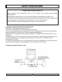
Leakage Current Hot Check (See below Figure)
Plug the AC cord directly into the AC outlet.
Do not use a line Isolation Transformer during this check.
Connect 1.5K/10watt resistor in parallel with a 0.15uF capacitor between a known good earth
ground (Water Pipe, Conduit, etc.) and the exposed metallic parts.
Measure the AC voltage across the resistor using AC voltmeter with 1000 ohms/volt or more
sensitivity.
Reverse plug of the AC cord into the AC outlet and repeat AC voltage measurements for each
exposed metallic part. Any voltage measured must not exceed 0.75 volt RMS, which is,
corresponds to 0.5mA.
In case any measurement is out of the limits specified, there is possibility of shock hazard and
the set must be checked and repaired before it is returned to the customer.
Leakage Current Hot Check circuit
!! Important Safety Notice !!
Many electrical and mechanical parts in this chassis have special safety-related
characteristics.
These parts are identified by in the Schematic Diagram and Replacement Parts List.
It is essential that these special safety parts should be replaced with the same components
as recommended in this manual to prevent Shock, Fire, or other Hazards.
Do not modify the original design without permission of manufacturer.

SERVICE MANUAL
PAGE:
3
SERVICING PRECAUTIONS
CAUTION!!
Before servicing receivers covered by this service manual, read and follow the SAFETY
PRECAUTIONS on page 2 of this publication.
General Servicing Precautions
1.Always unplug the receiver AC power cord from AC power source before;
Removing or reinstalling any component, circuit board module or any other receiver assembly.
Disconnecting or reconnecting any receiver electrical plug or other electrical connection.
Connecting a test substitute in parallel with an electrolytic capacitor in the receiver.
CAUTION!! A wrong part substitution or incorrect polarity installation of electrolytic capacitors
may result in an explosion harzard.
2.Do not spray chemicals on or near this receiver or any of its assemblies.
3.Do not defect any plug/socket voltage interlocks with which receivers covered by this service
manual might be equipped.
4.Always connect the test receiver ground lead to the receiver chassis ground before
connecting the test receiver positive lead. Always remove the test receiver ground lead last.
5.Do not connect the test fixture ground strap to power supply heatsink in this receiver
Electrostatically Sensitive(ES) Devices
Some semiconductor(solid state) devices can be damaged easily by static electricity. Such
components commonly are called Electrostatically Sensitive(ES) Device.Examples
Circuit Board Foil Repair
Excessive heat applied to the copper foil of any printed circuit board will weaken the adhesive
that bonds the foil to the circuit board causing the foil th separate from or “lift-off” the board.
The following guidelines and procedures should be flollowed whenever this condition is
encountered.
At IC Connections
To repair a defective copper pattern at IC connections use the following procedure to install a
jumper wire on the copper pattern side of the circuit board.(Use this technique only on IC
connections.)
1.Carefully remove the damaged copper pattern with a sharp knife.(Remove only as much
copper as absolutely necessary.)
2.Carefully scratch away the solder resist and acrylic coating(if used) from the end of the
remaining coopper pattern.
3.Bend a small “U” in one end of a small guage jumper wire and carefully crimp it around the IC
pin.
4.Route the jumper wire along the path of the out-away copper pattern and let it overlap the
previously scraped end of the good copper pattern. Solder the overlapped area and clip off any
excess jumper wire.

SERVICE MANUAL
PAGE:
4
CONTENTS
Safety precautions ----------------------------------------------------------- 2
Servicing precautions ------------------------------------------------------- 3
Contents ------------------------------------------------------------------------- 4
Specifications ----------------------------------------------------------------- 5
Location of control ---------------------------------------------------------- 9
Deassembly procedure ---------------------------------------------------- 12
Mechanical exploded view with part list ----------------------------- 17
Circuit descriptions --------------------------------------------------------- 18
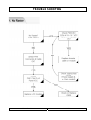
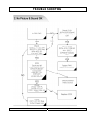
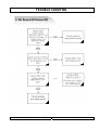
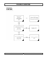
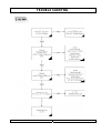
Trouble shooting ------------------------------------------------------------- 51
Wire dressing ----------------------------------------------------------------- 56
Adjustment instruction with SVC mode ------------------------------ 58
Inspection instruction ------------------------------------------------------ 61
PCB Layout --------------------------------------------------------------------- 63
Part appearance -------------------------------------------------------------- 68
Packing instruction ---------------------------------------------------------- 71
Replacement part list -------------------------------------------------------- 73
Block diagram ---------------------------------------------------------------- 83
Connection diagram -------------------------------------------------------- 84
Schemetic diagram --------------------------------------------------------- 85
Wave form --------------------------------------------------------------------- 86

SERVICE MANUAL
PAGE:
5
SPECIFICATIONS
Note: Specifications and others are subject to change without notice for improvement.
1.Scope.
This document is the specification of 32” TFT-LCD Color TV.
2.Power
1) Power requirement
150W
2) AC / DC SMPS
Input Frequency : 50 / 60
Input Voltage: AC 100V- 240V 2.5A ~1.5A
Output Voltage: DC 12V, 24V
3) Power cord
Use UL listed and CSA certified detachable power cord type; SVT, 3-conductors, 18AWG
For AC 120V area. Use VDE listed detachable power cord type; HO5VV-F, 3-conductors,
18AWG for AC 220 240V area.
3.Tuning system
FVS 100 Program
4.Sound output
10W+10Wrms Stereo (Max)
5.Antenna input impedance
VHF / UHF at 75ohm
6.OSD Type (On Screen Display)
Windows type (Center)
7.External in/output
DVI-INPUT,S-VIDEO INPUT,HEADPHONE OUTPUT,ANALOG PC INPUT,PC AUDIO INPUT,
SCART INPUT,SUB WOOFER OUTPUT,AV OUTPUT,ANTENNA INPUT
8. Function
CATV/Hyper band
Auto Program
Manual Program
Auto Sleep
Quick view
ACMS(Auto channel Memory System)
PSM(Picture Status memory)
SSM(Sound Status memory)
PIP(PICTURE IN RICTURE)

SERVICE MANUAL
PAGE:
6
SPECIFICATIONS
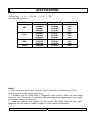
9.Receiving RF TV system
NO
Model System
HLT-3220 / /
1 PAL-B
2 PAL-G
3 PAL-I, I /I
4 PAL-D
5 PAL-K
6 SECAM-B
7 SECAM-G
8 SECAM-D
9 SECAM-K
10 SECAM-K1
11 SECAM-I (6.0)
12 NTSC-3.58 / 4.5
13 NTSC-3.58 / 5.5
14 NTSC-3.58 / 6.0
15 NTSC-3.58 / 6.5
16 NTSC-3.58 / 4.5(5.0)
17 NTSC-4.43 / 5.5
18 NTSC-4.43 / 6.0
19 NTSC-4.43 / 6.5
20 PAL 5.5 / 60Hz
21 PAL 6.0 / 60Hz
22 PAL 6.5 / 60Hz
23 SECAM 5.5 / 60Hz
24 SECAM 6.0 / 60Hz
25 SECAM 6.5 / 60Hz
26 SECAM L / L' X
TOTAL SYSTEM 25

SERVICE MANUAL
PAGE:
7
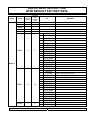
11. PC Mode Scan Frequency & Timing
1) Scan Freq: H: 15 110 kHz / V: 56 75
2) Preset Timing Chart
Mode Resolution H-Freq(KHz) V-Freq(KHz)
VGA
640x480
640x480
640x480
720x400
31.5KHz
37.9KHz
37.5KHz
31.5KHz
60Hz
72Hz
75Hz
70Hz
SVGA
800x600
800x600
800x600
800x600
35.1KHz
37.9KHz
48.1KHz
46.9KHz
56Hz
60Hz
72Hz
75Hz
XGA
1024x768
1024x768
1024x768
48.4KHz
56.5KHz
60.2KHz
60Hz
70Hz
75Hz
WXGA
1280x768 47.7KHZ 60Hz
Note!! :
If the set is cold, there may be a small “flicker” when the set is switched on. This is
Normal, there is nothing wrong with the set.
if possible, use the VESA 1024 x 768@60HZ video mode to obtain the best image
quality for your LCD monitor. If used under the other resolutions, some scaled or processed
pictures may appear on the screen.
SPECIFICATIONS

SERVICE MANUAL
PAGE:
8
13. TFT – LCD Panel Character
1) Feature
Size : 32.0 inches diagonal
LCD Type : a-si TFT Active MatriX
Pixel Pitch : 0.51075mm (H) x 0.51075mm(V) x RGB
Pixel Format : 1366 horiz. By 768 vert. Pixels RGB strip arrangement
Active Video Area : 697.6845mm (H) x 392.256mm (V)
Surface treatment : Anti-glare with anti-reflective coating Hard coating (3H)
Response Time (Typ) : Rising Time : 16ms(TYp), Falling Time : 8ms (Typ)
Viewing Angle<CR≥10> : Hor [Left/Right] Æ 85Deg (Typ) / 85Deg (Typ),
Ver [High (Top)/Low (Bottom)] Æ 85Deg (Typ) / 85Deg (Typ)
Luminance(Typ) : 450 cd/ (Typ)
Contrast Ratio (Typ) : 1000(Typ)
Display Color : 16.7M Color
Back Light : 16 CCFL
SPECIFICATIONS

SERVICE MANUAL
PAGE:
9
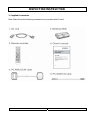
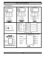
LOCATION OF CONTROL
All the function can be controlled with the remote controller.
Some functions can also adjusted with the buttons on the controls on the TV front panel.
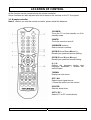
1-1. Remote controller
Note !! : Before you use the remote controller, please install the batteries.
1.POWER:
Turns the TV on from standby or off to
standby mode.
2.MUTE:
Turns the sound on and off
3.NUMBER buttons:
Select channel numbers.
4.PSM (Picture Status Memory):
Recalls your preferred picture setting.
5.SSM (Sound Status Memory):
Recalls your preferred sound setting.
6. I / II:
Selects the language during dual
language broadcast. / Selects the
sound output.
7.MENU:
Displays a main menu.
8.TV / AV:
Selects input signal source.
/ Clears the menu from the screen.
9.SLEEP:
Sets the sleep timer.
10.TV / PC :
Selects TV or PC mode directly.

SERVICE MANUAL
PAGE:
10
LOCATION OF CONTROL
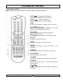
1-2. Remote controller
Note !! : Before you use the remote controller, please install the batteries.
11.PR ( Programme Up/Down):
Selects a next programme or a menu item.
12.VOL ( Volume Up/Down):
Adjusts the sound level or a menu Setting.
13.OK
Accepts your selection or displays the current mode.
14. TELETEXT Buttons:
These buttons are used for TELETEXT. For further
details, see the TELETEXT Selection
.
15. Q.VIEW
Returns to the previously viewed Programme
Note: TELETEXT mode.
The Q.VIEW button is used for TELETEXT function.
16. LIST
Displays the program list menu.
17. PIP
Display a PIP (Picture In Picture) screen.
18. ARC
Selects a screen mode – 16:9, 14:9, ZOOM, 1:1 and
auto Wide.
19. INPUT
Selects the AV source of sub picture in PIP mode.
20. POSITION
Selects a position of PIP screen.
21. SWAP
Switches a main picture for sub picture in PIP mode.
22. MODE
Selects a PIP screen mode – 16:1,9:1,double window
and scan mode
23. PR
Selects a programme when RF signal is displayed in
PIP mode.

SERVICE MANUAL
PAGE:
11
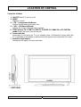
LOCATION OF CONTROL
Controller of Panel
1. ON/OFF Switch TV set on or off.
2. MENU
Displays a menu.
3. + PR – ( programme Up/Down)
Selects a programme or a menu item.
4. + VOL – (Volume Up/Down)
Adjusts the volume./ Adjusts menu settings.
5. TV/AV Selects TV, SCART1, SCART2, S-VIDEO, PC-ANALOG or PC-DIGITAL
mode./Clears the menu from the screen.
6. Power Indicator
Llluminates in red when the TV is in standby mode / llluminates in green when the
TV is switched on.llluminates in blinked when the power save mode(only PC mode)
7. Remote control sensor
Accepts the IR signal of remote controller
< SIDE VIEW>

SERVICE MANUAL
PAGE:
12
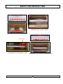
DISASSEMBLY PROCEDURE
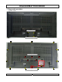
1. Disassembly procedure
1).Back cover
Remove 16 screws
Removal of Backcover
Remove 4 screws
Removal of Stand

SERVICE MANUAL
PAGE:
13
DISASSEMBLY PROCEDURE
2).Metal plate & Rear chassis
Remove 5 screws
Removal of rear metal chassis...
Removal of Terminal metal plate
1. Remove 2 screws
2. Slide away the
metal plate

SERVICE MANUAL
PAGE:
14
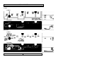
DISASSEMBLY PROCEDURE
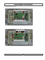
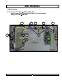
3).Main PWB & Connectors
Remove 4 Main PCB
Removal of Main P CB
Remove 4 Main PCB screws
Removal of Main PCB
Removal of Main PCB
Remove7 connectors
Removal of Main PCB

SERVICE MANUAL
PAGE:
15
DISASSEMBLY PROCEDURE
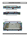
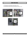
4).LCD Panel chassis
5-1 ) LCD Module
Removal of LCD Module
Remove 11 screws, then take off
Removal of LCD Module
Remove 7 screws, then take off
Remove10 screw
Remove 3 brackets, then lift out LCD Module
(move all wire looms away which are attached to the module)
Removal of LCD Panel module mounting brackets

SERVICE MANUAL
PAGE:
16
DISASSEMBLY PROCEDURE
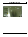
5-2). LCD Moul

SERVICE MANUAL
PAGE:
17
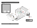
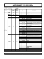
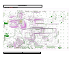
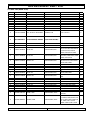
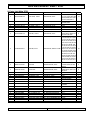
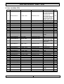
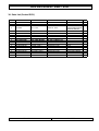
MECHANICAL EXPLODED VIEW
1. Explode View
1
10
2
3
4
5 6
7
8
9
11
12
13
15
16
32
17
20 21
23
24
25
26
27
26
26
26
27
19
30
14
32
32
18
22
32
26
31
27
31
28
28
33
29
Screw point
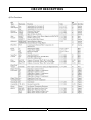
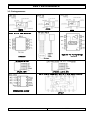
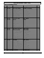
NO PART NO DESCRIP TION MATERKAL COLOR FINISH Q'TY
1 - DECO F RO NT PM M A BLACK 1
2 610-006A SPEAKER
10W
,
8
-2
3 610-006B SPEAKER
10W
,
8
-2
4 400-021F FRONT COVER PC+ABS SILVER,BLACK 1
5 408-002F LENS SENSO R PC TRANSPARENCE 1
6IR PCB--1
7CONTROL PCB--1
8 404-004B BLOCK KNO B ABS SILIVER 1
9 - CONTROL PLATE AL SILIVER 1
10 407-001E F IX B RKT EG I - 2
11 PANV320W 2L01 PANEL SAMSUNG - 1
12 407-005F B RKT L, R EG I - 2
13 407-001Z LCD B RKT EG I - 1
14 620-005D A/C, D/C ADAPTER - - 1
15 - MAIN PCB ASS'Y - - 1
16 - JACK SHIELD SPTH - 1
17 407-002L RE AR SHIELD E G I - 1
18 407-003F BACK CO VER PC+ABS DARK GRAY 1
19 - REAR PLATE PVC BLACK 1
20 401-0032 BO T T O M BRK T EG I - 1
21 450-001Y DE CO ST AND PMM A B LACK 1
22 402-004W ST AND BO T TO M A B S SILV E R 1
23 402-004C ST AND FRONT ABS DARK GRAY 1
24 401-0016 ST AND BRKT E G I - 1
25 402-004D STAND REAR ABS DARK GRAY 1
26 410-001Q BT B 4*12 47
27 410-001K T TB 3*8 8
28 410-001L T T B 3*10 5
29 410-003R PBT B 4*10 4
30 410-002R PP 4*12 4
31 410-001R PB 4*8 10
32 410-001N FT B 3*6 20
33 410-002Q PS 4*10 SNI 3
AYCO LT 32A01C
SCREW TAPPING
SZN
SCREW MACHINE
MATERIAL DATA
2004. 12. 27
THIS ENGR
D. H. KIM
TR EATM ENT GH K
M OD EL APPD SC ALE SHEET
LT32G - 1 / 2
SET Exploded Draw ing
DRAWING NO.
TITLE
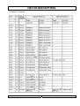
Description

SERVICE MANUAL
PAGE:
18
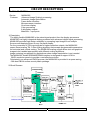
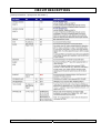
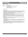
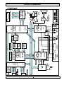
CIRCUIT DESCRIPTIONS
General Description for 32.0” color TFT LCD TV.
The TFT LCD TV described in the followings is based on a Multi TV system, digital
Control display, 32.0” diagonal. The TFT LCD TV is intended to be a finished product,
Basically a display device mounted inside an enclosure which will provide the safety
Requirements. With the exception of LCD Panel, the display device shall be composed
entirely of solid state components.
These components shall have a history of reliable service in identity applications
and shall be applied in the circuits.
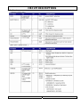
1. SCALER SECTION.
2. MCU SECTION.
3. ADC SECTION.
4. VIDEO PROCESSOR SECTION.
5. AUDIO PROCESSOR SECTION.
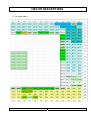
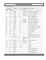
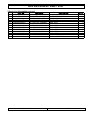
NOTE: development early stage it used the EEPROM – AT29C020
The production used the OTP (EPROM – M27X201)
It follows in the ROM and the point which is changed
Apply ROM
LOCATION NO
PART Insert PART Remove Description
AT29C020 (flash) IC01 L17 L15 600ohm BEAD
M27X201 (OTP) IC01 L15 L17 600ohm DEAD

SERVICE MANUAL
PAGE:
19
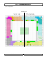
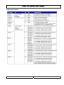
CIRCUIT DESCRIPTIONS
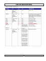
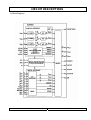
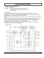
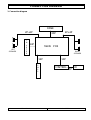
1.SCALER SECTION.
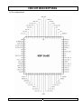
Device: MX88L285
Features: Advanced Image Scaling/ processing
Automatic Image Optimization
Frame buffer interface
Microprocessor interface
On-screen display
Color processing
8-bit display outputs
Main/Sub – input ports
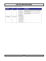
1) Description
The highly flexible MX88L285 is the mixed-signal product from the display processors.
MX88L285 is a highly integrated display processor with advanced digital signal processing.
MX88L285 provides high design scalability by accepting input images from multiple
Sources and displaying them on any flat panel display.
For the conversion of VGA input signals to higher-resolution outputs, the MX88L285
uses a Smart-scaling TM -3 filter scaling algorithm that accepts programmable parameters
for horizontal and vertical scaling. The MX88L285 scaling engine allows text and graphics
images to be handled appropriately with different scaling algorithms.
Image centering is supported for applications where image manipulation is not needed.
The MX88L285 flexible SDRAM/SGRAM interface is designed to support VGA to
WXGA resolution panels to provide a cost-effective solution.
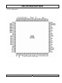
Fabricated in an advanced CMOS process, the MX88L285 is provided in a space-saving
–388-lead PBGA surface-mount plastic package.
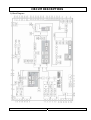
2) Block Diagram.

SERVICE MANUAL
PAGE:
20
CIRCUIT DESCRIPTIONS
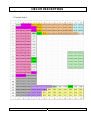
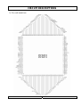
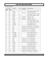
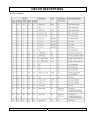
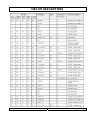
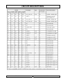
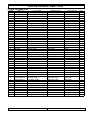
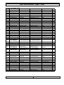
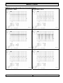
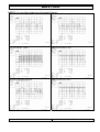
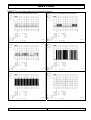
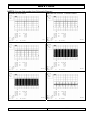
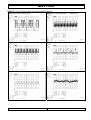
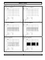
3) Pin configuration.
Reference line
Page is loading ...
Page is loading ...
Page is loading ...
Page is loading ...
Page is loading ...
Page is loading ...
Page is loading ...
Page is loading ...
Page is loading ...
Page is loading ...
Page is loading ...
Page is loading ...
Page is loading ...
Page is loading ...
Page is loading ...
Page is loading ...
Page is loading ...
Page is loading ...
Page is loading ...
Page is loading ...
Page is loading ...
Page is loading ...
Page is loading ...
Page is loading ...
Page is loading ...
Page is loading ...
Page is loading ...
Page is loading ...
Page is loading ...
Page is loading ...
Page is loading ...
Page is loading ...
Page is loading ...
Page is loading ...
Page is loading ...
Page is loading ...
Page is loading ...
Page is loading ...
Page is loading ...
Page is loading ...
Page is loading ...
Page is loading ...
Page is loading ...
Page is loading ...
Page is loading ...
Page is loading ...
Page is loading ...
Page is loading ...
Page is loading ...
Page is loading ...
Page is loading ...
Page is loading ...
Page is loading ...
Page is loading ...
Page is loading ...
Page is loading ...
Page is loading ...
Page is loading ...
Page is loading ...
Page is loading ...
Page is loading ...
Page is loading ...
Page is loading ...
Page is loading ...
Page is loading ...
Page is loading ...
Page is loading ...
Page is loading ...
Page is loading ...
Page is loading ...
Page is loading ...
Page is loading ...
Page is loading ...
Page is loading ...
Page is loading ...
Page is loading ...
-
 1
1
-
 2
2
-
 3
3
-
 4
4
-
 5
5
-
 6
6
-
 7
7
-
 8
8
-
 9
9
-
 10
10
-
 11
11
-
 12
12
-
 13
13
-
 14
14
-
 15
15
-
 16
16
-
 17
17
-
 18
18
-
 19
19
-
 20
20
-
 21
21
-
 22
22
-
 23
23
-
 24
24
-
 25
25
-
 26
26
-
 27
27
-
 28
28
-
 29
29
-
 30
30
-
 31
31
-
 32
32
-
 33
33
-
 34
34
-
 35
35
-
 36
36
-
 37
37
-
 38
38
-
 39
39
-
 40
40
-
 41
41
-
 42
42
-
 43
43
-
 44
44
-
 45
45
-
 46
46
-
 47
47
-
 48
48
-
 49
49
-
 50
50
-
 51
51
-
 52
52
-
 53
53
-
 54
54
-
 55
55
-
 56
56
-
 57
57
-
 58
58
-
 59
59
-
 60
60
-
 61
61
-
 62
62
-
 63
63
-
 64
64
-
 65
65
-
 66
66
-
 67
67
-
 68
68
-
 69
69
-
 70
70
-
 71
71
-
 72
72
-
 73
73
-
 74
74
-
 75
75
-
 76
76
-
 77
77
-
 78
78
-
 79
79
-
 80
80
-
 81
81
-
 82
82
-
 83
83
-
 84
84
-
 85
85
-
 86
86
-
 87
87
-
 88
88
-
 89
89
-
 90
90
-
 91
91
-
 92
92
-
 93
93
-
 94
94
-
 95
95
-
 96
96


