Page is loading ...

Herald 80B 07102013 Page 1
H E R A L D 80B
CE V .II
M U L T I F U E L
C E N T R A L - H E A T I N G
S T O V E
Installation and Operating Instructions
Tested to AS/NZS 2918:2001
Test report 12/2569
WARNING: Improper installation, adjustment, alteration, service or maintenance can cause
injury or property damage. For assistance or additional information consult an authorized
technician, or your Hunter Dealer.
FOR YOUR SAFETY: Do not store or use gasoline or other flammable vapours and liquids
in the vicinity off this appliance. Installation and service must be performed by authorized
personnel.
PLEASE KEEP THESE INSTRUCTIONS FOR FURTHER REFERENCE.
Manufactured in United Kingdom by: Distributed in New Zealand by:
Hunter Stoves Limited Classic Cookers
Aspen House 151 Bramleys Road
Pynes Hill R D 1
Exeter Kaiapoi
Devon, EX2 5AZ Ph. 03 3106534
E Mail: info@hunterstoves.co.nz Email: info@classiccookers.co.nz
Web: www.Hunterstoves.co.uk Web: www.classiccookers.co.nz

Herald 80B 07102013 Page 2
Contents Page No
Technical Specifications Page 3
Assembly Instructions Page 4
Installation Instructions Page 5-13
Operating Instructions Page 14-17
General Maintenance Page 18-19
Stove Spares Page 20-21

Herald 80B 07102013 Page 3
Herald 80B CE V.II Central-Heating
Technical Specification
Stove Mass 218 kg
Wood
Total Efficiency 71.0%
Nominal Heat Output 21.5 KW
Output to Water 12.4 KW
Output to Room 9.1 KW
Mean CO Emission (at 13% O2) 0.38 %
Mean Flue Gas Temperature 368 °C
Flue Gas Mass Flow 19.3 g/s
Ancit
Total Efficiency 69.5 %
Nominal Heat Output 17.0 KW
Output to Water 12.5 KW
Output to Room 4.5 KW
Mean CO Emission (at 13% O2) 0.20 %
Mean Flue Gas Temperature 314 °C
Flue Gas Mass Flow 15.6 g/s
This appliance is not suitable for use in a shared flue
This appliance is suitable for continuous burning

Herald 80B 07102013 Page 4
Assembly Instructions
PLEASE READ THESE INSTRUCTIONS CAREFULLY
It is important that your stove is correctly installed, as Hunter Stoves Limited cannot
accept responsibility for any fault arising through incorrect use or installation.
Important Warning
This stove must not be installed into a chimney that serves any other heating appliance.
There must not be an extractor fan fitted in the same room as the stove as this can cause the stove to
emit fumes into the room.
Flue Collar
Place the Flue Gasket on the top or rear
outlet as required. Place the Flue Collar on
top of the Gasket. Secure to the four locating
tabs, inside the flue outlet, using the M6 nuts
& studs supplied. Fit the 2 - M8 carriage
bolts, washers & nuts into the Damper
Holes, located on each side of the Flue Collar.
Blanking Plate
Fit the Flue Gasket and Blanking Plate on the remaining free outlet and secure it,
using the 2 - M6 screws.
Baffle Removal/Fitting
Lift the Baffle and slide to the
right. When the left side of the
baffle clears the support, lower
the baffle into the Fire Box and
remove. Refit in reverse order
making sure that the back edge
of the baffle is located between
the two baffle supports.

Herald 80B 07102013 Page 5
Installation Instructions
These instructions cover the basic principles to ensure satisfactory installation of the stove,
although detail may need slight modification to suit particular local site conditions. In all cases the
installation must comply with current Building Regulations, Local Authority Byelaws, national
standards and other specifications or regulations as they affect the installation of the stove.
Health And Safety Precautions
Handling
Adequate facilities must be available for loading, unloading and site handling.
Fire Cement
Some types of fire cement are caustic and should not be allowed to come into contact with the skin. In
case of contact, wash immediately with plenty of water.
Asbestos
This stove contains no asbestos. If there is a possibility of disturbing any asbestos in the course of
installation then please seek specialist guidance and use appropriate protective equipment.
Metal Parts
When installing or servicing this stove, care should be taken to avoid the possibility of personal injury.
POSITIONING YOUR FREE-STANDING STOVE (WOODFIRE)
Freestanding stoves (wood fires) must not be installed in a fireplace or alcove, under a ceiling of less
than 2.3m height.
No wall or other fixed object may be closer to the front of the wood fire than one meter.
When fitting a hot water boiler, the wood stove should be close (no more than 10m of Pipe) to the water
cylinder.
Determine the installation position for your wood fire only after considering the necessary
clearances and checking the practicability of installing the flue system.
Regard heat resistant walls with heat sensitive surface treatments (e.g. wallpaper or heat sensitive paints)
as heat sensitive walls.
There must be a 25mm gap between the flues casing (see Installation Specification
Sheets for size) and any combustible material. This space must be available without
the removal of structural beams.
Flue installations other than strictly vertical ones are possible. See AS/NZS 2918 for
Information on non-vertical flues and flues passing through walls and eaves.

Herald 80B 07102013 Page 6
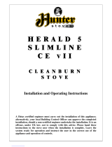
80B Dimensions (in millimetres)

Herald 80B 07102013 Page 7
Installation
Installing the Flue
You MUST use a flue system, which complies with the current installation Standard
AS/NZS 2918.
Full instructions are supplied with the flue kit, and these MUST be followed closely,
including the minimum flue exit height from the top of the floor protector and the
minimum exit height above the roofline or roof ridge as detailed in the instructions.
Always seal the flue to the flue socket of the firebox using firebox cement and/or
fibreglass rope.
Only flue systems tested for the appliance can be used.
The flue system to be used is a spiroloc CCHS175
Other Flue Systems
Flues and flue heat shields other than those listed on the Installation Specification Sheets
may be used, but if they have not been tested with these heaters, their installation
Clearances will be those specified in AS/NZS 2918:2001 for untested flue installations.
Unless otherwise specified, all heat sensitive wall material must be kept at least
600mm away from any flue, which is not fitted with a flue heat shield.
Flue Draught
A flue draught of minimum 1.2mm to a maximum 2.5mm water gauge is required for satisfactory
appliance performance. The flue draught should be checked under fire at high output. If it exceeds the
recommended maximum, a draught stabiliser must be fitted so that the rate of burning can be controlled
and to prevent over firing. If the reading is less than the recommended minimum then the performance
of the appliance will be compromised.
Air Supply
The room or space containing this appliance needs a permanent, unobstructed air opening of at least
9075 mm
2
.
If a draught stabiliser is fitted, the air opening should be at least 15525 mm
2
. Due consideration should
be given to air requirements for any other appliances in the same room or space.

Herald 80B 07102013 Page 8
Material Clearance
Corner Orientation
Where the sides of the stove are at 45 degrees to the walls
Rear corner of the stove to combustibles is 195mm
These clearances can be reduced by using shield as stated in ASNZ 2918:2001
There should be NO combustible material (i.e. furniture) placed within a distance of 1 meter from any
surface of the stove.
Note: combustible material refers to any material that will degrade when subjected to heat e.g.
plasterboard
Normal Orientation
MINIMUM DISTANCE TO COMBUSTIBLE MATERIAL
Behind the stove ( Top Plate)
250mm
At the side of the stove (top Plate)
170mm
195mm from corner of
top hot plate to
combustibles
195mm from corner
of top hot plate to
combustibles
300mm
90mm of concrete or
specified hearth

Herald 80B 07102013 Page 9
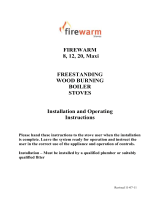
Material Clearances
FLOOR PROTECTOR (Hearth) REQUIREMENTS —
Freestanding models
Unless your wood fire will be standing on an un-covered fireproof floor 90mm of concrete (containing
no combustible material) extending at least 500mm from the appliance, it will be necessary to provide a
floor protector (hearth). See below for construction details. (Fig 1)
Where the minimum size requirements bring the side of the floor protector nearly to a wall, it is
advisable to extend the protector to meet the wall.
This is the only tested floor protection and must be used on timber floors
Raw hearth can be covered in ceramic tiles or bricks.
Fig1
Note: walls are
combustible and all
dimensions stated
are minimum
170 mm from
top hot plate to
combustibles
90mm of concrete or
specified hearth
250mm from top
hot plate to
combustibles
300mm
Optional tile covering
50mm Non Combustible Material
20mm Vacuum formed Board
Timber base board or floor

Herald 80B 07102013 Page 10
Hearth Size
The minimum size hearth for a Herald 80B is 950mm wide with the stove sitting central on the hearth.
The minimum measurement from the front of the hearth to the back of the stove’s bottom plate is
780mm
This measurement gives the minimum hearth requirement of 300mm
Total length of the hearth when no wall shielding is used is 1030mm

Herald 80B 07102013 Page 11
Earthquake Restraints
In New Zealand, Standards require that the wood fire and floor protector be secured to prevent
shifting in the event of an earthquake.
On the hind most legs there are two tabs with 12mm diameter holes for seismic restraint
On a concrete floor installation your Hunter stove is secured by 2 x 10mmx60mm concrete
anchors
Hearth over timber floor installation your Hunter stove is secured by 2 x 10mm diameter coach
screws which are long enough to pass through the hearth and into the timber floor or 2 x 10mm
diameter bolts which are long enough to pass through the floor and all hearth materials and bolt
all together.
INSTALLATION OF BOILER MODELS
We strongly recommend that a knowledgeable, experienced and qualified plumbing and heating
engineer is responsible for the design and installation of the heating and hot water system. Hunter Stoves
Ltd cannot accept responsibility for any consequential loss, however caused, due to under or over
specification of the appliance in any installation.
Do Not – Under any circumstances connect the stove to a sealed (pressurised)
heating system or unvented hot water cylinder.
Do Not – Link the stove into a heating or hot water system with an existing boiler without the use of
suitable equipment such as a neutralizer. When fitting this type of system the neutralizer
manufacturer’s instructions must be followed.
Do – Fit an open cold feed and expansion cistern with separate cold feed and vent pipes. The
cold feed and vent pipes must be unvalved. The open vent pipe should have a diameter of
22mm and rise continuously from the boiler. It is common practice to form the vent pipe
from an extension of the primary flow (see diagram).
Do – Connect the stove to a double feed, indirect hot water cylinder via 28mm copper flow
and return pipework, rising continuously from the boiler to the cylinder. The cylinder and
heat leak radiator must be sited higher than the stove.
Semi pumped systems should be used on heating and hot water systems with gravity circulation to the
hot water cylinder and one unvalved 2 KW radiator to act as a heat leak when the central heating is
switched off.
All four tappings on wraparound boilers should be used for systems incorporating separate gravity and
pumped heating loops. Each flow and return should be taken from diagonally opposite sides of the
boiler.
If a common flow and return is used, these should also be taken from diagonally opposite sides of a
wraparound boiler, and plugs inserted into the sockets not used.

Herald 80B 07102013 Page 12
Room Thermostat
High Limit
Thermostat
90°C
Circulating Pump
Low Limit Thermostat (45°C)
Time Switch
Drain Cock
Room Thermostat
High Limit
Thermostat
90°C
Circulating Pump
Low Limit Thermostat (45°C)
Time Switch
Drain Cock
Injector Tee
Systems using a common flow and return to the boiler should incorporate an injector tee on the primary
return connection from the central heating pump (see diagram).
A HIGH LIMIT thermostat should be fitted to the gravity flow pipe close to the boiler and set at 90°C.
This should override any pump control, switching the pump on and dissipating any excess heat around
the radiator circuit.
To prevent boiler corrosion due to condensation it is necessary to maintain the return water temperature
above 45°C. This can be achieved by the use of a LOW LIMIT thermostat on the return pipe from the
hot water cylinder, close to the boiler. The thermostat should make on temperature rise, preventing the
circulating pump from operating until the gravity circuit is up to temperature.
A corrosion inhibitor must also be added to the system to ensure trouble free boiler performance and
long system life.
Two Tapping System
Four Tapping System

Herald 80B 07102013 Page 13
Commissioning and Handover
Upon completion of the installation, allow a suitable period of time for any fire cement and mortar to
dry out.
A small fire may then be lit and checked to ensure the smoke and fumes are taken from the stove up
the chimney and emitted safely to atmosphere. Do not run the stove at full output for at least 24
hours.
On completion of the installation and commissioning, ensure that the operating instructions and
operating tools for the stove are left with the customer.
Advise the customer on the correct use of the appliance with the fuels likely to be used on the stove
and warn them to use only the recommended fuels for the stove.
Advise the user on what to do should smoke or fumes be emitted from the stove.
The user should be warned to use a fireguard in the presence of children, aged and/or infirm persons.
Wiring Diagram for general guidance only
All electrical work must be carried out by a competent
electrician in accordance with the rules in force and the
instructions provided by the circulating pump and
heating controls manufacturer

Herald 80B 07102013 Page 14
Operating Instructions
This appliance is not suitable for use in a shared flue
This appliance should not be operated with the doors open
Aerosol Sprays
Do not use an aerosol spray on or near the stove when it is alight.
Air Controls
This stove has been designed to burn cleaner and more efficiently than a conventional wood
burning stove. If used correctly this stove will burn far more efficiently than normal with the
obvious notable feature of CLEAN GLASS.
However, for this product to work properly it must be used correctly.
It is essential that the stove has an adequate air supply for combustion and ventilation.
The primary and secondary air inlets must be kept clear from obstruction and blockage.
Air Controls
Primary Air
The thermostat at the rear of the stove controls the
primary air. The door sliders should be kept closed or the
thermostat will not be able to control the fire.
Secondary Air
Secondary air is controlled via the slider above the
doors; it is this “Airwash” that keeps a clean and
uninterrupted view of the fire.
Damper Assembly (Optional)
When the damper is set in the open position the chimney draws at full draught, increasing the
volume of airflow through the stove and flue. Close all other air controls before closing the damper
fully. Shutting the damper restricts the flow, slowing the rate of burning. Close all other air controls
and allow the fire to die down before closing the damper.
Secondary Air Control (Open Right)
Warning! This Appliance will be hot when in
operation and due care should be taken. The
riddling tool may be used to operate the door
handle. Thick gloves could be used to operate
the primary and secondary air controls.
Primary Air Control (Open Outwards)

Herald 80B 07102013 Page 15
Multifuel Grate
Your Hunter Stove is fitted with a locomotive type grate. So that de-
ashing can be carried out cleanly and easily, it is riddled from the
outside of the stove with the doors closed. The grate is designed to
burn both wood and solid fuels.
To burn solid mineral fuels place the operating tool over the riddling
spigot and pull it down towards you. When left in that position, air is
directed under and up through the slots in the firebed, giving the
optimum conditions for burning solid fuels.
It is important that the riddling tool is used to remove the ash to ensure
airflow through the firebed and allow the fire to burn over the entire
area of the grate.
The ashpan should be emptied at least daily and ash should never be allowed to build up over a
period of time as this will result in damage to the fire bars. The flat end of the riddling tool can be
used to carry the ashpan.
To burn wood, push the operating tool up and away from you. When left in this position, air is
restricted through the bed of the fire providing a solid base to build up a bed of ash. Surplus ash
can be removed either by gentle riddling or with a shovel.
It might prove beneficial when burning more reactive fuels to leave the grate in a “neutral”
position, thus directing some under fire air and some over fire air to the firebed.
Notes on solid mineral fuel burning
Solid mineral fuel should be placed in the stove so that there is no more than a 30° incline of the
fuel bed from front to back. It should not be stacked above the rear edge of the baffle as this may
result in damage to the stove.
With a full load of fuel, the stove will need to be refuelled approximately once every 4 hours.
Solid mineral fuel burns most efficiently with the secondary air control in the closed position.
The primary air sliders (or thermostat, if fitted) can then be used to control the burn rate of the
stove.
Always de-ash before refuelling and do not let the ash build up to the underside of the grate bars.
Solid mineral fuel produces ash, which if allowed to build up, will stifle the airflow through the
grate. This will eventually cause the fire to die.
With some solid mineral fuels a residue of burnt fuel or clinker will accumulate on the grate.
Allow the fire to go out periodically to remove this.
Important! - We cannot stress firmly enough how important it is to empty the ashpan regularly.
Air passing through the firebed cools the grate bars. Distortion or ‘burning out’ of the grate bars
is nearly always caused by ash being allowed to build up to the underside of the grate.

Herald 80B 07102013 Page 16
Notes on Wood burning
With a full load of wood, the stove will need to be refuelled approximately once every 1.5 hours.
Wood can be stacked higher in the stove than solid mineral fuel but care must be taken that logs
do not touch or move the baffle.
Wood burns most efficiently with the primary air sliders in the closed position and the secondary
control open. Moving the secondary control will control the burn rate of the stove. If a primary
air thermostat is fitted this should be used to control the burn rate and the secondary air should
only be ‘cracked’ open to keep the glass clean.
Note - primary and secondary air is needed to light the stove, see section entitled ‘Lighting the
Stove’
Wood burns best on a bed of ash and it is therefore only necessary to remove surplus ash from
the stove occasionally.
Burn only dry, well-seasoned wood, which should have been cut, split and stacked for at least 12
months, with free air movement around the sides of the stack to enable it to dry out. Burning wet
or unseasoned wood will create tar deposits in the stove and chimney and will not produce a
satisfactory heat output.
Lighting the Stove
We recommend that you have two or three small fires before you operate your stove at its
maximum heat output. This is to allow the paint to cure steadily and to give a long service life of
the paint finish. During this curing process you may notice an unpleasant smell. It is non-toxic,
but for your comfort we would suggest that during this period you leave all doors and windows
open.
First, load the fire with starting fuel, i.e. paper, dry sticks and/or firelighters in the mode chosen,
either wood or solid mineral fuel.
Light the fire at the base leaving all air controls open. Allow the fuel to reach a steady glow and
build the fire up gradually. Once you have a good fire established across the grate bed, further
fuel can be added as required.
Extended burning
The stove can be banked up for extended burning. When burning solid fuel, empty the ashpan.
Open air controls and let the fire burn brightly for a short period. Refuel and close primary and
secondary air controls, the exact setting required will depend on the fuel used and the chimney
draw so some practice may be necessary. To revive the fire, open the air controls until the fire is
burning brightly de-ash if necessary and refuel. Set air controls as required.
Reduced Combustion
In order to reduce the combustion of the fire to a minimum, close the primary air sliders (or
thermostat if fitted), then close the secondary air slider by moving the handle all the way to the
left. If the controls are left in this position, the fire will receive the minimum of air and will die
down. If you want to revive the fire it is recommended that the primary air control is open first,
and then open the secondary air slider.
Warning! - The stove will remain hot for a considerable time after the fire has been
extinguished.

Herald 80B 07102013 Page 17
Safety notes for your guidance
FIRES CAN BE DANGEROUS – Always use a fireguard in the presence of children, the elderly
or the infirm.
DO NOT OVERFIRE – it is possible to fire the stove beyond its design capacity, this could
damage the stove, so watch for signs of overfiring – if any part of the stove starts to glow red, the
fire is in an overfire situation and the controls should be adjusted accordingly. Never leave the
stove unattended for long periods without first adjusting the controls to a safe setting – careful air
supply control should be exercised at all times.
WARNING – FUME EMISSION
Properly installed and operated, this appliance will not emit fumes. Occasional fumes from
de-ashing and refuelling may occur. Persistent fume emission must not be tolerated.
If fume emission does persist, then the following immediate action should be taken: -
1. Open doors and windows to ventilate room.
2. Let the fire out, or eject and safely dispose of fuel from the appliance.
3. Check for flue chimney blockage and clean if required.
4. Do not attempt to re-light the fire until the cause has been identified and corrected.
If necessary, seek professional advice.
Important! – Do not fit an extractor fan in the same room as this appliance.
IN THE EVENT OF A CHIMNEY FIRE
Raise the alarm to let others in the house know.
Call the Fire Brigade.
Reduce the appliance-burning rate by closing all air controls.
Move furniture and rugs away from the fireplace and remove any nearby ornaments.
Place a fireguard or spark guard in front of the stove.
Feel the chimney breast for signs of excessive heat.
If the wall is becoming hot, move the furniture away. Ensure that the Fire Brigade can gain access
to your roof space in order to check this area for signs of fire spread.

Herald 80B 07102013 Page 18
GENERAL MAINTENANCE
NO unauthorised modification of this appliance should be carried out.
This appliance requires regular maintenance by a competent engineer.
Baffle
This should be removed and cleaned at least once a month to prevent any build up of soot or fly ash
that could lead to blocked flue ways and dangerous fume emission.
If the baffle is removed the chimney/flue way can be swept through the appliance (unless damper is
fitted).
Stove Body
The stove is finished with a heat resistant paint and this can be cleaned with a soft brush. Do not
clean whilst the stove is hot; wait until it has cooled down. The finish can be renovated with
Hunter stove paint.
Glass Panels
Clean the glass panels when cool with Hunter glass cleaner. Highly abrasive substances should be
avoided as these can scratch the glass and make subsequent cleaning more difficult. Wet logs on
heated glass, a badly aimed poker or heavy slamming of the doors could crack the glass panels.
The glass will not fracture from heat.
Door Catch
Should the door catch require adjustment, to maintain the door seal, it is adjustable. By slackening
the locking nut and turning the door handle one turn clockwise, you will achieve a tighter lock
when the door is closed.
Rope
Check the rope around the door and glass. If rope is becoming detached, use Hunter Stoves rope
glue to reattach it. If the rope is in a poor condition, a replacement rope kit may be ordered from
the Hunter Stoves spares range.

Herald 80B 07102013 Page 19
Chimney and Flue ways
It is important that the chimney, flue ways and any connecting flue pipe are swept regularly. This
means at least once a year for smokeless fuels and at least twice a year for wood and other fuels.
The baffle will need to be removed from its supports in order to sweep the chimney (see assembly
instructions).
Only wire-centred sweeps’ brushes fitted with a guide wheel should be used.
If it is not possible to sweep all parts of the chimney through the appliance, ensure there is adequate
access to cleaning doors.
If the stove is fitted in place of an open fire, then the chimney should be swept one month after
installation to clear any soot falls which may have occurred due to the difference in combustion
between the stove and the open fire.
Gaskets
All gasket used on this appliance are produced from a heat resistant material called Manniglas.
Over time you may find that the gasket changes colour. This is due to a reduction in the pigment
used in the manufacture of the product, and is no cause for concern.
Troubleshooting
Fire will not burn
Check that:
1. The air inlet is not obstructed in any way.
2. Chimneys and flue ways are clear.
3. A suitable fuel is being used.
4. There is an adequate air supply into the room.
5. An extractor fan is not fitted in the same room as the stove.
6. Flue draught is above minimum level (see installation instructions).
Fire blazing out of control
Check that:
1. The doors are tightly closed.
2. The air controls are all in the closed position.
3. A suitable fuel is being used.
4. The glass retaining clips are not loose.
5. The door rope seals are in good condition
6. Flue draught is below maximum level (see installation instructions).

Herald 80B 07102013 Page 20
Glass Clip (HHR08/046)
Glass Clip Screw (FSJM05008SS)
STOVE SPARES
Only Hunter Stoves authorised spares should be used with this appliance
RIGHT HAND DOOR
LEFT HAND DOOR
Glass Clip (HHR08/046)
Glass Clip Screw (FSJM05008SS)
Door Glass
(HHR16/005)
Glass Gasket
(HHR16/006)
Right Hand Door
(HHR16/002)
Door Slider (HHR22/042)
Slider Knob (HHR08/045)
Left Hand Door
(HHR16/001)
Door Slider (HHR22/042)
Slider Knob (HHR08/045)
Door Knob (HCR06/059)
Washer (FWFM08025)
Catch Shaft (HHR08/111)
Circlip (FLRX07)
M8 Full Nut (FNFM08)
Catch (HMSS04/037)
Door Glass
(HHR16/005)
Glass Gasket
(HHR16/006)
/