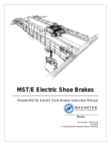
DT Heavy Duty Disc Brakes
Mondel DT Heavy Duty Disc Brakes Instruction Manual
Part Number: 560005-R1
February 2006
© Copyright 2006 Magnetek Material Handling

SUPPLEMENTS FORMING PART OF THIS MANUAL:
DATE OF MANUFACTURE:
APPLICABLE DIMENSION PRINT:
EXPLODED VIEW:
PARTS LIST:
6/7/2006 Page 2 of 17 DT Heavy Duty Disc Brakes Manual
560005-R1
Installation and Maintenance
Instructions
DT Heavy Duty Disc Brakes

Table of Contents
Chapter 1.0: DT Heavy Duty Disc Brakes Warnings and Cautions....................................................4
Chapter 2.0: General Description........................................................................................................6
Chapter 3.0: Installation ......................................................................................................................8
Chapter 4.0: Adjustment....................................................................................................................10
Chapter 5.0: Actuator Delay Adjustment (Optional Feature) Refer to Fig. 5 ....................................14
Chapter 6.0: Operational Test...........................................................................................................15
Chapter 7.0: Inspection and Maintenance ........................................................................................16
6/7/2006 Page 3 of 17 DT Heavy Duty Disc Brakes Manual
560005-R1
Chapter 8.0: Brake Pad Replacement Refer to Fig. 6.......................................................................17

Chapter 1.0: DT Heavy Duty Disc Brakes Warnings and Cautions
These instructions contain safety recommendations for users. Read and follow the information
contained in these instructions and any standards referred to.
If a brake is not installed immediately, it may require protection. For long-term storage, consult
factory for details.
Chapter 3: INSTALLATION – Warnings and Cautions
Anyone involved in the installation or service of this brake must have:
• Received specific training.
• Had experience on similar equipment.
• Knowledge of the equipment on which the brake is installed.
• The ability to understand the terminology.
• The ability to understand the diagrams.
Do not proceed unless technically qualified for the work involved.
Ensure that all suspended loads or systems, subject to the effects of gravity, wind or otherwise,
having the potential of causing the mechanism to move when the brake is released, removed, or
being worked on, are blocked or supported in a satisfactory manner, totally independent of the
brake.
Hazardous voltage can cause burns, injury, or death. Consult the diagrams to identify and switch
off, lock open, and tag the appropriate disconnecting devices. This includes all power to the
brake, drive, control, heating or other related circuits. Verify by testing for voltage and try the
operational controls to prove that all power sources are isolated.
The design of the support structure must be engineered to take the load and reaction when the
maximum torque of the brake is applied. The duty cycle and all special considerations must be
taken into account and an appropriate safety factor applied.
Do not alter the brake to achieve the required alignment, otherwise the integrity of the brake may
be compromised and a replacement brake may not fit.
Excessive run-out or “High Spots” on a brake disc can cause localized and unnecessary heating
and unequal expansion. This may result in severe and permanent damage to the brake disc.
Other factors can contribute to excessive run-out which cannot be detected at low speeds, typical
are bearing wear or the effect of critical shaft speed.
Aligning the calipers accurately to the disc in the plan view will maximize lining life and ensure
that rated performance can be achieved with a minimum of bedding.
6/7/2006 Page 4 of 17 DT Heavy Duty Disc Brakes Manual
560005-R1

Chapter 4: ADJUSTMENT – Warnings and Cautions
It is the users responsibility to determine the torque required from the brake and to ensure the
brake is set to provide the torque required for the application.
Chapter 6: OPERATIONAL TEST – Warnings and Cautions
Unexpected movement, dropped loads or hazardous voltage can cause burns, injury or death.
Make sure the following have been tested prior to the Operational Test:
• Torque set properly.
• Time Delays set properly (if supplied).
• Brake secure, and aligned properly.
• Electrical controls installed and adjusted.
Chapter 7: INSPECTION AND MAINTENANCE – Warnings and Cautions
To allow for expansion of the working fluid, do not over fill the Actuator. Thoroughly clean-up all
spills to aid in quickly detecting new leaks.
6/7/2006 Page 5 of 17 DT Heavy Duty Disc Brakes Manual
560005-R1

Chapter 2.0: General Description
2.1: The Mondel DT brake is a single caliper disc brake, consisting of spring applied, electro-hydraulic
actuator released brake mechanism. See Fig. 1A and 1B.
2.2: The caliper unit is complete with lined pads, spring mechanism, Hy-thrust actuated release
mechanism, manual release, automatic wear compensation (AA), and automatic equalization of
running clearance (AE). When specifically ordered, the brake can be furnished with limit switches
to indicate specific functions.
2.3: Operation of the brake may be enhanced to suit specific applications by the use of optional
adjustable time delay valves installed within the actuator. The (S) delay is used to delay the
return stroke of the actuator on de-energization and will result in a delay in the brake application.
This feature can also be used to delay subsequent brakes until the first of multiple brakes has
been applied. The (H) delay can be used to delay the release of the brake. A typical application
would be where the drive torque will build-up gradually and brake release must be delayed to
prevent “run-back”.
2.4: The brake can be used in conjunction with a Mondel “Braketronic” controller or can be equipped
with hydraulic over-rides.
Figure 1A
6/7/2006 Page 6 of 17 DT Heavy Duty Disc Brakes Manual
560005-R1

Figure 1B
6/7/2006 Page 7 of 17 DT Heavy Duty Disc Brakes Manual
560005-R1

Chapter 3.0: Installation
3.1: Care taken when installing the brake will ensure maximum operational life.
3.2: After unpacking, visually inspect the brake to ensure that damage has not occurred during
shipment and that there are no damaged or missing parts.
3.3: Prepare and align the brake support structure ready to receive the brake. Detailed dimensions
are shown on the certified dimension prints. The support structure must satisfy three
requirements as follows:
3.3.(a): Height or elevation – the brake support structure must present a level, rigid mounting
surface (brake seat) at an elevation compatible with the base of the brake, with a reasonable
shimming allowance of not less than 0.030”.
3.3.(b): Plan location – The bolt holes for securing the brake to the base must be positioned
accurately to ensure brake alignment in both the axial and transverse directions.
3.3.(c): Base Skewing – The bolt holes, for fixing the brake to the brake seat, must be positioned
to ensure the brake can be installed and secured with the brake pads in full contact with the disc.
Ensure there is adequate clearance between the mounting bolts and the base bolt holes, to allow
the alignment of the pads to the disc. A disc brake is particularly susceptible to this type of
misalignment.
3.4: The basic installation procedure is as follows:
3.4.(a): Install the brake disc and hub assembly on the drive shaft.
3.4.(b): Using a dial gauge indicator, check that disc “run-out” is within acceptable tolerance over
the entire braking surface. We suggest a maximum run-out of 0.0005” per inch of disc diameter,
to a maximum of 0.010”.
3.4.(c): Install the caliper assembly on the equipment base. Verify the securing bolts are
centered within the holes in the base and that the base is located correctly with respect to disc.
Temporarily fit two of the bolts to secure the base to the equipment seat.
3.4.(d): Using the manual release, open the pads to maximize clearance on the brake disc.
Adjustment of the Automatic Adjustment (AA) may be necessary.
3.4.(e): Apply additional shimming (if required) between the support seat and the base, as
required, to raise the caliper such that the pads are centered on the horizontal axis of the disc.
3.4.(f): Make sure there is sufficient margin left on the disc face on each side of pad carriers, to
permit the pad carriers to move laterally within their allowable side tolerance and not overhanging
the disc edge. Ensure that there is no possibility that the pads can wear and leave a ridge on the
lining.
3.4.(g): Ensure the axial (along the shaft) location of the brake is correct with respect to the disc.
When the disc is centrally aligned with slot in the brake base, the location of the base is correct.
3.4.(h): Cancel the manual release to apply the pads to the disc with at least the rated torque
setting. This is to ensure that the pads are correctly aligned to the disc and will bring the brake
assembly into alignment. The brake can be set and released several times to ensure alignment.
6/7/2006 Page 8 of 17 DT Heavy Duty Disc Brakes Manual
560005-R1
3.4.(i): It should now be possible to enter all of the “caliper to base” bolts without interference
with the holes. Now the caliper to base bolts can be tightened until snug.

3.4.(j): Before torquing the caliper to base securing bolts, screw in the remaining “base to brake
seat” bolts. If the pad to disc alignment has not changed, torque all bolts as required and then
verify all alignment criteria one more time.
3.4.(k): Preliminary operating adjustments were made at the factory on the basis of rated values
or to meet specific instructions from the purchaser. The user is urged to verify his requirements
and make final torque settings before putting the brake into service. See Fig. 3.
3.4.(l): Unless specifically requested and detailed on previously approved diagrams, all wiring,
control logic, and sequencing of the brake(s) is the responsibility of the user. Verify that the
electrical nameplate ratings are compatible with intended power source.
3.4.(m): Because the operation of the actuator is not dependent on the direction of motor
rotation, the cable leads can be connected in any phase sequence. A wiring diagram is shipped
inside the actuator junction box cover.
3.4.(n): When the brake has been installed as detailed in chapter 3, it is then ready for
adjustment as covered in chapter 4.
6/7/2006 Page 9 of 17 DT Heavy Duty Disc Brakes Manual
560005-R1

Chapter 4.0: Adjustment
4.1: Preliminary adjustments were made at the factory, but may have been disturbed during
installation. All adjustments should be verified or optimized to suit your specific requirements; this
is most critical in reference to the torque setting.
4.2: There are two interdependent steps to achieve correct adjustment for each caliper:
1) Ensuring that the actuator is at the correct stroke with the brake applied.
2) Setting the required torque with the brake applied.
The process of making these adjustments may affect the other, such that it may be necessary to
repeat the procedure until both adjustments are in harmony and also correct on their own. The
essential requirements are:
A) The pads are in full contact with the disc.
B) The actuator is set at the correct stroke.
C) The spring is at the correct length for the required torque as indicated on the scale. The
torque is indicated on the scale by the position of the bottom of the spring (top of the block).
Fig. 2 shows the actuator stroke divided into two zones – the “active” stroke and the “reserve”
stroke and their relationship to the “brake applied” and “brake released” positions.
The “RESERVE” stroke is provided to ensure spring pressure is available to provide the intended
torque when the brake is applied.
The “ACTIVE” stroke is required to ensure adequate running clearance is available when the
brake is released. With the (AA) feature installed the “RESERVE” stroke is approximately 30% of
the total stroke. The precise “RESERVE” stroke will be determined by the (AA) mechanism as
predetermined in the factory, but provisional setting dimensions are as follows:
0.6” (16mm) for type Ed23/5 or Ed30/5 actuators.
0.7” (19mm) for type Ed50/6 through Ed301/6 actuators.
The indicated torque is only valid in the brake-applied position.
4.3: To set the actuator stroke and brake torque in the correct range for the automatic compensation
mechanisms to work successfully, requires a provisional manual adjustment of the actuator
stroke.
The actuator stroke must be correct and the brake “applied” before attempting to adjust
the brake torque.
4.3.(a): Adjustments to the ACTUATOR stroke may be made as follows:
A) Release the brake.
B) Refer to Fig. 4.
C) Withdraw the lock-pin (B), If the actuator is to be raised, first release the brake, rotate the
assembly clockwise by means of the bronze drive shaft (C). Turn the drive shaft “C” by hand.
D) If the actuator is to be lowered – rotate the assembly counter-clockwise by means of the
bronze drive shaft “C”.
E) Replace pin B and secure.
No tools are required to make adjustments to the AA mechanism if the brake is released before
adjustments are attempted.
6/7/2006 Page 10 of 17 DT Heavy Duty Disc Brakes Manual
560005-R1
The drive pin (B) must be removed before any manual adjustments to actuator stroke are
attempted. Failure to remove the pin before attempting manual adjustment may result in

permanent damage to the mechanism. The brake must be released before making manual
adjustments to the actuator stroke.
4.3.(b): Following initial setting of the actuator stroke, the “TORQUE” setting may be made as
follows:
A) Refer to Fig. 3.
B) Observe the present setting.
C) If the torque setting is to be increased rotate the torque adjustment rod (D) clockwise until the
top of the collar/bottom of the spring coincides with the desired torque.
D) If the torque setting is to be decreased rotate the torque-adjusting rod (D) counter-clockwise
until the top of the collar/bottom of the spring coincides with the desired torque.
Adjustments to the torque setting may affect the actuator stroke and vice versa. Any
changes to one setting require verification that the other has not changed.
4.4: This brake is also equipped with AUTOMATIC EQUALIZATION OF OPERATING CLEARANCE
(AE). The feature is designed to maintain the correct running clearance between the pads and
disc when the brake is released. Refer to Fig. 2.
4.4.(a): When the actuator is powered the rod extends from the “BRAKE APPLIED” to the
“BRAKE FULLY RELEASED”. In so doing, it determines the total available running clearance.
Refer to Fig. 2 and Fig. 1B.
4.4.(b): The operating clearance, resulting from the actuator stroke and the arrangement of the
linkage, is biased to provide all of the available running clearance at the pad opposite the
actuator.
4.4.(c): To distribute the available running clearance, so that an adequate amount is available on
both pads, a mechanism is installed which limits the clearance permitted on the pad opposite the
actuator. This device transfers the remainder of the available clearance to the other pad.
4.4.(d): The allowable running clearance on each pad is predetermined at the factory and cannot
be changed in the field.
4.4.(e): Operation of the (AE) mechanism is dependent on the correct setting of the friction bolts
Fig. 2 (F), which will maintain the running clearance regardless of lining wear. This is a factory
setting and should not require adjustment.
4.5: The adjustment procedure should now be complete but as the various phases are
interdependent, it is a good idea to run through them again from 4.1.
6/7/2006 Page 11 of 17 DT Heavy Duty Disc Brakes Manual
560005-R1

Figure 2
6/7/2006 Page 12 of 17 DT Heavy Duty Disc Brakes Manual
560005-R1

Figure 3
Torque Adjustment
Figure 4
Lining Wear Self-Adjustment Assembly
6/7/2006 Page 13 of 17 DT Heavy Duty Disc Brakes Manual
560005-R1

Chapter 5.0: Actuator Delay Adjustment (Optional Feature) Refer to Fig. 5
5.1: The following describes features, which may not be installed on your brake unless specifically
ordered.
5.1.(a): “S” – RETRACT DELAY VALVE – used to delay the actuator return stroke and therefore
the brake application time. Turn clockwise to increase time from minimum to maximum.
5.1.(b): “H” – EXTEND DELAY VALVE – used to delay the actuator advance and therefore the
brake release time. Turn clockwise to increase time from minimum to maximum.
Due to the possibility of causing unnecessary motor heating and brake wear, this feature
is not recommended and is only provided on special order. Unless specific instructions
are provided for adjusting this valve, we recommend that it be kept in the “fully open”
position.
5.2: Adjustments are accessible through removable caps located immediately above the actuator
terminal box and identified by raised letters in the casting.
5.3: After making the required adjustments, re-install the removable access caps. Do not unscrew
either adjustment beyond being flush with the edge of the access hole, as this may prevent the
caps from being refitted or it could cause a leak.
Figure 5
6/7/2006 Page 14 of 17 DT Heavy Duty Disc Brakes Manual
560005-R1
ACTUATOR
ROD (R)
VA LVE (S)
VA LV E (H )
HY-THRUST
ACTUATOR

Chapter 6.0: Operational Test
6.1: Always perform an operational test of the brake after installation, adjustment, or repair. Conduct
the test only when it is safe to do so and keep all personnel well away from any live or moving
parts while testing.
6.2: Conduct all tests in conjunction with the instructions provided by the overall machinery
manufacturer.
6/7/2006 Page 15 of 17 DT Heavy Duty Disc Brakes Manual
560005-R1

Chapter 7.0: Inspection and Maintenance
7.1: It is recommended that brake installations be inspected every 100 hours of operation or at least
every month. This should include visual inspection of the entire brake for evidence of mechanical
failures, misalignment, or other effects. Also check the mounting bolts to ensure that they are
tight.
7.2: Maintenance and inspection periods depend on the operating conditions. High duty cycle
applications obviously require more frequent inspections.
7.3: Pivot points are fitted with special bearings, which do not require lubrication.
7.4: In addition to the instructions listed here, follow the maintenance and safety procedures.
7.5: The standard actuator is supplied for a temperature range from –25C to +50C and filled with
Mondel type C10 fluid. A change in working temperature range may require special fluid.
7.6: The actuator’s oil is not subject to deterioration during normal operation.
7.7: Signs of fluid leakage will usually be evidence of a problem. If this occurs, it is best to purchase a
replacement actuator or have it factory rebuilt.
During refilling, the actuator must be filled in the vertical position and fluid added up the overflow
screw, or the filling limit of the charging connection, depending on the type of actuator. In order
to prevent possible inclusions of air, run the unit through several strokes. Then check oil level
again, and top up eventually. Finally, tighten charging connection and overflow screw.
When the brake is to be repainted,
DO NOT PAINT – pivot points, self adjustment mechanism,
pull-rod, actuator piston rod, brake drum, linings, data plates and labels. Data plates and labels
must never be removed.
6/7/2006 Page 16 of 17 DT Heavy Duty Disc Brakes Manual
560005-R1

Chapter 8.0: Brake Pad Replacement Refer to Fig. 6
8.1: Brake pads must be replaced when thickness (M) is less than 0.2”.
8.2: Subject to the preceding warning when the pads require replacement – release the brake as
follows: Ref. To Fig. 4.
8.2.(a): Release retractable plunger (B).
8.2.(b): Release the brake.
8.2.(c): Unscrew the drive shaft (C) until the brake is completely open.
8.2.(d): The self-adjustment mechanism is factory set and must not be altered.
8.2.(e): Remove the securing bolts (N).
8.2.(f): Remove pad backing plate (P) from above.
8.2.(g): Install new pads (P) and fasten two bolts (N).
8.2.(h): Re-adjust the “Actuator Stroke” as specified in chapter 4 “Adjustment”.
8.2.(i): To ensure the required brake torque and performance, it is necessary to use only pads
provided by Mondel.
8.2.(j): The pad will require a bedding period to develop full torque.
Figure 6
6/7/2006 Page 17 of 17 DT Heavy Duty Disc Brakes Manual
560005-R1
P
N
M
/