Page is loading ...

SPREAD LAVATORY
FAUCETS
Installation
Instructions
6500
6501
6502
6530
6531
6532
Thank you for selecting American-Standard...
the benchmark of fine quality for over 100 years.
To ensure that your installation proceeds smoothly--
please read these instructions carefully before you begin.
Certified to comply with ANSI A112.18.1
1
GOOSE NECK
SPOUT (POP-UP)
CONVENTIONAL SPOUT
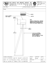
Insert SPOUT SHANK (1, 1a) through
center hole of SINK, making sure
RUBBER GASKET (2, 2a) is properly positioned.
CONVENTIONAL OR GN SPOUT ASSEMBLY
Assemble RUBBER WASHER (3),
RETAINER (4) and LOCKNUT (5) onto
threads of SPOUT SHANK (1, 1a) from
underside of SINK.
Insert LIFT ROD (6, 6a) through SPOUT
and slot of BRASS WASHER (4).
Align SPOUT and tighten LOCKNUT (5).
Be sure slot in BRASS WASHER (4) is
positioned to the rear as shown.
Turn off water at
main supply.
CAUTION
SINK
SLOT
SINK
SLOT
GOOSE NECK
SPOUT
10
3
5
5/16'' MIN.
MOUNTING SURFACE
11
11
1
2
3
1
2
1
3
4
6
6a
5
3
4
5
2
2a
2
Push TUBING (4) ends into VALVE (5) side outlets. Insert VALVES (5)
into mounting holes from underside of ledge.
Install LOCKNUTS (1), BRASS WASHERS (2) and RUBBER WASHERS (3) onto valve shanks.
Place RUBBER RING (11) into DECK ADAPTERS (10) and thread onto
valves until snug against internal stop.
Tighten LOCKNUT (1) to secure VALVE (5) position.
Slide FERRULE (13) and COUPLING NUT (14) to outlet of VALVE (5) and tighten
COUPLING NUT (14) firmly.
Connect HOT water supply to inlet of left VALVE and COLD water supply to inlet of
right VALVE using appropriate connector.
VALVE ASSEMBLY
HOT
COLD
13
5
14
8
7
9
6
14
13
4
5
10
MOUNTING
LEDGE
11
10
Press TEE (6) onto SPOUT SHANK (7) making certain that the O-RING (8) is
properly seated on SHANK (7). Push COUPLING (9) into TEE (6) and
attach to SPOUT SHANK (7) and tighten.
1a
60186 REV.1.5 (2/15)

DRAIN INSTALLATION
3
(Models 6801 and 6831 only)
Push TAILPIECE (1) down into TRAP (2)
(threaded end up).
Thread LOCKNUT (3), WASHER (4) and
GASKET (5) onto DRAIN BODY (6).
Apply a bead of PUTTY to underside
of FLANGE (7).
Feed DRAIN BODY (6) up through SINK
and thread FLANGE (7) fully onto BODY (6).
Tighten LOCKNUT (3) firmly, keeping the
PIVOT ROD (8) pointed towards the back
of the SINK.
Drop STOPPER (9) into DRAIN BODY (6).
Pull TAILPIECE (1) up and thread tightly
into DRAIN BODY (6).
Position EXTENSION ROD (10) onto POP-UP
ROD (11) and tighten THUMBSCREW (12).
Remove one end of CLIP (13) from PIVOT ROD (11)
by squeezing ends together while sliding.
Insert PIVOT ROD (14) into second or third hole
in EXTENSION (10) and reassemble CLIP (13).
(EXTENSION (10) may need to be bent.)
Adjust STOPPER (9) height by repositioning
EXTENSION (10) and tightening THUMBSCREW (12).
SINK
PUTTY
TEST INSTALLED FAUCET
6
Remove AERATOR.
Turn VALVES (1) to off position.
Insert ADAPTOR (8) with larger
diameter over the VALVE STEM (4).
Align LEVER (2) or WRIST
BLADE HANDLE (3) and install
onto VALVE STEM (4).
Insert BLUE INDEX (5) into
cold valve (right side) and red
INDEX (6) into hot valve (left side).
Insert HANDLE SCREW (7) into
HANDLES and tighten with
screwdriver.
With handle in OFF position, turn on water supplies and check
all connections for leaks.
Operate both handles to flush water lines thoroughly. Check
spout mounting and TEE connections for leaks.
Turn handles into OFF position and replace AERATOR.
Apply a bead of PUTTY around underside
of DRAIN FLANGE (1) flange. Insert DRAIN
PLUG (2) into SINK drain hole.
Hold DRAIN PLUG (2) to prevent turning and
assemble GASKET (3), WASHER (4), and
LOCKNUT (5) from underneath sink.
Apply sealant to threaded end of TAILPIECE
and thread into lower end of DRAIN PLUG.
Connect other end to trap.
DRAIN ASSEMBLY (6542.140/.170)
PUTTY
SINK
SEALANT
4
INSTALL HANDLES
5
SERVICE
7
CARTRIDGE
SCREEN
To change direction of handle rotation,
proceed as follows:
Turn valve to OFF position.
Remove HANDLE and BONNET NUT.
Remove SPRING CLIP.
Lift STOP WASHER, turn 90° and replace.
Replace SPRING CLIP.
Replace BONNET NUT, HANDLE, SCREW,
and INDEX.
AERATOR may accumulate dirt causing distorted and reduced
water flow. Remove AERATOR and rinse clean.
If spout drips, operate handles several times from OFF to ON
position. Do not force - handles turn only 90°.
Plastic SCREEN in CARTRIDGE may accumulate
dirt causing reduced water flow. To clean, first
turn off hot and cold water supplies, then:
Remove HANDLE and BONNET NUT.
Remove CARTRIDGE by pulling up.
Thoroughly rinse plastic SCREEN at
base of CARTRIDGE.
Replace CARTRIDGE until flange is
tight against valve body.
Turn valves OFF.
Replace BONNET NUT, HANDLE, SCREW
and INDEX.
SPRING
CLIP
STOP
WASHER
90°
1
3
4
5
6
4
2
1
2
DO: SIMPLY RINSE THE PRODUCT CLEAN WITH CLEAR WATER. DRY WITH A SOFT COTTON FLANNEL CLOTH.
DO NOT: DO NOT CLEAN THE PRODUCT WITH SOAPS, ACID, POLISH, ABRASIVES, HARSH CLEANERS, OR A
CLOTH WITH A COARSE SURFACE.
CARE INSTRUCTIONS:
3
5
7
6
7
1
2
3
4
5
6
7
8
9
10
11
12
13
14
AERATOR
60186 REV.1.5 (2/15)
8

912711-0070A
O-RING
024220-0070A
COUPLING NUT
012683-0020A
CONVENTIONAL SPOUT
WITH POP-UP DRAIN
012683-0020A
CONVENTIONAL SPOUT
LESS DRAIN
030256-0070A
SPOUT MOUNTING KIT
033757-0070A
TEE MOUNTING KIT
012111-0070A
TUBE & TEE KIT (8" CENTERS)
066064-0070A
TUBE & TEE KIT (12" CENTERS)
012112-0070A
TUBE SEAL &
COUPLING KIT
051210-0020A
LEVER HANDLE
951764-0070A
CARTRIDGE
051212-0020A
ESCUTCHEON KIT
051213-0070A
VALVEMOUNTING KIT
028757-0070A
SPOUT GASKET
028617-0020A
POP-UP ROD
904939-0020A
BONNET NUT
051217-0020A
WRIST BLADE
HANDLE
051211-0070A
INDEX KIT
912711-0070A
O-RING
030256-0070A
SPOUT
MOUNTING KIT
A911748-0020A
SPOUT GASKET
012086-0020A
POP-UP ROD
912711-0070A
O-RING
030256-0070A
SPOUT
MOUNTING KIT
A911748-0020A
SPOUT GASKET
051322-0020A
VANDAL PROOF SCREW
000690-0020A
HANDLE SCREW
066116-YYY0A
DRAIN STOPPER
EXTENSION ROD
TAILPIECE INSERT
066117-YYY0A
FLANGE KIT
072574-0070A
070847-0070A
CLIP
066118-0070A
PIVOT ROD
900864-0070A
DRAIN BODY
066497-0020A
COMPLETE
DRAIN BODY
070532-0070A
TAILPIECE
For toll-free information and answers to your questions, call:
1-800-442-1902
Weekdays 8:00 a.m. to 6:00 p.m. EST
IN CANADA 1-800-387-0369 (TORONTO 1-905-306-1093)
Weekdays 8:00 a.m. to 7:00 p.m. EST
IN MEXICO 01-800-839-1200
Product names listed herein are trademarks of American Standard Inc.
© AS America, Inc. 2009
HOT LINE FOR HELP
SPREAD LAVATORY
FAUCETS
MODEL NUMBERS
015025-YYY0A
DRAIN COMPLETE
070532-0040A
TAILPIECE
000690-0020A
HANDLE SCREW
051211-0070A
INDEX KIT (PAIR)
6500
6501
6502
6530
6531
6532
60186 REV.1.5 (2/15)
M922880-0020A
AERATOR, 1.5gpm/5.7L/min.
066074-0070A
VR AERATOR, 0.5gpm/1.9L/min.
M922858-0020A
VR AERATOR, 0.35gpm/1.3L/min.
M922880-0020A
AERATOR,
1.5gpm/5.7L/min.
066074-0070A
VR AERATOR,
0.5gpm/1.9L/min.
M922858-0020A
VR AERATOR,
0.35gpm/1.3L/min.
M922881-0020A
AERATOR 1.5 GPM
066508-0020A
AERATOR 0.5VR GPM
M922286-0020A
AERATOR 0.35 GPM
M918014-0070A
ADAPTER
M918014-0070A
ADAPTER
/