Page is loading ...

18-HD72D1-6
TCONT824 Installation Guide
Trane XL824
Connected Control
ALL phases of this installation must comply with NATIONAL, STATE AND LOCAL CODES
IMPORTANT — This Document is customer property and is to remain with this unit.
These instructions do not cover all variations in systems or provide for every possible contingency to be met in connection with
the installation. Should further information be desired or should particular problems arise which are not covered sufficiently
for the purchaser’s purposes, the matter should be referred to your installing dealer or local distributor.
WORKS WITH

Installation Guide
2 18-HD72D1-6
1. Safety
NOTE: Use 18-gauge color-coded thermostat cable for
proper wiring. Shielded cable is not typically required.
Keep this wiring at least one foot away from large inductive
loads such as Electronic Air Cleaners, motors, line starters,
lighting ballasts and large distribution panels.
Failure to follow these wiring practices may introduce
electrical interference (noise) which can cause erratic
system operation.
All unused thermostat wire to be grounded at indoor unit
chassis ground only. Shielded cable may be required if the
above wiring guidelines cannot be met. Ground only one
end of the shield to the system chassis.
▲
WARNING
!
This information is intended for use by individuals
possessing adequate backgrounds of electrical and
mechanical experience. Any attempt to repair a central
air conditioning product may result in personal injury and/
or property damage. The manufacturer or seller cannot
be responsible for the interpretation of this information,
nor can it assume any liability in connection with its use.
▲
WARNING
!
LIVE ELECTRICAL COMPONENTS!
During installation, testing, servicing, and troubleshooting
of this product, it may be necessary to work with live
electrical components. Failure to follow all electrical safety
precautions when exposed to live electrical components
could result in death or serious injury.
1. Safety ...................................................................... 2
2. Product Specifications .......................................... 3
3. General Information ............................................... 3
3.1 Overview ....................................................... 3
3.2 Contents ........................................................ 3
3.3 Accessories ................................................... 3
4. Installation .............................................................. 4
4.1 Location ......................................................... 4
4.2 Network Connections .................................... 4
4.3 Mounting ....................................................... 4
4.4 Wiring ............................................................ 5
4.5 Heat/Cool Applications .................................. 7
4.6 Heat Pump Applications .............................. 16
4.7 Dual Fuel Applications ................................ 23
5. System Setup ....................................................... 26
5.1 Power-Up Sequence ................................... 26
5.2 Guided Setup Wizards ................................ 26
5.3 Smart Optimization ...................................... 26
5.4 Installer Setup Screens ............................... 27
5.4.1 Group 1 Standard Settings .......................... 27
5.4.2 Group 2 Equipment Settings ....................... 27
5.4.3 Group 3 Sensor Settings ............................. 27
5.4.4 Group 4 Accessories Settings ..................... 28
5.4.5 Group 5 Comfort Settings ........................... 29
5.4.6 Group 6 Airflow Settings .............................. 30
5.4.7 Group 7 Lockout Settings ............................ 31
5.5 Service Reminders ...................................... 31
5.6 Dealer Code ................................................ 31
5.7 Software Updates ........................................ 31
6. Basic Operation ................................................... 32
6.1 PI Control .................................................... 32
6.2 Load Value - Heating ................................... 32
6.3 Load Value - Cooling ................................... 32
6.4 Duty Cycles ................................................. 32
6.5 Overshoot Clamp ........................................ 32
6.6 Stage Thresholds ........................................ 33
6.7 Stage Inhibits .............................................. 33
6.8 Fan Mode .................................................... 34
6.9 Air Cleaner Mode ........................................ 34
7. Advanced Operation ............................................ 35
7.1 Control Response Rate .............................. 35
7.2 Dehumidification .......................................... 35
7.3 Dehumidifier Operation ............................... 35
7.4 Dual Fuel Operation .................................... 35
7.5 Lockouts ...................................................... 36
7.6 Humidifier Operation ................................... 37
7.7 Recovery ..................................................... 37
7.7.1 Aggressive Recovery .................................. 37
7.7.2 Heating Aggressive Recovery ..................... 37
7.8 Ventilation Operation ................................... 37
7.9 Warm Air Discharge .................................... 37
7.10 Wet Heat (Hydronic) Operation ................... 37
8. Diagnostic Tools ................................................... 38
8.1 Test Modes .................................................. 38
8.2 Save Logs ................................................... 38
8.3 Diagnostics .................................................. 38
8.4 History ......................................................... 38
8.5 System Report ............................................ 39
8.6 Restore Factory Defaults ............................. 39
9. Troubleshooting ................................................... 40
10. Notices .................................................................. 41
10.1 FCC Notice .................................................. 41
10.2 IC Notice ..................................................... 41
Contents

824 Programmable Wi-Fi Comfort Control
18-HD72D1-6 3
SPECIFICATION DESCRIPTION
Product Model TCONT824
Product XL 824 Connected Control
Size 5-1/2” x 3-3/8” x 1” (WxHxD)
Configurations Heat Pump, Heat/Cool, Dual Fuel, Heat Only, Cooling Only
Maximum Number of Stages 5 Stages Heat, 2 Stages Cooling
Storage/Operating Temperature -40°F to 175°F, 5% to 95% RH non-condensing
Input Power 24VAC
Power Consumption 7VA*
Wire Usage 18 AWG
System Modes Auto, Heating, Cooling, Off, Emergency Heat
Fan Modes Auto, On, Circulate
Cooling Setpoint Temperature Range 60°F to 99°F, 1 °F resolution
Heating Setpoint Temperature Range 55°F to 90°F, 1 °F resolution
Indoor Temperature Display Range -40°F to 122°F
Outdoor Temperature Display Range -40°F to 140°F
Indoor Humidity Display Range 0% to 100%, 1% resolution
Minimum Cycle Off Time Delay Compressor: 5 minutes, Indoor Heat: 1 minute
*On every application, 24VAC loads should be reviewed to be sure the indoor unit control power transformer is adequately sized.
2. Product Specifications
3. General Information
3.1 Overview
The 824 Connected Control has a 4.3” color touch screen
and offers a full-featured and easy-to-use interface. From
individual daily schedules to remote access, the 824 is one
of the most advanced 24VAC Controls available.
3.2 Contents
— 1-Control
— 1-Sub-base
— 2-#6 18X1 Phillips slotted head mounting screws
— 2-#6x1 Nylon Drywall Anchors
— 1-Installation Guide
— 1-Quick Start Guide
— RJ-45 Holder and Screw
— 1-USB “On-the Go” Adapter Cable (Micro USB plug to
Standard USB receptacle)
3.3 Accessories
— Wired Remote Indoor Sensor (ZZSENSAL0400AA)
— Wired Remote Outdoor Sensor (BAYSEN01ATEMPA)
— Bonnet Thermostat model THT1248
(BAYSEN03ATEMPAA)

Installation Guide
4 18-HD72D1-6
4. Installation
4.1 Location
The 824 is designed for installation in climate controlled
living spaces. Place the unit in a central location with good
circulation.
For proper temperature sensing, avoid exposing the 824 to
heat radiated from lamps, sun light, fireplaces or any other
radiant heat source.
Avoid locations close to windows, behind doors or alcoves
with poor air circulation, adjoining outside walls, or doors
that lead to the outside.
Select a location that prevents the 824 from being directly
exposed to air currents from supply registers or ceiling fans.
Mount the Control on a section of interior wall that does not
contain hot or cold water pipes or duct work.
Important: The 824 Control utilizes a 4.3” color touch
screen. This screen generates heat which is vented out
the top of the Control utilizing natural convection. If an air
source is directed at or from above, heat from the screen
can be trapped within the Control and can cause the indoor
temperature to be biased. (Refer to Figure 1 on page 4.)
4.2 Network Connections
To take advantage of the full range of features on the 824
Control, it should be connected to the Internet. This is
possible using either a wireless or a wired connection.
Wireless Connections
If the 824 Control will be connected to the Internet using the
built-in wireless feature, choose a mounting location that
ensures adequate signal strength from the Internet router.
Tips to Help Maximize Signal Strength:
— Do not mount the Control more than 30 feet from the
wireless router
— There should be no more than three interior walls
between the Control and the router.
— Do not mount the Control in areas where
electromagnetic emissions from other devices,
appliances or wiring can interfere with the Control’s
communication. (i.e. wireless phones, security
systems, wireless Internet cameras).
— Do not mount the Control in recessed areas,
near metal objects, or near structures. (i.e. doors,
appliances, entertainment centers or shelving units).
— Do not mount the Control closer than 2 inches to any
pipes, duct work, or other metal obstructions.
— Do not have metal obstructions, concrete or brick
walls between the Control and the router.
Refer to the 824 User Guide for additional information on
connecting the 824 to the Internet.
Wired Connections
The 824 Control may be connected to the Internet using its
built-in RJ-45 connector. When using a wired connection,
verify that a CAT 5 or better Ethernet cable with a male
RJ-45 connector is present from the router to the Control.
4.3 Mounting
Follow these steps to mount the 824 Control to the wall.
1. Turn OFF all power to heating and cooling equipment.
2. If an existing thermostat is being replaced:
a. Remove the existing thermostat from the wall.
b. Record color and terminal marking of each wire.
c. Disconnect the wires from the existing thermostat
being careful not to allow them to fall back into
the wall.
3. Carefully pry the Sub-base away from the 824 Control
using a small flat-blade screwdriver. Note that the
tight fit is normal and ensures that the Control is held
securely to the Sub-base when mounted on the wall.
4. Route the wires through the opening on the Sub-base.
5. If using a wired Internet connection, route the Ethernet
cable through the opening.
Incorrect
Placement
Ceiling Fan
Natural heat
dissipation
from the
Touch Screen
Onboard
Thermistor
5 FEET
Optimum
Zone
2 FEET
Correct
Placement
Heat from the screen may be trapped
within the body of the Control by an
external top-down airflow source, such
as a ceiling fan.
The onboard thermistor may be biased
by this heat causing the displayed
indoor temperature to be elevated.
FIGURE 1. PLACEMENT OF THE 824

824 Programmable Wi-Fi Comfort Control
18-HD72D1-6 5
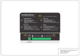
6. Place the Sub-base against the wall in the desired
location and mark the wall through the mounting
holes. If you are using a wired Internet connection, be
sure to mark the cutout for the RJ-45 connector (see
Figure 2 on page 5).
7. Drill the holes in the wall where marked.
If you are using a wireless Internet connection, skip to
step 9.
8. When using a wired Ethernet connection, follow these
step and refer to Figure 3 on page 5.
a. With the Sub-base and RJ-45 holder oriented as
shown, press the holder into the Sub-base.
b. Slide the holder to the right so it snaps in place.
c. Secure the holder with the provided screw.
d. Insert the RJ-45 Connector into the RJ-45
holder until it snaps into place.
9. Mount the Sub-base to the wall using included
mounting screws and drywall anchors. An optional
mounting hole is available for more secure mounting,
if needed. Make sure all wires extend through the hole
in the Sub-base see Figure 4 on page 5.
4.4 Wiring
1. Adjust the length and position of each wire to reach
the proper terminal on the connector block of the
Sub-base. Strip 1/4” of insulation from each wire.
Do not allow adjacent wires to short together when
connected.
2. Match and connect control wires to the proper
terminals on the connector block. Refer to Field Wiring
Diagrams included in this document.
3. Push excess wire back into the wall and seal the
hole to prevent air leaks. NOTE: Air Leaks in the wall
behind the Control can cause improper operation.
4. Attach the Control to the Sub-base.
5. Turn ON power to the heating and cooling equipment.
RS1 RS1 ODT ODT W3 W2 W1 BK G Y2 Y1 O B/C RH RC AUX2 AUX2 AUX1 AUX1
Mounting Holes
Optional Mounting Hole
Wall
Thermostat Wiring
Ethernet
Wiring
Thermostat
Wires
RJ-45
Plug
RS1 RS1 ODT ODT W3 W2 W1 BK G Y2 Y1 O B/C RH RC AUX2 AUX2 AUX1 AUX1
Mounting Holes
Optional Mounting Hole
Wall
Thermostat Wiring
Ethernet
Wiring
Thermostat
Wires
RJ-45
Plug
FIGURE 2. MARK THE MOUNTING HOLES
FIGURE 3. ATTACH RJ-45 HOLDER TO SUB-BASE
This side mounts to wall
Wall
a
b
c
d
FIGURE 4. MOUNT THE SUB-BASE TO THE WALL

Installation Guide
6 18-HD72D1-6
Field Wiring Connection Diagrams
Heat Pump Diagrams
Dual Fuel Diagrams
Heat/Cool Diagrams
PAGE DIAGRAM DESCRIPTION
7 DIAGRAM 1 1 OR 2 STAGE COOLING W/TAM7 MODEL VARIABLE SPEED AIR HANDLER
7 DIAGRAM 2 1 STAGE COOLING W/GAM5A OR TAM4 MODEL AIR HANDLER
8 DIAGRAM 3 1 STAGE COOLING W/GAM5B MODEL AIR HANDLER
8 DIAGRAM 4 2 STAGE COOLING W/GAM5B MODEL AIR HANDLER
9 DIAGRAM 5 1 STAGE COOLING W/GAF2-S MODEL AIR HANDLER
9 DIAGRAM 6 1 STAGE COOLING W/GAF2-36M MODEL AIR HANDLER
10 DIAGRAM 7 1 STAGE COOLING W/GAT2 & GAM2 MODEL AIR HANDLER
10 DIAGRAM 8 1 STAGE COOLING W/TEM3 MODEL AIR HANDLER
11 DIAGRAM 9 1 STAGE COOLING W/TEM4 AIR HANDLER
11 DIAGRAM 10 1 OR 2 STAGE COOLING W/TEM6 AIR HANDLER
12 DIAGRAM 11 1 STAGE W/COOLING GAS FURNACE
12 DIAGRAM 12 1 OR 2 STAGE COOLING W/VARIABLE SPEED GAS FURNACE
13 DIAGRAM 13 1 OR 2 STAGE COOLING WITH S9V2 FURNACE
13 DIAGRAM 14 PACKAGE 1 OR 2 STAGE HEAT/COOL W/VARIABLE SPEED BLOWER
14 DIAGRAM 15 PACKAGE 1 STAGE HEAT/COOL W/NON-VARIABLE SPEED BLOWER
14 DIAGRAM 16 AMERISTAR 1 STAGE COOLING
PAGE DIAGRAM DESCRIPTION
16 DIAGRAM 17 1 OR 2 STAGE HEAT PUMP W/TAM7 MODEL AIR HANDLER
16 DIAGRAM 18 1 STAGE HEAT PUMP W/GAM5A OR TAM4 MODEL AIR HANDLER
17 DIAGRAM 19 1 STAGE HEAT PUMP W/GAM5B MODEL AIR HANDLER
17 DIAGRAM 20 2 STAGE HEAT PUMP W/GAM5B MODEL AIR HANDLER
18 DIAGRAM 21 1 STAGE HEAT PUMP W/GAF2-S MODEL AIR HANDLER
18 DIAGRAM 22 1 STAGE HEAT PUMP W/GAF2-36M MODEL AIR HANDLER
19 DIAGRAM 23 1 STAGE HEAT PUMP W/GAT2 & GAM2 MODEL AIR HANDLER
19 DIAGRAM 24 1 STAGE HEAT PUMP W/TEM3 MODEL AIR HANDLER
20 DIAGRAM 25 1 STAGE HEAT PUMP W/TEM4 AIR HANDLER
20 DIAGRAM 26 1 OR 2 STAGE HEAT PUMP W/TEM6 VARIABLE SPEED AIR HANDLER
21 DIAGRAM 27 PACKAGE 1 OR 2 STAGE HEAT PUMP W/VARIABLE SPEED BLOWER
21 DIAGRAM 28 PACKAGE 1 STAGE HEAT PUMP W/NON-VARIABLE SPEED BLOWER
22 DIAGRAM 29 AMERISTAR 1 STAGE HEAT PUMP
PAGE DIAGRAM DESCRIPTION
23 DIAGRAM 30 1 OR 2 STAGE HEAT PUMP W/VARIABLE SPEED GAS FURNACE
23 DIAGRAM 31 1 STAGE HEAT PUMP W/NON-VARIABLE SPEED GAS FURNACE
24 DIAGRAM 32 1 OR 2 STAGE HEAT PUMP W/S9V2 FURNACE
24 DIAGRAM 33 PACKAGE 1 OR 2 STAGE DUAL FUEL W/VARIABLE SPEED BLOWER

824 Programmable Wi-Fi Comfort Control
18-HD72D1-6 7
4.5 Heat/Cool Applications
Diagram 1 - 1 or 2 Stage Cooling w/TAM7 Model Variable Speed Air Handler
Diagram 2 - 1 Stage Cooling w/GAM5A or TAM4 Model Air Handler
AUX 1
AUX 2
24VAC HOT
COMMON
SOV
COOLING
FA N
HEATING
ODT
RS
AUX1
AUX1
AUX2
AUX2
RC
RH
B/C
O
Y1
Y2
G
BK
W1
W2
W3
ODT
ODT
RS1
RS1
O
R
B
YI
YO
W3
Y2
G
BK
W1
W2
R
B
Y/Y1
Y2
Optional
Outdoor
Sensor*
Optional
Remote
Sensor*
3
2
1
4
4
824 COMFORT CONTROL
1- 1 OR 2 STAGE COOLING W/TAM7 MODEL VARIABLE SPEED AIR HANDLER
INDOOR UNIT
OUTDOOR UNIT
NOTES:
1. Cut and remove the BK jumper at the indoor unit
AFC Board
2. YI and YO connections must be made as shown
for freeze protection and internally mounted
condensate overflow circuits to function properly
3. If a 3rd party overflow condensate switches are
installed, wire between Y1 of the 824 and YI of the
airflow control board
4. R and Y2 connections at outdoor unit are required
only for two stage units
*Caution: Do not run Outdoor/Remote
sensor wires in the same bundle
with HVAC wires. Also, keep away
from high voltage wiring to avoid
interference.
AUX 1
AUX 2
24VAC HOT
COMMON
SOV
COOLING
FA N
HEATING
ODT
RS
AUX1
AUX1
AUX2
AUX2
RC
RH
B/C
O
Y1
Y2
G
BK
W1
W2
W3
ODT
ODT
RS1
RS1
O
R
B
YI
YO
W3
G
W1
W2
B
Y
Optional
Outdoor
Sensor*
Optional
Remote
Sensor*
2
1
*Caution: Do not run Outdoor/Remote
sensor wires in the same bundle
with HVAC wires. Also, keep away
from high voltage wiring to avoid
interference.
2- 1 STAGE COOLING W/GAM5A OR TAM4 MODEL AIR HANDLER
824 COMFORT CONTROL
INDOOR UNIT
OUTDOOR UNIT
NOTES:
1. YI and YO connections must be made as shown for
freeze protection and internally mounted condensate
overflow circuits to function properly
2. If 3rd party overflow condensate switches are
installed, wire between Y1 of the 824 and YI of the
air handler

Installation Guide
8 18-HD72D1-6
Diagram 4 - 2 Stage Cooling w/GAM5B Model Air Handler
Diagram 3 - 1 Stage Cooling w/GAM5B Model Air Handler
AUX 1
AUX 2
24VAC HOT
COMMON
SOV
COOLING
FA N
HEATING
ODT
RS
AUX1
AUX1
AUX2
AUX2
RC
RH
B/C
O
Y1
Y2
G
BK
W1
W2
W3
ODT
ODT
RS1
RS1
O
R
B
Y
W3
G
W1
W2
B
Y
Optional
Outdoor
Sensor*
Optional
Remote
Sensor*
1
*Caution: Do not run Outdoor/Remote
sensor wires in the same bundle
with HVAC wires. Also, keep away
from high voltage wiring to avoid
interference.
3- 1 STAGE COOLING W/GAM5B MODEL AIR HANDLER
824 COMFORT CONTROL
INDOOR UNIT
OUTDOOR UNIT
NOTES:
1. Y terminal must be connected at indoor unit for
selected compressor air flow
AUX 1
AUX 2
24VAC HOT
COMMON
SOV
COOLING
FA N
HEATING
ODT
RS
AUX1
AUX1
AUX2
AUX2
RC
RH
B/C
O
Y1
Y2
G
BK
W1
W2
W3
ODT
ODT
RS1
RS1
Y
R
B
W3
G
W1
W2
R
B
Y1
Y2
Optional
Outdoor
Sensor*
Optional
Remote
Sensor*
1
*Caution: Do not run Outdoor/Remote
sensor wires in the same bundle
with HVAC wires. Also, keep away
from high voltage wiring to avoid
interference.
824 COMFORT CONTROL
4- 2 STAGE COOLING W/GAM5B MODEL AIR HANDLER
INDOOR UNIT OUTDOOR UNIT
NOTES:
1. Y terminal must be connected at indoor unit for
selected compressor air flow

824 Programmable Wi-Fi Comfort Control
18-HD72D1-6 9
Diagram 5 - 1 Stage Cooling w/GAF2-S Model Air Handler
Diagram 6 - 1 Stage Cooling w/GAF2-36M Model Air Handler
AUX 1
AUX 2
24VAC HOT
COMMON
SOV
COOLING
FA N
HEATING
ODT
RS
AUX1
AUX1
AUX2
AUX2
RC
RH
B/C
O
Y1
Y2
G
BK
W1
W2
W3
ODT
ODT
RS1
RS1
R
B
G
W
B
Y
Optional
Outdoor
Sensor*
Optional
Remote
Sensor*
*Caution: Do not run Outdoor/Remote
sensor wires in the same bundle
with HVAC wires. Also, keep away
from high voltage wiring to avoid
interference.
824 COMFORT CONTROL
5- 1 STAGE COOLING W/GAF2-S MODEL AIR HANDLER
INDOOR UNIT
OUTDOOR UNIT
AUX 1
AUX 2
24VAC HOT
COMMON
SOV
COOLING
FA N
HEATING
ODT
RS
AUX1
AUX1
AUX2
AUX2
RC
RH
B/C
O
Y1
Y2
YI
YO
G
BK
W1
W2
W3
ODT
ODT
RS1
RS1
R
B
O
G
W
B
Y
Optional
Outdoor
Sensor*
Optional
Remote
Sensor*
1
3
2
*Caution: Do not run Outdoor/Remote
sensor wires in the same bundle
with HVAC wires. Also, keep away
from high voltage wiring to avoid
interference.
NOTES:
1. YI and YO connections must be made as shown for
freeze protection and internally mounted condensate
overflow circuits to function properly
2. If 3rd party overflow condensate switches are
installed, wire between Y1 of the 824 and YI of the
air handler
3. Jumper R and O must be installed for blower to run
at cooling airflow
824 COMFORT CONTROL
6- 1 STAGE COOLING W/GAF2-36M MODEL AIR HANDLER
INDOOR UNIT
OUTDOOR UNIT

Installation Guide
10 18-HD72D1-6
Diagram 8 - 1 Stage Cooling w/TEM3 Model Air Handler
Diagram 7 - 1 Stage Cooling w/GAT2 & GAM2 Model Air Handler
AUX 1
AUX 2
24VAC HOT
COMMON
SOV
COOLING
FA N
HEATING
ODT
RS
AUX1
AUX1
AUX2
AUX2
RC
RH
B/C
O
Y1
Y2
G
BK
W1
W2
W3
W2
W3
ODT
ODT
RS1
RS1
R
B
G
W1
B
Y
Optional
Outdoor
Sensor*
Optional
Remote
Sensor*
*Caution: Do not run Outdoor/Remote
sensor wires in the same bundle
with HVAC wires. Also, keep away
from high voltage wiring to avoid
interference.
824 COMFORT CONTROL
7- 1 STAGE COOLING W/GAT2 & GAM2 MODEL AIR HANDLER
INDOOR UNIT
OUTDOOR UNIT
AUX 1
AUX 2
24VAC HOT
COMMON
SOV
COOLING
FA N
HEATING
ODT
RS
AUX1
AUX1
AUX2
AUX2
RC
RH
B/C
O
Y1
Y2
G
BK
W1
W2
W3
ODT
ODT
RS1
RS1
R
B
G
W1
W2
B
Y
Optional
Outdoor
Sensor*
Optional
Remote
Sensor*
*Caution: Do not run Outdoor/Remote
sensor wires in the same bundle
with HVAC wires. Also, keep away
from high voltage wiring to avoid
interference.
824 COMFORT CONTROL
8- 1 STAGE COOLING W/TEM3 MODEL AIR HANDLER
INDOOR UNIT
OUTDOOR UNIT

824 Programmable Wi-Fi Comfort Control
18-HD72D1-6 11
Diagram 9 - 1 Stage Cooling w/TEM4 Air Handler
9-1 STAGE COOLING W/TEM4
AUX 1
AUX 2
24VAC HOT
COMMON
SOV
COOLING
FA N
HEATING
ODT
RS
AUX1
AUX1
AUX2
AUX2
RC
RH
B/C
O
Y1
Y2
G
BK
W1
W2
W3
ODT
ODT
RS1
RS1
R
B B
G
W1
W2
Y
Optional
Outdoor
Sensor*
Optional
Remote
Sensor*
*Caution: Do not run Outdoor/Remote
sensor wires in the same bundle
with HVAC wires. Also, keep away
from high voltage wiring to avoid
interference.
824 COMFORT CONTROL
INDOOR UNIT
OUTDOOR UNIT
Diagram 10 - 1 or 2 Stage Cooling w/TEM6 Air Handler
NOTES:
1. Cut and remove the BK jumper at the indoor unit
2. R & Y2 connections at outdoor are only required for
two stage units
AUX 1
AUX 2
24VAC HOT
COMMON
SOV
COOLING
FA N
HEATING
ODT
RS
AUX1
AUX1
AUX2
AUX2
RC
RH
B/C
O
Y1
Y2
Y1
Y2
G
BK
W1
W2
W3
ODT
ODT
RS1
RS1
R R
B
W3
BK
G
W1
W2
B
Y1
Y2
Optional
Outdoor
Sensor*
Optional
Remote
Sensor*
*Caution: Do not run Outdoor/Remote
sensor wires in the same bundle
with HVAC wires. Also, keep away
from high voltage wiring to avoid
interference.
824 COMFORT CONTROL
INDOOR UNIT OUTDOOR UNIT
10-1 OR 2 STAGE COOLING W/TEM6
2
1
2

Installation Guide
12 18-HD72D1-6
Diagram 12 - 1 or 2 Stage Cooling w/Variable Speed Gas Furnace
AUX 1
AUX 2
24VAC HOT
COMMON
SOV
COOLING
FA N
HEATING
ODT
RS
AUX1
AUX1
AUX2
AUX2
RC
RH
B/C
O O
Y1
Y2Y2
Y1/Ylo
Y/Y2
G
BK
BK
W1
W2
W3
ODT
ODT
RS1
RS1
R R
B
G
W1
W2
B
Y/Y1
Optional
Outdoor
Sensor*
Optional
Remote
Sensor*
*Caution: Do not run Outdoor/Remote
sensor wires in the same bundle
with HVAC wires. Also, keep away
from high voltage wiring to avoid
interference.
NOTES:
1. Cut and remove the factory installed BK jumper at
the indoor unit IFC Board (some units may require
DIP switch settings)
2. R & Y2 connections at outdoor are only required for
two stage units
824 COMFORT CONTROL
12- 1 OR 2 STAGE COOLING W/VARIABLE SPEED GAS FURNACE
INDOOR UNIT OUTDOOR UNIT
2
1
2
Diagram 11 - 1 Stage w/Cooling Gas Furnace
AUX 1
AUX 2
24VAC HOT
COMMON
SOV
COOLING
FA N
HEATING
ODT
RS
AUX1
AUX1
AUX2
AUX2
RC
RH
B/C
O
Y1 Y
Y2
G
BK
W1
W2
W3
ODT
ODT
RS1
RS1
R
B
W3
G
W1
W2
B
Y
Optional
Outdoor
Sensor*
Optional
Remote
Sensor*
*Caution: Do not run Outdoor/Remote
sensor wires in the same bundle
with HVAC wires. Also, keep away
from high voltage wiring to avoid
interference.
824 COMFORT CONTROL
11- 1 STAGE COOLING W/GAS FURNACE
INDOOR UNIT
OUTDOOR UNIT

824 Programmable Wi-Fi Comfort Control
18-HD72D1-6 13
Diagram 13 - 1 or 2 Stage Cooling with S9V2 Furnace
Diagram 14 - Package 1 or 2 Stage Heat/Cool w/Variable Speed Blower
AUX 1
AUX 2
24VAC HOT
COMMON
SOV
COOLING
FA N
HEATING
ODT
RS
AUX1
AUX1
AUX2
AUX2
RC
RH
B/C
O
Y1 Y/Y1
Y2Y2
G
BK
W1
W2
W3
ODT
ODT
RS1
RS1
R
B
BK
G
W1
W2/X2
Optional
Outdoor
Sensor*
Optional
Remote
Sensor*
*Caution: Do not run Outdoor/Remote
sensor wires in the same bundle
with HVAC wires. Also, keep away
from high voltage wiring to avoid
interference.
NOTES:
1. Remove “R” to “BK” jumper and clip all “Y”
connections at the integrated motor control board
(ICMC) to enable pulse width control of the variable
speed indoor blower. Ensure clipped wires are
capped and taped off.
824 COMFORT CONTROL
14- PACKAGE 1 OR 2 STAGE HEAT/COOL w/VARIABLE SPEED BLOWER
PACKAGE UNIT
1
13-1 OR 2 STAGE COOLING w/S9V2 FURNACE
NOTES:
1. Cut and remove the BK jumper at the indoor unit
2. Remove the factory Y1-O jumper on the indoor unit
for heat pump systems for proper LED readout
3. Y1 and Y2 wiring from the 824 must connect to Y1
and Y2 of the indoor unit IFC for proper air flow and
LED read out
4. R connection at outdoor unit is required only for two
compressor/two stage units
AUX 1
AUX 2
24VAC HOT
COMMON
SOV
COOLING
FA N
HEATING
ODT
RS
AUX1
AUX1
AUX2
AUX2
RC
RH
B/C
O
Y1
Y2
Y1/Ylo
Y/Y2
G
BK
W1
W2
W3
ODT
ODT
RS1
RS1
R R
B/C
O
BK
G
W1
W2
B
Y1
Y2
Optional
Outdoor
Sensor*
Optional
Remote
Sensor*
*Caution: Do not run Outdoor/Remote
sensor wires in the same bundle
with HVAC wires. Also, keep away
from high voltage wiring to avoid
interference.
824 COMFORT CONTROL
INDOOR UNIT OUTDOOR UNIT
2
4
1
3
3

Installation Guide
14 18-HD72D1-6
Diagram 15 - Package 1 Stage Heat/Cool w/Non-Variable Speed Blower
Diagram 16 - Ameristar 1 Stage Cooling
AUX 1
AUX 2
24VAC HOT
COMMON
SOV
COOLING
FA N
HEATING
ODT
RS
AUX1
AUX1
AUX2
AUX2
RC
RH
B/C
O
Y1 Y
Y2
G
BK
W1
W2
W3
ODT
ODT
RS1
RS1
R
B
G
W1
W2
Optional
Outdoor
Sensor*
Optional
Remote
Sensor*
*Caution: Do not run Outdoor/Remote
sensor wires in the same bundle
with HVAC wires. Also, keep away
from high voltage wiring to avoid
interference.
824 COMFORT CONTROL
15- PACKAGE 1 STAGE HEAT/COOL W/NON-VARIABLE SPEED BLOWER
PACKAGE UNIT
AUX 1
AUX 2
24VAC HOT
COMMON
SOV
COOLING
FA N
HEATING
ODT
RS
AUX1
AUX1
AUX2
AUX2
RC
RH
B/C
O
Y1
Y2
G
BK
W1
W2
W1
W2
W3
ODT
ODT
RS1
RS1
R
C
G
C
Y
Optional
Outdoor
Sensor*
Optional
Remote
Sensor*
*Caution: Do not run Outdoor/Remote
sensor wires in the same bundle
with HVAC wires. Also, keep away
from high voltage wiring to avoid
interference.
NOTES:
1. B/C at the Control is 24v common and must be
connected to C at the Indoor and Outdoor Units
824 COMFORT CONTROL
INDOOR
UNIT
AIR
CONDITIONER
16- AMERISTAR 1 STAGE COOLING
1

824 Programmable Wi-Fi Comfort Control
18-HD72D1-6 15

Installation Guide
16 18-HD72D1-6
Diagram 18 - 1 Stage Heat Pump w/GAM5A or TAM4 Model Air Handler
Diagram 17 - 1 or 2 Stage Heat Pump w/TAM7 Model Air Handler
4.6 Heat Pump Applications
AUX 1
AUX 2
24VAC HOT
COMMON
SOV
COOLING
FA N
HEATING
ODT
RS
AUX1
AUX1
AUX2
AUX2
RC
RH
B/C
O
Y1
Y2
YI
YO
G
BK
W1
W2
Y2 Y2
G
BK
W1
W3 W2
ODT W3
ODT
RS1
RS1
O
Y1
O
R
B
R
X2
B
Optional
Outdoor
Sensor*
Optional
Remote
Sensor*
3 2
4
2
1
824 COMFORT CONTROL
17- 1 OR 2 STAGE HEAT PUMP W/TAM7 MODEL AIR HANDLER
INDOOR UNIT OUTDOOR UNIT
NOTES:
1. Remove the factory installed BK jumper at the
indoor unit’s AFC Board
2. YI and YO connections must be made as shown
for freeze protection and internally mounted
condensate overflow circuits to function properly
3. Wire 3rd party condensate overflow switches
between Y1 of the 824 and YI of the airflow control
board
4. Connection to X2 is not required for this
configuration
*Caution: Do not run Outdoor/Remote
sensor wires in the same bundle
with HVAC wires. Also, keep away
from high voltage wiring to avoid
interference.
X2
AUX 1
AUX 2
24VAC HOT
COMMON
SOV
COOLING
FA N
HEATING
ODT
RS
AUX1
AUX1
AUX2
AUX2
RC
RH
B/C
O
Y1
Y2
YI
YO
G
BK
W1
W2
G
W1
W3 W2
ODT W3
ODT
RS1
RS1
O
Y
O
R
B
R
B
Optional
Outdoor
Sensor*
Optional
Remote
Sensor*
3
2
1
1
18- 1 STAGE HEAT PUMP W/GAM5A MODEL AIR HANDLER
824 COMFORT CONTROL
INDOOR UNIT OUTDOOR UNIT
NOTES:
1.
YI and YO connections must be made as shown
for freeze protection and internally mounted
condensate overflow circuits to function properly
2. Wire 3rd party condensate overflow switches
beteeen Y1 of the 824 and Y of the air handler
3. Connection to X2 is not required for this
configuration
*Caution: Do not run Outdoor/Remote
sensor wires in the same bundle
with HVAC wires. Also, keep away
from high voltage wiring to avoid
interference.

824 Programmable Wi-Fi Comfort Control
18-HD72D1-6 17
Diagram 20 - 2 Stage Heat Pump w/GAM5B Model Air Handler
Diagram 19 - 1 Stage Heat Pump w/GAM5B Model Air Handler
X2
AUX 1
AUX 2
24VAC HOT
COMMON
SOV
COOLING
FA N
HEATING
ODT
RS
AUX1
AUX1
AUX2
AUX2
RC
RH
B/C
O
Y1
Y2
Y
G
BK
W1
W2
G
W1
W3
W2
ODT
W3
ODT
RS1
RS1
Y
O
R
B
R
B
Optional
Outdoor
Sensor*
Optional
Remote
Sensor*
2
1
19- 1 STAGE HEAT PUMP W/GAM5B MODEL AIR HANDLER
824 COMFORT CONTROL
INDOOR UNIT OUTDOOR UNIT
NOTES:
1. Y terminal must be connected at indoor unit for
selected compressor air flow
2. Connection to X2 is not required for this
configuration
*Caution: Do not run Outdoor/Remote
sensor wires in the same bundle
with HVAC wires. Also, keep away
from high voltage wiring to avoid
interference.
1
X2
AUX 1
AUX 2
24VAC HOT
COMMON
SOV
COOLING
FA N
HEATING
ODT
RS
AUX1
AUX1
AUX2
AUX2
RC
RH
B/C
O
Y1
Y2
Y
G
BK
W1
W2
Y2
G
W1
W3
W2
ODT
W3
ODT
RS1
RS1
Y1
O
R
B
R
B
Optional
Outdoor
Sensor*
Optional
Remote
Sensor*
2
20- 2 STAGE HEAT PUMP W/GAM5B MODEL AIR HANDLER
824 COMFORT CONTROL
INDOOR UNIT OUTDOOR UNIT
NOTES:
1. Y terminal must be connected at indoor unit for
selected compressor air flow
2. Connection to X2 is not required for this
configuration
*Caution: Do not run Outdoor/Remote
sensor wires in the same bundle
with HVAC wires. Also, keep away
from high voltage wiring to avoid
interference.

Installation Guide
18 18-HD72D1-6
Diagram 22 - 1 Stage Heat Pump w/GAF2-36M Model Air Handler
Diagram 21 - 1 Stage Heat Pump w/GAF2-S Model Air Handler
X2
AUX 1
AUX 2
24VAC HOT
COMMON
SOV
COOLING
FA N
HEATING
ODT
RS
AUX1
AUX1
AUX2
AUX2
RC
RH
B/C
O
Y1
Y2
G
BK
W1
W2
G
W
W3
ODT
ODT
RS1
RS1
Y
O
R
B
R
B
Optional
Outdoor
Sensor*
Optional
Remote
Sensor*
1
21- 1 STAGE HEAT PUMP W/GAF2-S MODEL AIR HANDLER
824 COMFORT CONTROL
INDOOR UNIT OUTDOOR UNIT
NOTES:
1. Connection to X2 is not required for this
configuration
*Caution: Do not run Outdoor/Remote
sensor wires in the same bundle
with HVAC wires. Also, keep away
from high voltage wiring to avoid
interference.
X2
AUX 1
AUX 2
24VAC HOT
COMMON
SOV
COOLING
FA N
HEATING
ODT
RS
AUX1
AUX1
AUX2
AUX2
RC
RH
B/C
O
Y1
Y2
O
YI
YO Y
G
BK
W1
W2
G
W
W3
ODT
ODT
RS1
RS1
O
R
B
R
B
Optional
Outdoor
Sensor*
Optional
Remote
Sensor*
3
22- 1 STAGE HEAT PUMP W/GAF2-36M MODEL AIR HANDLER
824 COMFORT CONTROL
INDOOR UNIT OUTDOOR UNIT
NOTES:
1. YI and YO connections must be made as shown
for freeze protection and internally mounted
condensate overflow circuits to function properly
2. Wire 3rd party condensate overflow switches
beteeen Y1 of the 824 and YI of the air handler
3. Connection to X2 is not required for this
configuration
2 1
1
*Caution: Do not run Outdoor/Remote
sensor wires in the same bundle
with HVAC wires. Also, keep away
from high voltage wiring to avoid
interference.

824 Programmable Wi-Fi Comfort Control
18-HD72D1-6 19
Diagram 24 - 1 Stage Heat Pump w/TEM3 Model Air Handler
Diagram 23 - 1 Stage Heat Pump w/GAT2 & GAM2 Model Air Handler
X2
AUX 1
AUX 2
24VAC HOT
COMMON
SOV
COOLING
FA N
HEATING
ODT
RS
AUX1
AUX1
AUX2
AUX2
RC
RH
B/C
O
Y1
Y2
Y
G
BK
W1
W2
G
W1
W3
W2
W3
ODT
ODT
RS1
RS1
O
R
B
R
B
Optional
Outdoor
Sensor*
Optional
Remote
Sensor*
1
23- 1 STAGE HEAT PUMP W/GAT2 & GAM2 MODEL AIR HANDLER
824 COMFORT CONTROL
INDOOR UNIT OUTDOOR UNIT
NOTES:
1. Connection to X2 is not required for this
configuration
*Caution: Do not run Outdoor/Remote
sensor wires in the same bundle
with HVAC wires. Also, keep away
from high voltage wiring to avoid
interference.
X2
AUX 1
AUX 2
24VAC HOT
COMMON
SOV
COOLING
FA N
HEATING
ODT
RS
AUX1
AUX1
AUX2
AUX2
RC
RH
B/C
O
Y1
Y2
Y
G
BK
W1
W2
G
W1
W3
W2
ODT
ODT
RS1
RS1
O
R
B
R
B
Optional
Outdoor
Sensor*
Optional
Remote
Sensor*
1
24- 1 STAGE HEAT PUMP W/TEM3 MODEL AIR HANDLER
824 COMFORT CONTROL
INDOOR UNIT OUTDOOR UNIT
NOTES:
1. Connection to X2 is not required for this
configuration
*Caution: Do not run Outdoor/Remote
sensor wires in the same bundle
with HVAC wires. Also, keep away
from high voltage wiring to avoid
interference.

Installation Guide
20 18-HD72D1-6
Diagram 25 - 1 Stage Heat Pump w/TEM4 Air Handler
Diagram 26 - 1 or 2 Stage Heat Pump w/TEM6 Variable Speed Air Handler
X2
AUX 1
AUX 2
24VAC HOT
COMMON
SOV
COOLING
FA N
HEATING
ODT
RS
AUX1
AUX1
AUX2
AUX2
RC
RH
B/C
O
Y1
Y2
Y
G
BK
W1
W2
G
W1
W3
W2
W3
ODT
ODT
RS1
RS1
O
R
B
R
B
Optional
Outdoor
Sensor*
Optional
Remote
Sensor*
1
25- 1 STAGE HEAT PUMP W/TEM4 MODEL AIR HANDLER
824 COMFORT CONTROL
INDOOR UNIT OUTDOOR UNIT
NOTES:
1. Connection to X2 is not required for this
configuration
*Caution: Do not run Outdoor/Remote
sensor wires in the same bundle
with HVAC wires. Also, keep away
from high voltage wiring to avoid
interference.
X2
AUX 1
AUX 2
24VAC HOT
COMMON
SOV
COOLING
FA N
HEATING
ODT
RS
AUX1
AUX1
AUX2
AUX2
R
RH
B/C
O
Y1
Y2
Y2
G
BK
W1
W2
Y2
G
BK
W1
W3
W2
ODT
ODT
RS1
RS1
Y1
O
R
B
O
Y1
R
B
Optional
Outdoor
Sensor*
Optional
Remote
Sensor*
2
1
26- 1 OR 2 STAGE HEAT PUMP W/TEM6 MODEL VARIABLE SPEED AIR HANDLER
824 COMFORT CONTROL
INDOOR UNIT OUTDOOR UNIT
NOTES:
1. Remove the factory installed BK jumper at the
indoor unit
2. Connection to X2 is not required for this
configuration
3. R & Y2 connections at outdoor are only required for
two stage units
*Caution: Do not run Outdoor/Remote
sensor wires in the same bundle
with HVAC wires. Also, keep away
from high voltage wiring to avoid
interference.
/