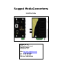
RuggedCom MEDIACONVERTER Installation guide
- Category
- Network switches
- Type
- Installation guide
This manual is also suitable for


2
RuggedCom
®
RuggedMC™
RMC Installation Guide rev105
Copyright
COPYRIGHT © 2010 RuggedCom Inc. ALL RIGHTS RESERVED
Dissemination or reproduction of this document, or evaluation and communication of its contents, is
not authorized except where expressly permitted. Violations are liable for damages. All rights
reserved, particularly for the purposes of patent application or trademark registration.
This document contains proprietary information, which is protected by copyright. All rights are
reserved. No part of this document may be photocopied, reproduced or translated to another
language without the prior written consent of RuggedCom Inc.
Disclaimer of liability
We have checked the contents of this manual against the hardware and software described.
However, deviations from the description cannot be completely ruled out.
RuggedCom shall not be liable for any errors or omissions contained herein or for consequential
damages in connection with the furnishing, performance, or use of this material.
The information given in this document is reviewed regularly and any necessary corrections will be
included in subsequent editions. We appreciate any suggested improvements. We reserve the right
to make technical improvements without notice.
Registered Trademarks
Rugged MediaConverter™, ROS™ and RuggedMC™ are trademarks of RuggedCom Inc. Other
designations in this manual might be trademarks whose use by third parties for their own purposes
would infringe the rights of the owner.
Important:
The Rugged MediaConverter
TM
(RuggedMC
TM
) contains no user-serviceable parts. Attempted
service by unauthorized personnel shall render all warranties null and void.
Warning: Changes or modifications not expressly approved by RuggedCom Inc. could void the
user’s authority to operate the equipment.
The RuggedMC
TM
should be installed in a restricted access location where access can only be
gained by service personnel or users who have been instructed about the reasons for the
restrictions applied to the location and about any precautions that shall be taken; and access is
through the use of a tool or lock and key, or other means of security, and is controlled by the
authority responsible for the location.

Contacting RuggedCom
Corporate Headquarters US Headquarters Europe Headquarters
RuggedCom Inc.
300 Applewood Crescent
Concord, Ontario
Canada, L4K 5C7
Tel: +1 905 856 5288
Fax: +1 905 856 1995
Toll-free: 1 888 264 0006
RuggedCom
1930 Harrison St., Suite 209
Hollywood, Florida
USA, 33020
Tel: +1 954 922 7938 ext. 103
Fax: +1 954 922 7984
Toll-free: 1 888 264 0006
RuggedCom
Unit 41, Aztec Centre,
Aztec West, Almondsbury, Bristol
United Kingdom BS32 4TD
Tel: +44 1454 203 404
Fax: +44 1454 203 403
Technical Support
Toll Free (North America): 1 866 922 7975
International: +1 905 856 5288
Web: www.RuggedCom.com
3
Rug
ged
Com
®
RuggedMC™
RMC Installation Guide rev105

Table of Contents
Table of Contents
1 Product Overview.................................................................................................................... 5
1.1 Functional Overview....................................................................................................... 5
1.2 Feature Highlights........................................................................................................... 5
1.3 RuggedMC
TM
Front Panel Description............................................................................ 6
1.4 RuggedMC
TM
Side and Bottom View.............................................................................. 7
2 Installation............................................................................................................................... 8
2.1 DIN Rail Mounting........................................................................................................... 8
2.2 Power Supply Wiring and Grounding.............................................................................. 9
2.3 RJ45 Ports – Signal Description....................................................................................10
2.4 Fiber Optical Port Configuration.....................................................................................12
3 Technical Specifications.........................................................................................................14
3.1 Power Supply Specifications..........................................................................................14
3.2 Networking Standards Supported..................................................................................14
3.3 Copper Port Specifications............................................................................................15
3.4 Fiber Optical Specifications...........................................................................................15
3.5 Networking Specifications..............................................................................................15
3.6 Operating Environment..................................................................................................15
3.7 Physical Dimensions......................................................................................................16
4 Type Tests..............................................................................................................................17
4.1 IEC 61850-3 Type Tests................................................................................................17
4.2 IEEE 1613 Type Tests...................................................................................................18
4.3 IEC Environmental Type Tests......................................................................................18
5 Agency Approvals ..................................................................................................................19
6 Warranty.................................................................................................................................19
4
Rug
ged
Com
®
RuggedMC™
RMC Installation Guide rev105

Product Overview
1 Product Overview
1.1 Functional Overview
The Rugged MediaConverter
TM
is an industrially hardened fiber optical media converter
specifically designed to operate in harsh environments such as those found in electric utility
substations and factory floors. The RuggedMC
TM
family provides industrial strength Ethernet
copper-to-fiber media conversion, allowing for 10BaseT-to-10BaseFL or 100BaseTX-100BaseFX
over multi-mode or optional single-mode fiber optical media.
Specifically tested to the same standards as mission critical protective relaying equipment (i.e.
ANSI/IEEE C37.90 and IEC 60255), and the newly issued IEC 61850-3 “Communications Systems
and Networks in Substations” standard, the RuggedMC
TM
is ideally suited for substation or
industrial environments. The reliability of the Rugged MediaConverter
TM
family exceeds that of
commercial media converters by having no rotating mechanical parts (i.e. no cooling fans), utilizing
high-temperature solid state components and incorporating the necessary transient and surge
suppression circuitry required for substation and harsh industrial environments.
1.2 Feature Highlights
Utility Grade (i.e. substation hardened) per ANSI/IEEE C37.90, IEC 60255, and the new IEC
61850-3 (2002), IEC 61000-6-5 standards
Operating temperature: -40 to 85C (no fan)
Radiated RF Immunity: 35V/m per ANSI/IEEE C37.90.2
Power supply options: 24 (18-36VDC), 48 (36-72) or HI (88-300VDC / 85-264VAC)
Choice of two fiber optical modules:
1 – 100BaseFX (100Mbps) multimode or optional single-mode fiber optical port
1 - 10BaseFL (10Mbps) multimode or optional single-mode fiber optical port
1 – 10/100BaseTX Auto-Negotiating RJ45 port
Configurable Full-Duplex, Half-Duplex or Fiber-side negotiation support
Link Pass Through support
TIA/EIA-785 100BaseSX support (10FL module only)
5
RuggedCom
®
RuggedMC™
RMC Installation Guide rev105

Product Overview
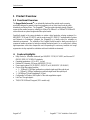
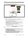
1.3 RuggedMC
TM
Front Panel Description
Figure 1: RuggedMC
TM
Front Panel Detail
ITEM Activity Comments
Copper Side: Link Solid (Yellow) Link Established
Copper Side: Activity Blinking (Yellow) Tx, Rx Activity
Fiber Side: Link Solid (Yellow) Link Established
Fiber Side: Activity Blinking (Yellow) Tx, Rx Activity
Power LED Solid (Green) Power On
6
RuggedCom
®
RuggedMC™
RMC Installation Guide rev105

Product Overview
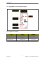
1.4 RuggedMC
TM
Side and Bottom View
Figure 2: RuggedMC
TM
Side and Bottom View
7
RuggedCom
®
RuggedMC™
RMC Installation Guide rev105

Installation
2 Installation
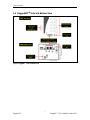
2.1 DIN Rail Mounting
Figure 3: RuggedMC
TM
DIN Rail Mounting
8
RuggedCom
®
RuggedMC™
RMC Installation Guide rev105

Installation
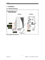
2.2 Power Supply Wiring and Grounding
Figure 4: RuggedMC
TM
Power Supply Inputs
The RuggedMC
TM
power supply inputs are identical and are connected as follows:
1. +/L = DC (+) / AC (Hot) is connected to the positive (+) terminal if the power source is DC
or to the (Hot) terminal if the power source is AC.
2. -/N = DC (-) / AC (Neutral) is connected to the negative (-) terminal if the power source is
DC or to the (Neutral) terminal if the power source is AC.
3. Surge Ground is connected to the Chassis Ground via a braided cable or other
appropriate grounding wire. Surge Ground is used as the ground conductor for all surge
and transient suppression circuitry internal to the RuggedMC
TM
.
Chassis Ground is connected to the Safety Ground terminal for AC inputs or the
equipment ground bus for DC inputs.
Note: Surge Ground must be disconnected from Chassis Ground during HIPOT
(dielectric strength) testing.
Notes:
1. For 125/250VDC rated equipment: An appropriately rated 300VDC circuit breaker
must be installed within 3 meters of unit.
2. For 110/230VAC rated equipment: An appropriately rated 250VAC circuit breaker
must be installed within 3 meters of the unit
3. A circuit breaker is not required for 48 or 24VDC rated equipment.
4. For multiple supplies, separate circuit breakers must be installed. Equipment must
be installed according to the applicable country wiring codes.
9
RuggedCom
®
RuggedMC™
RMC Installation Guide rev105

Installation
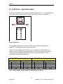
2.3 RJ45 Ports – Signal Description
The RJ45 port accepts standard category 5 unshielded twisted pair (UTP), or screened twisted pair
(STP) cable with RJ45 male connectors. Figure 5 shows the RJ45 port pin configuration.
PIN 1
PIN 8
PIN SIGNAL
1 RX+
2 RX-
3 TX+
4 n.c.
5 n.c.
6 TX-
7 n.c.
8 n.c.
PIN 1
PIN 8
PIN SIGNAL
1 RX+
2 RX-
3 TX+
4 n.c.
5 n.c.
6 TX-
7 n.c.
8 n.c.
Figure 5: RJ45 Port Pins
To accommodate signals from end devices as well as network switching equipment, the
RuggedMC
TM
is equipped with a crossover selection switch.
Category 5 network cabling can be constructed in two configurations: Straight through, and
crossover (X-over). Straight through cabling involves a pin-to-pin connection, while crossover
cabling matches the transmitting differential pair to the receiving differential pair. Table 1
summarizes the two possible configurations.
TIA 568B Straight Through Pinout TIA 568B Crossover Wiring Pinout
Device 1 Device 2 Device 1 Device 2
Pin Colour Pin Colour Pin Colour Pin Colour
1 White/Orange 1 White/Orange 1 White/Orange 1 White/Green
2 Orange 2 Orange 2 Orange 2 Green
3 White/Green 3 White/Green 3 White/Green 3 White/Orange
6 Green 6 Green 6 Green 6 Orange
Table 1 - Category 5 network cabling configurations: Straight through and Crossover
10
RuggedCom
®
RuggedMC™
RMC Installation Guide rev105

Installation
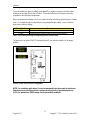
To accommodate both types of cabling, the RuggedMC
TM
contains a crossover selection switch
visible on the front panel as shown in Table 2. This switch will allow for the proper connection
regardless of the cable type configuration.
When connecting to end devices, the X-over switch should be selected to reflect the type of cabling
used. (i.e. Straight through is selected when using straight through cabling, X-over is selected
when using crossover cabling)
X-Over Position Description
UP Crossover cabling is used to connect to end devices.
DOWN Straight-through cabling is used to connect to end devices.
Table 2 - X-over switch positioning for Straight through and Crossover cabling
The presence of an active LINK LED indicates that the X-over selection switch is in the proper
position.
Figure 6: Location of X-over Switch on RuggedMC
TM
NOTE: For substation applications it is not recommended to use these ports to interface to
field devices across distances which could produce high levels of ground potential rise
(GPR), (i.e. greater than 2500V) during line-to-ground fault conditions.
11
RuggedCom
®
RuggedMC™
RMC Installation Guide rev105

Installation
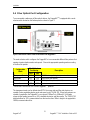
2.4 Fiber Optical Port Configuration
To accommodate a wide array of fiber optical devices, the RuggedMC
TM
is equipped with a mode
selector switch located on the bottom panel as shown in Figure 7.
Figure 7: Mode Selector Switch located on the bottom of the RuggedMC
TM
The mode selector switch configures the RuggedMC
TM
to accommodate different fiber partners that
operate at various duplex modes and speeds. Choose the appropriate operating mode according
to the fiber link partner.
Mode Selector
Positioning
Configuration
Mode
SW1 SW2
Description
Transparent Mode* OFF OFF 10/100 Auto-negotiating transparent mode
HDX Mode OFF ON Half-Duplex fiber partner
FDX Mode ON OFF Full-Duplex fiber partner (default)
Reserved ON ON
* Should ONLY be used on 10FL series RuggedMC
TM
products.
The transparent mode can be utilized when BOTH the copper side and fiber side devices are
capable of auto-negotiating duplex mode and speed as per TIA/EIA-785. When both partners are
capable of negotiation, the RuggedMC
TM
can support 100BaseTx to 100BaseSX, full duplex,
copper-to-fiber media conversion on 10FL standard electronics and fiber media. The TIA/EIA-785
standard allows for 10FL communication lines that are less than 300m in length to be upgraded to
100Mb/s communication links.
12
RuggedCom
®
RuggedMC™
RMC Installation Guide rev105

Installation
The HDX and FDX modes exist to accommodate fiber link partners that are operating in the forced
mode. Due to the high number of forced full duplex fiber optical devices available, the factory
default is the FDX, full duplex, mode.
13
RuggedCom
®
RuggedMC™
RMC Installation Guide rev105

Technical Specifications
3 Technical Specifications
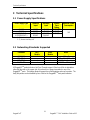
3.1 Power Supply Specifications
Power Supply Type Minimum
Input
Maximum
Input
Internal
Fuse
Rating
Maximum Power
Consumption
24 VDC 18 VDC 36 VDC 3.15A(T)
2
48 VDC 36 VDC 72 VDC 3.15A(T)
2
HI (88/300 VDC)
1
HI (120/240 VAC)
1
88 VDC
85 VAC
300 VDC
264 VAC
3.15A(T)
2
3 W
Notes: 1 – This is the same power supply for both AC and DC.
2 – (T) Denotes time-delay fuse
3.2 Networking Standards Supported
Parameter 10FL
Module
100FX
Module
Notes
IEEE 802.3
10BaseT
IEEE 802.3u
100BaseTX / 100BaseFX
IEEE 802.3x
Full Duplex Operation
TIA/EIA 785
10/100BaseSX Capable
All RuggedMC
TM
products feature Link Pass Through support. When loss of link is detected on
either the fiber side or the copper side, link pulses are no longer transmitted on any of the
RuggedMC
TM
ports. This feature allows for prompt loss of link detection and user correction. The
faulty link partner can be identified by loss of link on the RuggedMC
TM
front panel indicators.
14
RuggedCom
®
RuggedMC™
RMC Installation Guide rev105

Technical Specifications
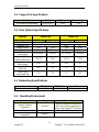
3.3 Copper Port Specifications
Data Port Media Distance Connector Type
10/100 Mbps Auto-negotiating Cat 5 UTP/STP 100m RJ45
3.4 Fiber Optical Specifications
Parameter 10Mbps Ports 100Mps Ports
Multi-Mode Single-Mode* Multi-Mode Single-Mode*
Speed Standard 10BaseFL 100BaseFX
Connector Type ST MTRJ LC
Segment Length 2 km 15 km 2 km 15 km
Optical Wavelength 820nm 1310nm 1300nm 1310nm
Cable Size
Core/Cladding
62.5/125m 9/125m 62.5/125m 9/125m
Optical Tx Power
Min/Max (dBm Peak)
-13.5/-7.6 -23/-15 -16/-11 -15/-8
Optical Rx Sensitivity
(dBm Average)
-34.4 -38 -33.5 -31
Max Optical Rx Power
(dBm Peak)
-8.2 -3.0 -11 -5
Typical Optical
Power Budget (dB)
22 18 17 16.5
* Available as an option
3.5 Networking Specifications
Parameter 10FL Module 100FX Module Notes
Latency
1 S 1 S
Cut-through conversion
3.6 Operating Environment
Parameter Range Comments
Ambient Operating
Temperature
-40 to 85C
Ambient Temperature as measured
from a 30cm radius surrounding the
center of the RuggedMC
TM
enclosure.
Ambient Relative Humidity 5% to 95% Non-condensing
Ambient Storage
Temperature
-40 to 85C
15
RuggedCom
®
RuggedMC™
RMC Installation Guide rev105

Technical Specifications
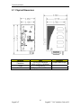
3.7 Physical Dimensions
Parameter Value Comments
Dimensions
3.55 x 2.07 x 3.86 inches
(90,35) x (52,59) x (98,04) mm
(Length x Width x Height)
Weight 1.5 lb (0,68 Kg)
Enclosure 21 gauge Galvanized Steel
16
RuggedCom
®
RuggedMC™
RMC Installation Guide rev105

Type Tests
4 Type Tests
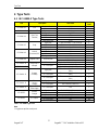
4.1 IEC 61850-3 Type Tests
Test Description Test Levels
Severity
Levels
Enclosure Contact +/- 8kV 4
IEC 61000-4-2 ESD
Enclosure Air +/- 15kV 4
IEC 61000-4-3 Radiated RFI Enclosure ports 20 V/m x
Signal ports +/- 4kV @ 2.5kHz x
D.C. Power ports +/- 4kV 4
A.C. Power ports +/- 4kV 4
IEC 61000-4-4
Burst (Fast
Transient)
Earth ground ports +/- 4kV 4
Signal ports +/- 4kV line-to-earth, +/- 2kV line-to-line 4
D.C. Power ports +/- 2kV line-to-earth, +/- 1kV line-to-line 3
IEC 61000-4-5 Surge
A.C. Power ports +/- 4kV line-to-earth, +/- 2kV line-to-line 4
Signal ports 10V 3
D.C Power ports 10V 3
A.C. Power ports 10V 3
IEC 61000-4-6
Induced
(Conducted) RFI
Earth ground ports 10V 3
40 A/m continuous Note 1
IEC 61000-4-8 Magnetic Field Enclosure ports
1000 A/m for 1 s 5
D.C. Power ports 30% for 0.1s, 60% for 0.1s, 100% for 0.05s N/A
IEC 61000-4-29
30% for 1 period, 60% for 50 periods N/A
IEC 61000-4-11
Voltage Dips &
Interrupts
A.C. Power ports
100% for 5 periods, 100% for 50 periods
2
N/A
Signal ports
2.5kV common, 1kV differential mode @
1MHz
3
D.C. Power ports
2.5kV common, 1kV differential mode @
1MHz
3
IEC 61000-4-12
Damped
Oscillatory
A.C. Power ports
2.5kV common, 1kV differential mode @
1MHz
3
Signal ports 30V Continuous, 300V for 1s 4
IEC 61000-4-16
Mains
Frequency
Voltage
D.C. Power ports 30V Continuous, 300V for 1s 4
IEC 61000-4-17
Ripple on D.C.
Power Supply
D.C. Power ports 10% 3
Signal ports 2kV AC (Fail-Safe Relay output) N/A
D.C. Power ports 1.5kVDC N/A
IEC 60255-5
Dielectric
Strength
A.C. Power ports 2kVAC N/A
Signal ports 5kV (Fail-Safe Relay output) N/A
D.C. Power ports 5kV N/A
IEC 60255-5 H.V. Impulse
A.C. Power ports 5kV N/A
Table 3 - IEC 61850-3 Type Tests
Note:
1. Ruggedcom specified severity levels
17
RuggedCom
®
RuggedMC™
RMC Installation Guide rev105

Type Tests
4.2 IEEE 1613 Type Tests
IEEE Test
IEEE
1613
Clause
Description Test Levels
Enclosure Contact +/- 8kV
C37.90.3 9 ESD
Enclosure Air +/- 15kV
C37.90.2 8 Radiated RFI Enclosure ports 35 V/m
Signal ports +/- 4kV @ 2.5kHz
D.C. Power ports +/- 4kV
A.C. Power ports +/- 4kV
C37.90.1 7 Fast Transient
Earth ground ports +/- 4kV
Signal ports 2.5kV common mode @ 1MHz
D.C. Power ports 2.5kV common & differential mode @ 1MHz
C37.90.1 7 Oscillatory
A.C. Power ports 2.5kV common & differential mode @ 1MHz
Signal ports 5 kV (Failsafe Relay)
D.C. Power ports 5 kV
C37.90 6 H.V. Impulse
A.C. Power ports 5 kV
Signal ports 2kVAC
D.C. Power ports 1.5kVDC
C37.90 6 Dielectric Strength
A.C. Power ports 2kVAC
Table 4 - IEEE 1613 Type Tests
Notes:
If the unit contains copper ports, the IEEE 1613 conformance is Class 1 (During
disturbance, errors may occur but recovery is automatic).
If the unit contains all fiber ports, the IEEE 1613 conformance is Class 2 (During
disturbance, no errors will occur).
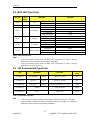
4.3 IEC Environmental Type Tests
Test Description Test Levels
Severity
Levels
IEC 60068-2-1 Cold Temperature Test Ad -40 deg. C, 16 Hours N/A
IEC 60068-2-2 Dry Heat Test Bd +85 deg. C, 16 Hours N/A
IEC 60068-2-30
Humidity (Damp
Heat, Cyclic)
Test Db 95% (non-condensing), 55°C, 6 cycles N/A
IEC 60255-21-1 Vibration 2g @ (10-150) Hz Class 2
IEC 60255-21-2 Shock 30g @ 11 ms Class 2
Table 5 - Environmental Type Tests
Note:
Class 2 refers to “Measuring relays and protection equipment for which a very high
security margin is required or where the vibration levels are very high, (e.g. shipboard
application and for severe transportation conditions).”
18
RuggedCom
®
RuggedMC™
RMC Installation Guide rev105

Agency Approvals
19
RuggedCom
®
RuggedMC™
RMC Installation Guide rev105
5 Agency Approvals
Agency Standards Comments
cCSAus, CE
CSA C22.2 No. 60950, UL 60950,
EN 60950, EN 61000-6-2
PENDING
6 Warranty
Five (5) years from date of purchase, return to factory. For warranty details, visit
www.ruggedcom.com or contact your customer service representative.
Should this product require warranty or service, contact the factory at:
RuggedCom Inc.
300 Applewood Crescent
Concord, Ontario
Canada L4K 5C7
Phone: +1 905 856 5288
Fax: +1 905 856 1995
-
 1
1
-
 2
2
-
 3
3
-
 4
4
-
 5
5
-
 6
6
-
 7
7
-
 8
8
-
 9
9
-
 10
10
-
 11
11
-
 12
12
-
 13
13
-
 14
14
-
 15
15
-
 16
16
-
 17
17
-
 18
18
-
 19
19


RuggedCom MEDIACONVERTER Installation guide
- Category
- Network switches
- Type
- Installation guide
- This manual is also suitable for
Ask a question and I''ll find the answer in the document
Finding information in a document is now easier with AI
Related papers
-
RuggedCom RUGGEDSWITCH RS900G Installation guide
-
-
-
-
-
-
-
-
-
Other documents
-
Radiant Communications DL221 Series User manual
-
Siemens RUGGEDCOM RS950G Installation guide
-
Moxa IMC-21-M-ST-FL Datasheet
-
 Versitron S7085x Owner's manual
-
Transition Networks Network Card E-TBT-FRL-01 User manual
-
Lantronix XPress-Pro SW 52012F User manual
-
Lantronix XPress-Pro SW 52012F User manual
-
Interlogix SuperBus 2000 Voice Module Installation guide
-
 Sel SEL-2243 User manual
-

