Page is loading ...

Constant Pressure System
Installation and Operating
Instructions
ATTENTION: Please refer to www.bit.ly/dynadrive
for any product information updates, or simply
scan this QR code.
These can also be found on the product nameplate.
Please pass these instructions on to the operator of this equipment.
READ AND SAVE THESE INSTRUCTIONS.
Dyna
Drive
™
Models:
DD60-10(CE)
DD60-10NPT
DD90-11(CE) DD90-11NPT

2
Dyna
Drive
™
Congratulations on your purchase of a high quality, Davey DynaDrive constant pressure system.
All components have been designed and manufactured to give trouble free, reliable operation.
Contents
1. PRIOR TO USING THIS PRESSURE SYSTEM, YOU MUST ENSURE THAT ..........................................3
2. YOUR NEW SYSTEM .................................................................................................................................3
3. APPLICATIONS ..........................................................................................................................................4
3.1 Above ground water sources (flooded suction) .....................................................................................4
3.2 In-ground water sources (eg suction lift from in ground tank) ...............................................................4
3.3 Spear point installations ........................................................................................................................4
3.4 Connecting mains scheme or town water supply to either suction,
or discharge of pumps and pressure systems ......................................................................................4
3.5 Installs with a mains pressure hot water system ...................................................................................5
4. INSTALLATION ...........................................................................................................................................5
4.1 Choosing a site ......................................................................................................................................5
4.2 Pipe connections ...................................................................................................................................5
4.3 DynaDrive with air handling capacity ....................................................................................................6
4.4 Power connection ..................................................................................................................................6
4.5 The pressure tank .................................................................................................................................7
5. FEATURES .................................................................................................................................................8
5.1 System features ....................................................................................................................................8
5.2 DynaDrive display layout .......................................................................................................................8
5.3 VSD features .........................................................................................................................................9
6. OPERATION ...............................................................................................................................................9
6.1 Start-up procedure ................................................................................................................................9
6.2 Manual override ...................................................................................................................................11
6.3 Main menu display ..............................................................................................................................13
6.4 Changing the set pressure ..................................................................................................................14
6.5 Extra draw-off capacity ........................................................................................................................16
6.6 Decommissioning the DynaDrive ........................................................................................................16
7. ADVANCED SETTINGS ............................................................................................................................17
7.1 Changing cut-in pressure point ...........................................................................................................17
7.2 Changing the min frequency ...............................................................................................................18
7.3 Using a switch to override DynaDrive operation .................................................................................20
7.4 Daisy-chain multiple DynaDrive systems ............................................................................................23
8. TECHNICAL SPECIFICATIONS ...............................................................................................................25
8.1 Operating limits ...................................................................................................................................25
8.2 Hydraulic performance ........................................................................................................................25
8.3 Dimensions ..........................................................................................................................................26
8.4 Electrical data ......................................................................................................................................26
8.5 Materials of construction .....................................................................................................................26
10. MAINTENANCE ........................................................................................................................................27
10.1 Periodic pressure tank checks ..........................................................................................................27
11. TROUBLESHOOTING ..............................................................................................................................28
12. SPARE PARTS ..........................................................................................................................................28
13. DAVEY WARRANTY .................................................................................................................................31
13.1 Warranty inside the USA ...................................................................................................................31
13.2 Warranty inside the USA ...................................................................................................................32

3
CAUTION: This pump has been evaluated for use with water only. Do not insert any object
in the opening. Before using this pump, the pump must be well installed. Children should
be supervised that they do not play with the pump. NPT model variants acceptable for
indoor use only, do not used outdoor. For use with maximum 80°C (176°F) water.
WARNING: Risk of electric shock. This pump is supplied with a grounding conductor
and grounding-type attachment plug. To reduce the risk of electric shock, be certain
that it is connected only to a properly grounded, grounding-type receptacle. Non-
submersible pump. This pump has not been investigated for use in swimming pool or
marine areas. To reduce risk of electric shock, pull plug before servicing or cleaning
this pump. Do not operate this pump with wet hands.
ATTENTION: The DynaDrive system and associated pipework operate under pressure.
Under no circumstances should the DynaDrive system, or associated pipework be
disassembled unless the internal pressure of the system has been relieved. Failure to
observe this warning will expose persons to the possibility of personal injury and may
also result in damage to the pump, pipework or other property.
This appliance is not intended for use by persons (including children) with reduced
physical, sensory or mental capabilities, or lack of experience and knowledge, unless
they have been given supervision or instruction concerning use of the appliance by a
person responsible for their safety. Children should be supervised to ensure that they
do not play with the appliance. This appliance can be used by children from aged 8
years and above and persons with reduced physical sensory, mental capabilities, or
lack of experience and knowledge if they have been given supervision, or instruction
concerning use of the appliance in a safe way and understand the hazards involved.
Maximum pressure limited to 64m (210 feet) total head.
IMPORTANT: If the supply cord is damaged, it must be replaced by the manufacturer,
its service agent, or similarly qualied persons in order to avoid a hazard. Pump is to
be supplied through a residual current device (RCD) having a rated residual operating
current not exceeding 30mA. Cleaning and user maintenance shall not be made by
children without supervision. Children shall not play with the appliance.
Prior to installation remove the inlet and outlet pipe transport plugs & associated seals from the suction
and/or discharge ports.
1. PRIOR TO USING THIS PRESSURE SYSTEM, YOU MUST ENSURE THAT
• The pump is installed in a safe and dry environment
• The pump enclosure has adequate drainage in the event of leakage
• Any transport plugs are removed
• The pipework is correctly sealed and supported
• The pump is primed correctly
• The power supply is correctly connected
• All steps have been taken for safe operation
Appropriate details for all these items are contained in the following Installation and Operating Instructions.
Read these in their entirety before switching on this pump. If you are uncertain as to any of these Installation
and Operating Instructions, please contact your Davey dealer, or the appropriate Davey office as listed on
the back of this document.
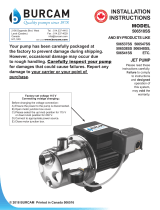
2. YOUR NEW SYSTEM
1. Suction inlet
2. Pump body
3. Pump priming plug
4. Discharge/delivery outlet
5. DynaDrive control module
6. Motor
7. Pressure tank
(optional extra for CE model variants)
Figure 2.1
DD60-10, DD90-11

4
3. APPLICATIONS
3.1 Above ground water sources (flooded suction)
Installations with flooded suction require a gate valve so water supply can be
turned off for pump removal and servicing, see figure 3.1. There is no need
to install a one-way check valve in the suction pipeline as there is a one-way
check valve installed in the tee piece immediately on top of the DynaDrive
pump discharge.
3.2 In-ground water sources (eg suction lift from in ground tank)
Whenever the installation position of the pump is higher than the lowest
water level, a foot valve should be fitted to the end of the suction pipe, see
figure 3.2. Ensure that the foot valve is at least ½ metre (1⅔ feet) below
minimum water level to avoid a vortex of air being drawn into pipe.
In suction lift installations that have an unreliable foot-valve it may
be preferable to remove the check valve in the DynaDrive discharge
tee piece. Doing so will allow the DynaDrive pressure transducer to
“recognise” a loss of water from a suction line, while the DynaDrive
is in standby. Applications of this nature, with long &/or wide suction
lines consist of a considerable volume of water, ie > 100 litres (26
US gallons) in the suction pipe. Temperature variations of the water
may create fluctuations in the pressure of the water, falsely triggering
the DynaDrive to start/stop. In such as case, it is worth considering
upsizing the pressure tank to help absorb these pressure fluctuations. If
concerned, please consult your Davey representative.
3.3 Spear point installations
When a pump is installed on a spear, or well point, a check valve fitted immediately
on top of the spear point itself, see figure 3.3. Do not install the check valve at the
pump, or at the top of the well. Do not run the pump without water in it.
In suction lift installations that have an unreliable foot-valve it may be preferable to
remove the check valve in the DynaDrive discharge tee piece. Doing so will allow
the DynaDrive pressure transducer to “recognise” a loss of water from a suction line,
while the DynaDrive is in standby. Applications of this nature, with long &/or wide
suction lines consist of a considerable volume of water, ie > 100 litres (26 US gallons)
in the suction pipe. Temperature variations of the water may create fluctuations in
the pressure of the water, falsely triggering the DynaDrive to start/stop. In such as
case, it is worth considering upsizing the pressure tank to help absorb these pressure
fluctuations. If concerned, please consult your Davey representative.
3.4 Connecting mains scheme or town water supply to either
suction, or discharge of pumps and pressure systems
Most Water Supply Authorities have strict regulations
regarding direct connection of pumps to mains water
supplies. In most cases an isolating tank is required
between mains supply and pump, see figure 3.4. Davey
also recommend this method. Directly applied mains
pressure can exceed pump operating pressure and
damage pump. Davey Water Products Pty Ltd cannot
accept responsibility for loss, or damage resulting from
incorrect, or unauthorized installations.
MAINS WATER
Figure 3.1
MAINS WATER
Figure 3.4
Figure 3.2
> 1m
> 0.5m
Foot valve
(Not Supplied)
Figure 3.3
Check valve

5
3.5 Installs with a mains pressure hot water system
ATTENTION: Always ensure hot water systems are installed in compliance with
manufacturers recommendations and in accordance with all local regulations.
To protect your system from damage caused by back pressure from hot
water systems, see figure 3.5. You should always have installed on the hot
water inlet an approved non-return valve.
Davey Water Products Pty Ltd cannot accept responsibility for loss or
damage resulting from incorrect, or unauthorised installations.
4. INSTALLATION
4.1 Choosing a site
Choose a clean and dry site with a firm base as close to the water source as possible with correct power
supply. Make sure your pump is always connected to an adequate, reliable source of clean water. To protect
your pump from the weather, make sure the pump house is both waterproof, frost free and has adequate
ventilation. The pump should be mounted on a firm base allowing for drainage, to avoid damage to flooring etc.,
that over time may occur from leaking pipe joints or pump seals. Do not mount the pump vertically. Never place
flammable materials on, or near your pump.
The pressure that DynaDrive comes pre-set to is as follows:
* DD60-10(CE) 400kPa (58psi);
* DD90-11(CE) 400kPa (58psi);
* DD60-10NPT 414kPa (60psi); or
* DD90-11NPT 414kPa (60psi).
However, it is possible to adjust the pressure set point. Some plumbing authorities impose a pressure limitation
on the pressure of water into a dwelling. Consideration of operating pressures should also be given to
appliances within the dwelling. If unsure, check with local authorities, or a licenced contractor.
4.2 Pipe connections
IMPORTANT: Suction leaks are the largest cause of poor pump performance and are
difcult to detect. Ensure all connections are completely sealed using thread tape only.
DO NOT USE SEALING COMPOUNDS, HEMP, OR PIPE DOPE.
For best performance use P.V.C, or polythene pipe
with a diameter at least the same as the pump’s
inlet. Larger diameter pipe may be used to minimise
resistance to flow when pumping for distances longer
than 5m (16’). Use unions at pipe connections to
enable easy removal and servicing.
Use enough “plumbers’ tape” to ensure airtight seal
and hand tighten only, do not screw connections all
the way into suction port, see figure 4.1. To prevent
strain on pump
thread always
support heavy inlet and outlet pipes.
Lay suction pipe at a constant gradient to avoid air pockets which may reduce
pump efficiency, see figure 4.2.
Avoid installing 90° elbows before the suction inlet of the pump, within a
distance equivalent to 5 x pipe diameter. For example: using 40mm (1½”)
suction pipe, avoid installing a 90° elbow within 200mm (7¾”) of the pump inlet.
This will assist laminar flow.
Figure 3.5
Figure 4.1
Figure 4.2

6
4.3 DynaDrive with air handling capacity
Your DynaDrive has the benefit of a new upgraded self-priming and air handling capability. While Davey must
stress the overall requirement for all suction lines to be airtight, we also are aware that sometimes removing
air from suction lines or stopping minor leaks can be difficult. For this reason, Davey have incorporated
special features into your new pump or pressure system to make operation easier and more dependable.
To help you get the most from this new capability please read this addendum in conjunction with the full
Installation and Operating Manual included with your pump.
Plumbing: Pay special attention to ensuring the suction pipe and associated fittings are airtight. The absence
of a water leak on the suction line may not confirm that the pipe or fittings are airtight.
Should the suction line contain air pockets it can aid the priming process greatly if you can temporarily isolate
the discharge line from the pump and instead use an adjacent tap to allow the pump to discharge water until full
prime is established. Such a facility is also useful for future servicing and troubleshooting should it be required.
Priming: Filling the pump and suction line with water is made much easier by filling from the outlet side and
allowing any trapped air in the pump to evacuate via one of the plugged holes on the pump casing.
• Remove the tee piece on the top of the pump when trying to fill as this contains a check (one-way) valve,
that won’t otherwise allow water to enter the pump casing;
• Remove priming plug and fill casing and suction line (on flooded suction, simply open gate valve to
pump). When full, replace priming plug;
• Ensure outlet nearest to pump is open;
• Ensure all valves in suction line are open;
• Switch on power. All LEDs on the display will flash;
• Refer section “6.1 Start Up Procedure”. A full flow of water should be discharged from the open tap.
4.4 Power connection
IMPORTANT: Long extension leads should be avoided as they often have insufcient
current carrying capacity to run electric motors, hence they can cause substantial
voltage drop and operating problems.
If the electrical fittings in your country make it necessary to remove the plug from the lead fixed to the motor
care should be taken to ensure that the earth conductor green/yellow in the lead is properly connected to
a good earth. CAUTION: For models DD60-10NPT and DD90-11NPT, compliance dictates removal of the
power cord and plug is not allowable.
ATTENTION: Ensure that any and all electrical work is only undertaken by an
authorized electrician.
The electrical connections and checks must be made by a qualified electrician and comply with applicable
local standards. Poor installation, or poor power supply may even result in electrical fires!
ATTENTION: Automatic reset thermal overloads will allow the pump to restart without
warning. ALWAYS disconnect the pump motor from the electrical supply before
maintenance or repairs.
NOTE:
• Ensure motor is connected to power supply specified on nameplate;
• Although the Davey electric motor is specifically engineered to perform on a range of power supply
voltages, malfunctions or failure caused by adverse voltage supply conditions are not covered under
guarantee.
ATTENTION: We are obliged to inform you that this pump is not to be used by children,
or inrm persons and must not be used as a toy by children. Some insects such as
small ants, nd electrical devices attractive for various reasons. If your pump enclosure
is susceptible to insect infestation you should implement a suitable pest control plan.

7
4.5 The pressure tank
IMPORTANT: Air pressure in pressure tank should be set to 70% of the DynaDrive set
pressure. For example, the pressure that DynaDrive comes pre-set to is as follows:
DD60-10(CE) 400kPa (58psi);
DD90-11(CE) 400kPa (58psi);
DD60-10NPT 414kPa (60psi); or
DD90-11NPT 414kPa (60psi).
The default air pressure of the pressure tank used with DynaDrive should be set to:
DD60-10 280kPa (41psi);
DD90-11 280kPa (41psi);
DD60-10CE 280kPa (41psi) tank purchased separately;
DD90-11CE 280kPa (41psi) tank purchased separately;
DD60-10NPT 290kPa (42psi); or
DD90-11NPT 290kPa (42psi)
Never over-charge the tank. Always use air at ambient temperature. Do not overtighten.
During air replenishment the tank should be externally inspected. Any signs of leakage
from the tank may indicate a need for immediate replacement.
If air charge adjustment is required, then follow these procedures:
• Remove the pressure tank completely from pump installation, ensuring to isolate the pressure tank and
release the water pressure from the tank beforehand; or
• Release all water pressure from the pressure tank by switching off the pump at the power point and
opening the closet tap. For above ground supply tanks, it is necessary to close the gate valve between
the supply tank and the pump;
ATTENTION: To prevent personal injury, ensure all water pressure is released from the
pressure system prior to work being performed.
• Leave tap open during air replenishment;
• When all water pressure has been released from the system, check air pressure at air valve on top of
pressure tank. The pre-charge pressure reading should be 70% of set point pressure;
• If necessary, replenish air charge to the correct pressure indicated. Ensure that a tap in outlet piping of
pump is open during replenishment of air pre-charge.

8
5. FEATURES
5.1 System features
• Provides warning indications for system faults;
• Has adjustable pressure setting to allow for various operating conditions;
• Provides automatic “cut-out” protection should the pump run out of water, should the pump fail to start
due to low voltage or a blockage in the pump;
• Enables the pump to deliver a constant pressure of water particularly across a wide range of flow rates –
reducing the inconvenience of pressure variation in showers etc.
* Allows for independent switch to override DynaDrive operation. This could be particularly handy if using a
float switch in a source tank;
* Allows for remote alarm monitoring;
* Allows for daisy-chain multiple DynaDrive systems; and
* Allows for adjustment of cut-in pressure. This could be particularly handy in applications with slow leaks.
5.2 DynaDrive display layout
Figure 5.1
P/ N :16115-1 B
Prime Button
Automatic on / manual off button
Prime LED
Automatic LED
Menu button
Enter button
Menu up button
Menu down button
Power LED
Fault LED

9
5.3 VSD features
• Auto reset after dry run detected;
• Auto reset after loss of power;
• Option for adapting (volt-free) tank level sensor into programming;
• Control and information panel with LCD screen;
• Includes pressure transducer;
• Under current visual alarm;
• Over current protection by way of shut down and visual alarm;
• Data logging of operation controls and alarms including run duration;
• Aluminum heat exchanger;
• VSD cooling by pump’s fan, lowering cooling costs by way of additional fans;
• Motor and VSD protection from onsite “brown-outs” by way of shut down, visual alarm & auto re-try after
correct voltage regained;
• Protection from motor locked rotor by way of auto shut down;
• Adaptable for daisy-chain multiple pumps in parallel, up to 2 pumps;
• Fault diagnosing software for user troubleshooting;
• Adjustable pressure set points via easy to use touchpad in 10kPa (1½psi) increments;; and
• 3-minute manual override for priming.
6. OPERATION
6.1 Start-up procedure
After power is initially turned on to the DynaDrive, the display shows the software version and the name
Davey, see figure 6.1. All LEDs flash for the initial ~ 5 seconds. The
Power LED will remain lit green,
showing the DynaDrive has power.
Figure 6.1
P/ N :16115 -1 B
DAVEY
VER. 0 1

10
The display then reverts to the HOME SCREEN, see figure 6.2. The
Power LED will show bright green.
The display shows the pre-set pressure on the top line, shown in Figure 6.2, and pressure being measured
by the DynaDrive pressure transducer on the bottom line, shown in Figure 6.2.
The default unit of measurement is as follows:
* DD60-10(CE): kPa;
* DD90-11(CE): kPa;
* DD60-10NPT: psi; or
* DD90-11NPT: psi.
Figure 6.2
P/ N :16115 -1 B
Pset 400
Pact 0
To start the DynaDrive:
• Pushing the
Automatic on / manual off button toggles between automated control and manual off;
• Pushing the
Automatic on / manual off button will turn on the pump and it will continue to pump
water until set pressure is achieved, see figure 6.3;
Figure 6.3
P/ N :16115 -1 B
Pset 400
Pact 400

11
• The
Automatic LED will illuminate bright green indicating that the pump is running
Once the set pressure has been achieved, the DynaDrive will slow the motor speed. If the pressure drops
below set pressure, the motor speed will increase again to maintain pressure. However, if the pressure does
not drop below set pressure, the motor speed will continue to decrease, until it’s off.
The
Automatic LED will flash green to indicate the pump is in standby maintaining pressure, see
figure 6.4.
Figure 6.4
P/ N :16115 -1 B
Pset 400
Pact 400
6.2 Manual override
In addition to automated control, DynaDrive can also be run in manual override on, should the need arise.
IMPORTANT: It should be noted that when the pump is manually turned on, the
automated protection built into DynaDrive is overridden. Davey recommends use of the
manual override only when absolutely necessary and only for a short time period.
To switch to manual override on:
• Ensure automated control is turned off. To turn the automated control off, push the
Automatic on /
manual off button.
• The green
Automatic LED will turn off, see figure 6.5;

12
Figure 6.5
P/ N :16115 -1 B
Pset 400
Pact 400
• Press and hold the Prime button. The pump will turn on and continue to run until the
Prime button is released, see figure 6.6;
While the pump is in manual override the
Prime LED will illuminate orange, see figure 6.6.
Figure 6.6
P/ N :16115 -1 B
Pset 400
Pact 420

13
6.3 Main menu display
After initial startup, pressing the
Menu up button will allow display to scroll through the following:
• Frequency (Hz);
• Outgoing current per phase from the DynaDrive to the pump’s motor (Amps);
• Temperature of the DynaDrive (°C).
To change the display:
• Press the
Menu up button;
• The display will continue to show the pressure set, but changes from showing actual pressure, to the
frequency of power supplying the motor, see figure 6.7. This dictates the speed that the motor runs;
Figure 6.7
P/ N :16115 -1 B
Pset 400
Hz 4 1
• Pressing the
Menu up button again will display the motor current draw per phase, and the
temperature of the DynaDrive controller, see figure 6.8;
Figure 6.8
P/ N :16115 -1 B
A 1,7
ºC 50
• To change the display back to normal, scroll back through the menu by pressing the
Menu down
button twice.

14
6.4 Changing the set pressure
IMPORTANT: WHEN ADJUSTING SET PRESSURE, DO NOT EXCEED THE PRESSURE
CAPABLE OF THE DYNADRIVE IN THE GIVEN INSTALLATION. REFERENCE TO AS/NZS
3500/2003 (OR LOCAL EQUIVALENT) SHOULD ALSO BE CONSIDERED. When changing
the set pressure of DynaDrive, the pressure of the pressure tank must also be adjusted.
Refer to section 4.5 pressure tank, of the installation chapter.
The set pressure cannot be changed while the pump is running, or in automatic mode.
To change the set pressure:
• Ensure automated control is turned off. To turn the automated control off, push the
Automatic on /
manual off button.
• The green
Automatic LED will turn off, see figure 6.5;
Figure 6.9
P/ N :16115 -1 B
Pset 400
Pact 400
• Once the motor has slowed to a stop, press and hold the Menu button for ~ 5 seconds. The display
will change to show your current set pressure, see figure 6.10;

15
Figure 6.10
P/ N :16115 -1 B
pressure
400 kPa
• If the controls are untouched for ~ 30 seconds, the menu will revert back to normal display;
• To change the set pressure, use the
Menu up button or
Menu down button.
Pressure changes are in multiples of 10kPa for DD60-10(CE) and DD90-11(CE) models,
and 5psi for NPT model variants.
• Once you’ve reached your new set point, see figure 6.11;
Figure 6.11
P/ N :16115 -1 B
pressure
300 kPa
• Press Enter button, or Menu button to return to the HOME SCREEN, see figure 6.12;

16
Figure 6.12
P/ N :16115 -1 B
pset 300
pact 380
• Now restart automatic operation by pressing Automatic on / manual off button.
6.5 Extra draw-off capacity
The DynaDrive has a pressure tank included as part of the system which will accommodate small leaks.
In some applications it may be appropriate to install an additional (or larger) accumulator (pressure tank)
capacity. These applications include:
• Long suction lines;
• Low flow appliances connected to the pump, such as evaporative air conditioners, slow filling toilet
cisterns, where flows can be a little as 0.5L/min (½ quart).
Any additional accumulators can be installed downstream of the controller (ie. between the controller and the
first outlet). Where extra draw-off capacity is utilised the additional pressure tank should have a pre-charge 70%
of the system set pressure. For installations requiring flow rates between 125-500mL/min (4 – 17oz/min), it is
common for the DynaDrive to run continuously. If this occurs, adjust up the min frequency setting (refer section
7.4) and install a larger pressure tank. If you have any further concerns, please contact your local Davey
representative.
6.6 Decommissioning the DynaDrive
Should it become necessary to decommission the DynaDrive to relocate the it, store it, or conduct some
service maintenance for example:
• Turn off the power to the DynaDrive and unplug it from electrical supply;
• Close any isolation valves on the suction side of the pump;
• Open a tap, or outlet on the delivery side of the pump and discharge excess pressure in the line;
• Close any isolation valves on the delivery side of the pump;
ATTENTION: It is essential that the system is de-pressurized before proceeding.
Failure to do so could result in harm to product &/or user.
• Unscrew the pressure tank from the top of the DynaDrive discharge/delivery outlet. NOTE: depending on
the installation it is possible that water may spill from the pipework and pressure tank. It would be good
practice to prepare for this;
• Unscrew pipework from the DynaDrive discharge/delivery outlet;
• Unscrew pipework from the DynaDrive suction inlet;
• Slide DynaDrive out of location.

17
7. ADVANCED SETTINGS
7.1 Changing cut-in pressure point
The default cut-in pressure of DynaDrive is 50kPa (7psi) less than set point. This can be changed by:
• Ensure automated control is turned off. To turn the automated control off, push the
Automatic on /
manual off button.
• The green
Automatic LED will turn off, see figure 7.1;
Figure 7.1
P/ N :16115-1 B
Pset 400
Pact 400
• Once the motor has slowed to a stop, press and hold the Menu button and Enter button for ~
5 seconds. The display will change to show your current set pressure, see figure 7.2;
Figure 7.2
P/ N :16115-1 B
pressure
400 kPa

18
• If the controls are untouched for ~ 30 seconds, the menu will revert back to normal display;
• Using the
Menu up button and
Menu down button scroll through to Cut-in;
• Use the
Menu up button and
Menu down button to change the setting to adjust the cut-in
pressure variance;
• Press the
Enter button to save settings and return to the HOME SCREEN;
• Now restart automatic operation by pressing
Automatic on / manual off button.
In a daisy-chain installation, the cut-in of the secondary pump occurs after the same pressure drop as the
primary pump is set.
7.2 Changing the min frequency
The default minimum frequency of DynaDrive is 15Hz. This can be changed by:
• Ensure automated control is turned off. To turn the automated control off, push the
Automatic on /
manual off button.
• The green
Automatic LED will turn off, see figure 7.3;
Figure 7.3
P/ N :16115 -1 B
Pset 400
Pact 400
• Once the motor has slowed to a stop, press and hold the Menu button and Enter button for ~
5 seconds. The display will change to show your current set pressure, see figure 7.4;

19
Figure 7.4
P/ N :16115 -1 B
pressure
400 kPa
• If the controls are untouched for ~ 30 seconds, the menu will revert back to normal display;
• Using the
Menu up button and
Menu down button scroll through to Min Freq.
• Use the
Menu up button and
Menu down button to change the setting to. The setting will
change by 5Hz;
• Press the
Enter button to save settings and return to the HOME SCREEN;
• Now restart automatic operation by pressing
Automatic on / manual off button.

20
7.3 Using a switch to override DynaDrive operation
DynaDrive has the ability to be overridden by a separate switch. This may be of benefit if using a float switch
on a source tank (eg rainwater tank). To wire in an independent switch, refer figure 7.5 and 7.6.
Figure 7.5
Figure 7.6
/