Page is loading ...

Furnnox
Burner
210 Installation Guide
2/14/2011
Version 1

2
Copyright
Copyright 2007 by Eclipse, inc. All rights reserved
worldwide. This publication is protected by federal
regulation and shall not be copied, distributed,
transmitted, transcribed or translated into any human or
computer language, in any form or by any means, to any
third parties, without the express written consent of
Eclipse, inc.
Disclaimer Notice
In accordance with the manufacturer’s policy of continual
product improvement, the product presented in this
brochure is subject to change without notice or obligation.
The material in this manual is believed adequate for the
intended use of the product. If the product is used for
purposes other than those specified herein, confirmation
of validity and suitability must be obtained. Eclipse
warrants that the product itself does not infringe upon any
United States patents. No further warranty is expressed or
implied.
Liability & Warranty
We have made every effort to make this manual as
accurate and complete as possible. Should you find errors
or omissions, please bring them to our attention so that we
may correct them. In this way we hope to improve our
product documentation for the benefit of our customers.
Please send your corrections and comments to our
Marketing Communications Manager.
It must be understood that Eclipse’s liability for its product,
whether due to breach of warranty, negligence, strict
liability, or otherwise is limited to the furnishing of
replacement parts and Eclipse will not be liable for any
other injury, loss, damage or expenses, whether direct or
consequential, including but not limited to loss of use,
income, or damage to material arising in connection with
the sale, installation, use of, inability to use, or the repair
or replacement of Eclipse’s products.
Any operation expressly prohibited in this manual, any
adjustment, or assembly procedures not recommended or
authorized in these instructions shall void the warranty.
Document Conventions
There are several special symbols in this document. You
must know their meaning and importance.
The explanation of these symbols follows below. Please
read it thoroughly.
How To Get Help
If you need help, contact your local Eclipse representative.
You can also contact Eclipse at:
1665 Elmwood Rd.
Rockford, illinois 61103 U.S.A.
Phone: 815-877-3031
Fax: 815-877-3336
http://www.eclipsenet.com
Please have the information on the product label available
when contacting the factory so we may better serve you.
Product Name
Item #
S/N
DD MMM YYYY
www.eclipsenet.com
This is the safety alert symbol. It is used to alert you to potential personal
injurt hazards. Obey all safety messages that follow this symbol to avoid
possible injury or death.
Indicates a hazardous situation which, if not avoided, will result in death
or serious injury.
Indicates a hazardous situation which, if not avoided, could result in
death or serious injury.
Indicates a hazardous situation which, if not avoided, could result in
minor or moderate injury.
Is used to address practices not related to personal injury.
Indicates an important part of text. Read thoroughly.
NOTE
NOTICE
CAUTION
WARNING

3
Eclipse Furnnox Burner, V1, Installation Guide 210, 2/14/2011
1 Introduction............................................................................................................................ 4
Product Description .............................................................................................................. 4
Audience .............................................................................................................................. 4
Purpose................................................................................................................................ 4
Related Documents.............................................................................................................. 4
2 Safety...................................................................................................................................... 5
Safety Warnings ................................................................................................................... 5
Capabilities........................................................................................................................... 5
Operator Training ................................................................................................................. 5
Replacement Parts...............................................................................................................5
3 Installation.............................................................................................................................. 6
Introduction........................................................................................................................... 6
Handling & Storage ..............................................................................................................6
Checklist Before Installation ................................................................................................. 7
Position of Components ....................................................................................................... 6
Approval of Components...................................................................................................... 6
Electrical Supply................................................................................................................... 7
Prepare the Burner............................................................................................................... 7
Combustion Block Installation .............................................................................................. 8
Checklist After Installation ....................................................................................................10
Refractory Block Curing Schedule ....................................................................................... 10
4 Adjustment, Start & Stop ......................................................................................................11
Modulating Gas & Air Ratio System ..................................................................................... 11
Set the Bypass Pilot Gas (Optional)..................................................................................... 13
Start Procedure .................................................................................................................... 14
Stop Procedure .................................................................................................................... 14
5 Maintenance & Troubleshooting.......................................................................................... 15
Introduction........................................................................................................................... 15
Maintenance......................................................................................................................... 15
Monthly Checklist ................................................................................................................. 15
Yearly Checklist.................................................................................................................... 15
Troubleshooting Guide......................................................................................................... 16
Appendix ................................................................................................................................... i
Conversion Factors ..............................................................................................................i
Table of Contents

4
Eclipse Furnnox Burner, V1, Installation Guide 210, 2/14/2011
Product Description
The Furnnox is a Low NOx nozzle-mix burner using
ambient or preheated combustion air with temperatures
up to 1100°F (600°C). The Furnnox burner is designed for
application on direct fired high temperature range, 1400°F
to 2800°F (760°C to 1540°C), furnaces.
By staging the combustion air the burner NOx emissions
are reduced compared to standard nozzle mixing burners.
Staging of the combustion air is achieved by secondary air
holes in the burner refractory block.
The Furnnox burner is designed for direct ignition and
flame supervision by UV scanner.
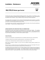
Figure 1.1. Standard & Insulated Furnnox Burner
Audience
This manual has been written for personnel already
familiar with all aspects of a gas burner and it’s add-on
components, also referred to as the burner package.
These aspects are:
• Installation
• Use
• Maintenance
• Safety
The audience is expected to be qualified and have
experience with this type of equipment and its working
environment.
Purpose
The purpose of this manual is to make sure that you carry
out the installation of a safe, effective and trouble-free
system.
Furnnox Documents
Installation Guide No. 210
• This document
Datasheet Series No. 210
• Available for individual Furnnox models
• Required to complete installation
Spare Parts List Series No. 210
• Recommended replacement part information
Related Documents
• EFE 825 (Combustion Engineering Guide)
• Eclipse Bulletins and Information Guides: 210, 610,
710, 720, 730, 742, 744, 760, 930, I-354
BLOCK UP
BLOCK DOWN
Standard
Insulated
1
Introduction

5
Safety
Important notices which help provide safe burner
operation will be found in this section. To avoid personal
injury and damage to the property or facility, the following
warnings must be observed. All involved personnel should
read this entire manual carefully before attempting to start
or operate this system. If any part of the information in this
manual is not understood, contact Eclipse before
continuing.
Safety Warnings
■ The burners, described herein, are designed to mix
fuel with air and burn the resulting mixture. All fuel
burning devices are capable of producing fires and
explosions if improperly applied, installed,
adjusted, controlled or maintained.
■ Do not bypass any safety feature; fire or explosion
could result.
■ Never try to light a burner if it shows signs of
damage or malfunction.
■ The burner and duct sections are likely to have
HOT surfaces. Always wear the appropriate
protective equipment when approaching the
burner.
■ Eclipse products are designed to minimize the use
of materials that contain crystalline silica.
Examples of these chemicals are: respirable
crystalline silica from bricks, cement or other
masonry products and respirable refractory
ceramic fibers from insulating blankets, boards, or
gaskets. Despite these efforts, dust created by
sanding, sawing, grinding, cutting and other
construction activities could release crystalline
silica. Crystalline silica is known to cause cancer,
and health risks from the exposure to these
chemicals vary depending on the frequency and
length of exposure to these chemicals. To reduce
the risk, limit exposure to these chemicals, work in
a well-ventilated area and wear approved personal
protective safety equipment for these chemicals.
■ This manual provides information regarding the
use of these burners for their specific design
purpose. Do not deviate from any instructions or
application limits described herein without written
approval from Eclipse.
Capabilities
Only qualified personnel, with sufficient mechanical
aptitude and experience with combustion equipment,
should adjust, maintain or troubleshoot any mechanical or
electrical part of this system.
Operator Training
The best safety precaution is an alert and trained
operator. Train new operators thoroughly and have them
demonstrate an adequate understanding of the
equipment and its operation. A regular retraining schedule
should be administered to ensure operators maintain a
high degree of proficiency.
Replacement Parts
Order replacement parts from Eclipse only. All Eclipse
approved valves or switches should carry UL, FM, CSA,
CGA and/or CE approval where applicable.
DANGER
WARNING
NOTICE
2

6
Eclipse Furnnox Burner, V1, Installation Guide 210, 2/14/2011
Introduction
In this section you will find the information and instructions
needed to install the burner and system components.
■ Only qualified competent personnel with
experience of combustion systems are allowed to
install, adjust or maintain the burner.
■ All installation work must be carried out in
compliance with current legislated standards.
Handling & Storage
Handling
• Make sure the area is clean.
• Inspect the burner, ensure that all components are
clean and free from damage.
• Use appropriate support and handling equipment
when lifting the burner.
• Protect the burner from weather, damage, dirt and
moisture.
• Protect the burner and components from excessive
temperatures and humidity.
Storage
• Make sure the components are clean and free of
damage.
• Store the components in a cool, clean, dry room.
• After making sure everything is present and in good
condition, keep the components in original
packages as long as possible.
Position of Components
The position and amount of components are determined
by the kind of control method chosen. Furnnox burners
are applied on furnaces using multiple burners and
multiple control zones, for which electronic gas air ratio
control systems are used.
Due to the variety of these control systems this manual
does not describe the design.
Approval of Components
Limit Controls & Safety Equipment
All limit controls and safety equipment must comply with
all applicable local codes and/or standards and must be
listed for combustion safety by an independent testing
agency. Typical application examples include:
• American: NFPA 86 with listing marks from UL, FM,
CSA
• European: EN 746-2 with CE mark from TuV,
Gastec, Advantica
Electrical Wiring
All the electrical wiring must comply with all applicable
local codes and/or standards such as:
• NFPA Standard 70
• IEC60364
• CSA C22
• BS7671
Gas Piping
All the gas piping must comply with all applicable local
codes and/or standards such as:
• NFPA Standard 54
• ANSI Z223
• EN 746-2
Where to Get the Standards:
The NFPA Standards are available from:
National Fire Protection Agency
Batterymarch Park
Quincy, MA 02269
www.nfpa.org
The ANSI Standards are available from:
American National Standard Institute
1430 Broadway
New York, NY 10018
www.ansi.org
The UL Standards are available from:
333 Pfingsten Road
Northbrook, IL 60062
www.ul.com
WARNING
3
Installation

7
Eclipse Furnnox Burner, V1, Installation Guide 210, 2/14/2011
The FM Standards are available from:
1151 Boston-Providence Turnpike
PO Box 9102
Norwood, MA 02062
www.fmglobal.com/approvals
Information on the EN standards and where to get
them is available from:
Comité Européen de Normalisation
Stassartstraat 36
B-1050 Brussels
Phone: +32-25196811
Fax: +32-25196819
www.cen.eu
Comité Européen de Normalisation Electronique
Stassartstraat 36
B-1050 Brussels
Phone: +32-25196871
Fax: +32-25196919
www.cenelec.org
Checklist Before Installation
Air Supply
To admit fresh combustion air from outdoors, provide
sufficient opening in the room to allow fresh air to enter
according to local regulations.
If there are corrosive fumes or materials in the air, then
supply the burner with clean air from an uncontaminated
area.
Exhaust
Do not allow exhaust fumes to accumulate in the work
area. Provide some positive means for exhausting from
the furnace and the building.
Access
Make sure that you install the burner in such a way that
you can gain easy access for inspection and
maintenance.
Environment
Make sure the local environment matches the original
operating specifications. Check the following items:
• Voltage, frequency and stability of the electrical
power
• Fuel type and supply pressure of the fuel
• Availability of enough fresh, clean combustion air
• Humidity, altitude and temperature of air
• Presence of damaging corrosive gases in the air
• Prevent direct exposure to water
Electrical Supply
The burner should be controlled via a sequence
programmer, approved according to the local standards.
For connections, please refer to the related wiring
diagrams.
■ Wiring to the burner must be in accordance with
current wiring standards. It is vital that the live and
neutral wires are connected correctly as reversal
could present a hazard. Also the grounding must
be checked to ensure a good connection.
■ Gas pipe work must NOT be used for grounding
purposes.
■ If burner control signals are supplied via a flame
safeguard control panel provided by others,
Eclipse can not accept any responsibility for
incorrect interfacing.
Prepare the Burner
Several components must be installed on a burner before
it can operate. Installation instructions follow.
It is possible to change the relative position of the gas inlet
with respect to the air inlet. This can be convenient for the
routing of the piping.
Rotate the Rear Cover
(On Standard Body Only, Optional)
To rotate the rear cover, do the following (see Figure 3.1):
1. Disconnect the piping at a union in the piping or the
inlet flanges provided on the burner.
NOTE: Be careful not to lose or damage the orifice
plate or the o-rings.
2. Remove the four bolts .
3. Remove the rear cover from the burner housing .
4. Rotate the rear cover to the position that you want.
5. Put the rear cover in position against the burner
housing .
6. Install the four bolts .
7. Reconnect the piping. Make sure that the o-rings
show no signs of damage.
WARNING

8
Eclipse Furnnox Burner, V1, Installation Guide 210, 2/14/2011
Figure 3.1. Rotate the Rear Cover
Installing the Flame Sensor
Figure 3.2. Installing the Flame Sensor
1. Install the flame sensor into the 1/2" NPT opening in the
rear cover.
2. Make sure that you connect the flame sensor of a
burner to the electrical circuit of that burner.
■ If you connect the flame sensor of a burner to the
electrical circuit of the wrong burner, then you can
cause fires and explosions.
There are two different types of flame sensors; UV
scanner and flamerod.
■ Adjustments may vary from Eclipse published
values if the flame controls other than those
recommended in the Design Guide are used.
Consult with the engineer who specified the
alternate control for limitations.
UV Scanner
For detailed information on how to install and connect a
UV scanner, refer to scanner information guide.
Installing the Spark Plug
Install the spark plug into the opening in the rear cover.
NOTE: Do not apply any grease to the threads of the
spark plug. You can cause bad grounding of the spark
plug if you apply grease to it. Bad grounding of the spark
plug results in a weak spark.
Combustion Block Installation
For Hard Refractory Lined Furnaces:
(See Figure 3.3)
• Allow approximately 1/2" (12mm) clearance all
around the refractory combustor.
• Be sure the gasket is installed between the
burner and the refractory combustor flange .
• Install the gasket between the refractory
combustor flange and the furnace shell .
• Support the weight of the refractory combustor
with hard brickwork anchored to the furnace shell
. Fill the 1/2" space between the refractory
combustor and the three unsupported sides with
soft gasket material .
➋
➌
➍
➊
➋
➌
➍
Flame
Sensor
Spark
Plug
DANGER
NOTICE

9
Eclipse Furnnox Burner, V1, Installation Guide 210, 2/14/2011
Figure 3.3 Hard Refractory Lined Furnaces
■ After initial firing of furnace at design temperature,
check fiber shrinkage in vicinity of burner tile. Fill
any voids with bulk fiber insulation to maintain a
gas tight seal between furnace interior and shell.
For Fiber Lined Furnaces:
(See Figure 3.4 and Figure 3.5)
• Be sure the gasket is installed between the
burner and be refractory combustor flange .
• Install the gasket between the refractory
combustor flange and the furnace shell .
• Coat the outside of the refractory combustor with
an air setting refractory cement . Also, fill
clearance gap between the furnace shell opening
and the refractory combustor with cement.
• Wrap the exposed refractory combustor length
with two layers of continuous strip of blanket
insulation .
• Compress and secure the blanket insulation to
the refractory combustor using a suitable, non-
metallic tape. Compression of the blanket insulation
should be at least 25%.
• Install the fiber insulation tightly against the
wrapped refractory combustor , following the
suppliers recommended procedure for anchoring
and compressing the fiber .
Figure 3.4 Fiber Lined Furnaces
• For applications exceeding 2200 °F (1200 °C) install
a ceramic fiber board shield 11 suitable for the
furnace design temperature as illustrated in Figure
3.5.
• Anchor the shield 11 to the refractory combustor
and the fiber lining with a high temperature, air
setting refractory cement 12 and ceramic anchoring
devices 13 .
Figure 3.5
NOTE: For furnaces that are unable to support the weight
of the refractory block, a stainless steel shelf can be
welded to the shell for support.
NOTICE
11
12
10
11
12
10

10
Eclipse Furnnox Burner, V1, Installation Guide 210, 2/14/2011
■ After initial firing of the furnace at design
temperature, check for fiber shrinkage in the
vicinity of the refractory combustor. Fill any voids
with bulk fiber insulation to maintain a gas-tight
seal between the furnace interior and shell.
Piping Installation
Straight Run of Pipe Before a Metering
Orifice
NOTE: There must be a run of pipe with a straight length
of at least 10 pipe diameters before the burner metering
orifice. If you do not do this, the pressure readings will be
inaccurate.
Pipe Connections
Install a pipe union in the gas line to the burner. This
simplifies removal of the burner.
The use of flexible pipe nipples in the gas line to the
burner is optional. Flexible nipples can absorb stress due
to heat expansion and slight misalignment.
NOTE: The pressure drop of the gas in the piping is a
critical parameter. Make sure that the size of all the piping
is large enough to prevent excessive pressure loses.
Checklist After Installation
To verify the system was properly installed, perform the
following checks:
1. Make sure that there are no leaks in the gas lines and
the air lines.
2. Make sure all the components of the flame monitoring
control system are properly installed. This includes
verifying that all switches are installed in correct
locations and all wiring, pressure, and impulse lines
are properly connected.
3. Make sure components of the spark ignition system
are installed and functioning properly.
4. Make sure that the blower rotates in the correct
direction. If incorrect, then have a qualified electrician
rewire the blower to reverse its rotation.
5. Make sure all valves are installed in proper locations
and are properly oriented relative to the gas or air flow
direction.
Refractory Block Curing Schedule
The refractory block was cured at the factory up to a
temperature of 650°F (345°C). Final curing should be
done after installation.
The recommended curing schedule is:
• Ambient to 600°F (315°C) at 100°F (55°C) per hour.
• 600°F (315°C) to 1000°F (540°C) at 25°F (14°C) per
hour. Hold the refractory block at 1000°F (540°C) for
12 hours.
• Cool or raise the operating temperature at a rate of
100°F (55°C) per hour.
NOTICE

11
Eclipse Furnnox Burner, V1, Installation Guide 210, 2/14/2011
In this chapter you will find instructions on how to adjust a
system, and how to start and stop a system.
■ Do not bypass any safety feature. You can cause
fires and explosions.
Modulating Gas & Air Ratio System
If you adjust an on-ratio system for the first time, you must
follow these steps:
Step 1: Reset the System
1. Close the automatic gas valves and gas cocks.
2. Fully open the manual air butterfly valve at each burner.
a.Drive the automatic zone air control valve to high
fire.
b.Adjust the automatic zone air control valve so that it
is fully open.
3. Start the blower.
■ Make sure that the blower rotates in the correct
direction. If incorrect, have a qualified electrician
rewire the blower to reverse its rotation.
4. Adjust the eductor flow valve to set the flow measured
across the orifice to the flow specified by Eclipse for
your application.
Step 2: Set High Fire Air
1. Set the system to high fire, but DO NOT ignite the
burner(s).
2. Use the orifice flow data (provided by orifice
manufacturer) to determine the pressure drop across
the orifice necessary for high fire air flow.
NOTE: If using single diaphragm ratio regulator control,
set air flow to 35% excess air to account for temperature
changes in combustion air.
3. Set high fire air using the manual combustion air
butterfly to achieve the pressure differential determined
in Step 2.
NOTE: A pressure tap is open when the screw inside the
tap is unscrewed approximately half a turn.
Figure 4.1. Set High Fire Air
NOTE: Insulated Body Furnnox Burners do not have a
Tap(s) A. For insulated housing version, use pressure
taps in supply lines to the burner(s).
Burner system:
a.Standard Version, open all pressure tap(s) A.
Insulated Housing Version, use pressure taps in
the supply lines to the burner.
b.Measure and note the static pressure at Tap A for all
the burners.
c.If all the measured static pressures are within 0.3"
w.c. (0.75 mbar) of each other, then proceed to the
next section. If the variation is greater than 0.3" w.c.
(0.75 mbar) it will be necessary to adjust the manual
air butterfly valve at each burner to improve the
balance.
d.Make sure that all the pressure taps are closed.
4. Repeat the proceeding for other zones (if any).
DANGER
NOTICE
Tap A
Adjustment, Start &
Stop
4

12
Eclipse Furnnox Burner, V1, Installation Guide 210, 2/14/2011
Figure 4.2. Burner System
Step 3: Set Low Fire Air
1. Set the system to low fire.
2. Connect the manometer to tap A (air inlet pressure
tap).
3. Adjust the automatic zone air control valve until the low
fire static air pressure is 0.2" w.c. This is the initial
setting only. Further adjustment may be required.
4. Repeat 2 and 3 for the other zones (if any).
Step 4: Verify the Air Settings
Make sure all the settings are still the same after you cycle
the system several times between high and low fire.
Step 5: Ignite the Burners
■ This procedure assumes that a flame monitoring
control system is installed and is serviceable. It
also assumes that normal low fire start is being
used. If low fire gas is too low to be used for
ignition, refer to options in “Set the Bypass Pilot
Gas (Optional)” on page 13.
1. Drive the zone air automatic control valve to low fire.
2. Make sure the combustion air blower is running.
3. Set the manual gas butterfly valve at each burner to
50% open.
Figure 4.3. Adjusting Ratio Regulator Screw
4. Adjust the ratio regulator as required for low fire.
5. Open manual gas cock at each burner.
6. Initiate the ignition sequence through the flame
monitoring control system.
7. Check that all the burners in the zone have ignited. If all
the burners have ignited, drive the combustion air
butterfly valve to high fire. Verify flame is present at
each burner. If burners do not light, increase the gas
flow by adjusting the ratio regulator, repeat step 6.
8. Recheck the high fire air settings.
NOTE: As application temperature increases, pressure
will change. Depending on control method, readjustment
of the manual combustion air butterfly valve may be
necessary.
Heat
Exchanger/
Eductor
Ratio
Regulator
Main gas
shut-off
valve train
NC
to other Burners
to other Burners
NC
Automatic
shut-off by
zone or by burner
Eductor Flow
Control Valve
Combustion
Air Control
Valve
Manual
Combustion
Air Control
Valve
WARNING

13
Eclipse Furnnox Burner, V1, Installation Guide 210, 2/14/2011
Step 6: Set High Fire Gas
Figure 4.4. Set High Fire Gas
1. Use the gas curve from the appropriate Furnnox
datasheet for the gas being used to find the differential
gas pressure needed at high fire. This is the target
value for high fire.
2. Connect the manometer to taps B and D (across the
gas orifice).
3. Measure the high fire differential gas pressure for the
first burner.
4. Adjust the gas butterfly valve at the burner until the gas
flow is at the target value.
5. Repeat 3 thru 4 for the other burners in the zone.
6. Check the gas pressure at the inlet to the zone ratio
regulator. This should be at least 5" w.c. (12.5 mbar)
higher than the loading line pressure. It should not
exceed the maximum pressure rating of the ratio
regulator.
■ Insufficient gas inlet pressure may cause the
proportionator to remain fully open as the burner
system turns down from high fire, causing excess
fuel operation and possible accumulation of
unburned fuel in the chamber. In extreme cases,
this may cause explosions or fires.
Step 7: Set Low Fire Gas
1. Drive the system to low fire.
2. Use the gas curve from the appropriate Furnnox
datasheet for the gas being used to determine the
differential gas pressure required for low fire. This is
your target value for low fire.
3. Measure the gas pressure at the first burner.
4. Adjust the ratio regulator until the gas flow is on the
target value.
NOTE: It is very difficult to measure the very low
pressures experienced at low fire, and it may be
necessary to rely on visual inspection. The main intent is
to provide a clean stable flame with a good flame signal
that will not cause the furnace temperature to overshoot.
If the pressure required is too low to be measured, adjust
the ratio regulator until a gas flow is obtained that will
provide a clean stable flame with a strong flame signal.
Step 8: Verify the Gas Settings
Make sure that all settings are still the same after cycling
the system several times between high and low fire.
Step 9: Readjust Settings
As application temperature increases, setting may vary.
Recheck and readjust as temperatures increase.
NOTE: When all the settings have been completed, mark
the position of the indicator on the butterfly valves to
indicate valve position.
Set the Bypass Pilot Gas (Optional)
1. Set the system to low fire.
2. Make sure that the blower is on.
■ Before you perform this procedure, make sure the
flame monitoring control system is working.
3. Use the flame monitoring control system to start the
ignition and the bypass pilot gas for all the burners in
the zone.
4. Adjust the manual butterfly valve in the bypass line until
you obtain reliable ignition within the required trial for
ignition time limit.
5. Repeat 4 for all the other burners and zones (if any).
Tap “D”
Tap “B”
Manometer
WARNING
WARNING

14
Eclipse Furnnox Burner, V1, Installation Guide 210, 2/14/2011
Start Procedure
1. Start the blower.
2. Open all the gas cocks.
3. Start the ignition sequence.
4. Verify that flame is present at each burner.
■ If a burner does not light, and the system does not
shut down automatically, then you must close the
main gas cock. An uncontrolled flow of gas can
cause fires and explosions.
■ Do not touch the ignition plug or the ignition wire
when the ignition is on. You will get a shock.
Stop Procedure
1. Close the following valves:
• The manual gas cock for each burner or zone
• The manual gas cock at the main control valve
• All the manual shut-off valves in the gas line
upstream of the burner gas cock
2. Let the burners cool down. Keep the blower on until the
chamber temperature is less than 1000°F (500°C) and
then stop the blower.
■ Keeping the blower on after the burner is off
protects the burner and the other components
from hot gases that flow back through the burner.
DANGER
NOTICE

15
Eclipse Furnnox Burner, V1, Installation Guide 210, 2/14/2011
Introduction
This section is divided into two parts:
• The first part describes the maintenance
procedures.
• The second part helps identify problems that may
occur and gives advice on how to solve these
problems.
Maintenance
Preventive maintenance is the key to a reliable, safe and
efficient system. The core of any preventive maintenance
program is a list of periodic tasks.
The following are suggestions for a monthly list and a
yearly list.
NOTE: The monthly list and the yearly list are an average
interval. If your environment is dirty, then the intervals may
be shorter. Other standards may take precedence for your
particular application.
Monthly Checklist
• Test (leak test) safety shut-off valves for tightness of
closure.
• Test air pressure switch settings by checking switch
movements against pressure settings and
comparing with actual impulse pressure.
• Visually check ignition cable and connectors.
• Inspect impulse piping for leaks.
• Make sure that the following components are not
damaged or distorted:
- the spark plugs
- the flame sensors
- if applicable, remove and clean all the orifice
plates
Yearly Checklist
Perform all monthly checklists plus:
• Inspect flame-sensing devices for good condition
and cleanliness.
• Check for proper inlet air/gas ratios.
• Test all the alarm systems for proper signals.
• Check ignition spark plugs and check proper gap.
• Check valve motors and control valves for free,
smooth action, and adjustment.
• Check for proper operation of the ventilating
equipment.
• Test the interlock sequence of all safety equipment;
manually make each interlock fail, noting that
related equipment closes or stops as specified by
the manufacturer.
• Test flame monitoring control system by manually
shutting off gas to the burner.
• Test main fuel hand-valves for operation.
• Clean or replace the combustion air blower filter.
• Remove, clean and inspect all the burners.
• Make sure that the following components are not
damaged or distorted:
- the burner nozzle
- the flame tube or combustion block
5
Maintenance &
Troubleshooting

16
Eclipse Furnnox Burner, V1, Installation Guide 210, 2/14/2011
Troubleshooting Guide
Problem Possible Cause Solution
Cannot initiate start sequence Main power is off Make sure power is on to control
system.
No power to control Call qualified electrician to investigate.
Air pressure switch has not made
contact
Check air-pressure switch adjustment.
Check air filter.
Check blower rotation.
Check outlet pressure from blower.
High gas pressure switch has tripped
Check incoming gas pressure.
Adjust gas pressure if necessary.
Check pressure switch setting and
operation.
Low gas pressure switch has activated
Check incoming gas pressure.
Adjust gas pressure if necessary.
Check pressure switch setting and
operation.
Malfunction of flame monitoring control
system such as shorted out flame
sensor or electrical noise in the sensor
line
Have a qualified electrician investigate
and rectify.
Purge cycle not completed Check flame monitoring control
system, purge timer, interlocks and
limit switches.
Start-up sequence runs but burner
does not light
No ignition:
• There is no power to the ignition
transformer
Restore power to the ignition
transformer.
No ignition:
• Open circuit between the ignition
transformer and the spark plug
Repair or replace the wiring and
connectors to the spark plug.
No ignition:
• The spark plug needs cleaning
Clean the spark plug.
No ignition:
• The spark plug is not correctly
grounded to the burner
Clean the threads of the spark plug
and the burner.
Do not apply grease to the thread of
the spark plug.
Too much gas:
• Improper gas valve train sequence
Verify solenoid valve is downstream of
proportionator.
Too much gas:
• Manual gas butterfly valves have
been opened too far
Check pressures and settings against
start-up report and adjust as
necessary.
Too much gas:
• Gas pressure out of the main gas
pressure regulator is too high
Check start-up setting.
If necessary, remove regulator and
investigate.
Not enough gas:
• The gas pressure out of the main gas
pressure regulator is too low
Check start-up settings.
Check regulator and adjust if
necessary.

17
Eclipse Furnnox Burner, V1, Installation Guide 210, 2/14/2011
Start-up sequence runs but burner
does not light
Not enough gas:
• Start gas solenoid valve does not
open
Check solenoid valve coil for proper
operation. Replace if necessary.
Not enough gas:
• Gas valve not open
Check wiring to the automatic gas
shut-off valve.
Not enough gas:
• Air in the gas line
Check output from the flame
safeguard.
Open gas cock.
Purge gas line.
The low fire flame is weak or unstable • Low fire adjusted too low Increase low fire gas setting.
• Not enough gas Check start-up settings and adjust to
increase low gas flow.
• Not enough air
Check start-up settings.
Investigate any change, i.e. blocked
filter, loose connections
The burner goes off when it cycles to
high fire
• Insufficient air (flame too rich)
Check start-up settings.
Check air filter, clean, or replace if
required.
The burner is erratic and does not
respond to adjustment
• Flame signal weak Check condition of flame monitoring
device.
• Internal damage to the burner. Some
parts inside the burner may be loose or
dirty
Contact your Eclipse representative or
the Eclipse factory.
The burner is unstable or produces
soot or smoke
• The air/gas ratio is out of adjustment Measure all the gas pressures and air
pressures.
Compare to initial start-up settings,
and adjust them where necessary.
Cannot achieve full capacity • Air filter is blocked Clean or replace the air filter.
• Gas pressure is too low into the main
gas pressure regulator
Adjust gas pressure.
• Increased furnace/chamber
pressures
Re-check setup pressures.
• Poor piping practices Contact factory.
Problem Possible Cause Solution

i
Conversion Factors
Metric to English
Metric to Metric
English to Metric
From To Multiply By
actual cubic meter/h (am³/h) actual cubic foot/h (acfh) 35.31
normal cubic meter/h (Nm³/h) standard cubic foot /h (scfh) 38.04
degrees Celsius (°C) degrees Fahrenheit (°F) (°C x 9/5) + 32
kilogram (kg) pound (lb) 2.205
kilowatt (kW) Btu/h 3415
meter (m) foot (ft) 3.281
millibar (mbar) inches water column ("w.c.) 0.402
millibar (mbar) pounds/sq in (psi)
14.5 x 10
-3
millimeter (mm) inch (in) 3.94 x 10
-2
MJ/Nm³ Btu/ft³ (standard) 26.86
From To Multiply By
kiloPascals (kPa) millibar (mbar) 10
meter (m) millimeter (mm) 1000
millibar (mbar) kiloPascals (kPa) 0.1
millimeter (mm) meter (m) 0.001
From To Multiply By
actual cubic foot/h (acfh) actual cubic meter/h (am³/h) 2.832 x 10
-2
standard cubic foot /h (scfh) normal cubic meter/h (Nm³/h) 2.629 x 10
-2
degrees Fahrenheit (°F) degrees Celsius (°C) (°F - 32) x 5/9
pound (lb) kilogram (kg) 0.454
Btu/h kilowatt (kW) 0.293 x 10
-3
foot (ft) meter (m) 0.3048
inches water column ("w.c.) millibar (mbar) 2.489
pounds/sq in (psi) millibar (mbar) 68.95
inch (in) millimeter (mm) 25.4
Btu/ft³ (standard) MJ/Nm³ 37.2 x 10
-3
Appendix

ii
Symbol Appearance Name Remarks
Bulletin/
Info Guide
Gas Cock
Gas cocks are used to manually shut off the
gas supply.
710
Ratio Regulator
A ratio regulator is used to control the air/gas
ratio. The ratio regulator is a sealed unit that
adjusts the gas pressure in ratio with the air
presssure. To do this, it measures the air
pressure with a pressure sensing line, the
impulse line. This impulse line is connected
between the top of the ratio regulator and the
burner body.
742
Main Gas Shut-Off Valve
Train
Eclipse strongly endorses NFPA as a
minimum.
790/791
Pilot Gas Valve Train
Eclipse strongly endorses NFPA as a
minimum.
790/791
Automatic Shut-Off
Valve
Shut-off valves are used to automatically shut
off the gas supply on a gas system or a
burner.
760
Orifice Meter Orifice meters are used to measure flow. 930
Combustion Air Blower
The combustion air blower provides the
combustion air to the burner(s).
610
Main Gas
Shut-Off
Valve
Train
Pilot Gas
Shut-Off
Valve Train
System Schematics

iii
Hermetic Booster Booster is used to increase gas pressure. 620
Automatic Butterfly Valve
Automatic butterfly valves are typically used
to set the output of the system.
720
Manual Butterfly Valve
Manual butterfly valve are used to balance
the air or gas flow at each burner.
720
Adjustable Limiting
Orifice
Adjustable limiting orifices are used for fine
adjustment of gas flow.
728/730
Pressure Switch
A switch activated by rise or fall in pressure.
A manual reset version requires pushing a
button to transfer the contacts when the
pressure set point is satisfied.
840
Pressure Gauge A device to indicate pressure. 940
Check Valve
A check valve permits flow only in one
direction and is used to prevent back flow of
gas.
780
Strainer
A strainer traps sediment to prevent blockage
of sensitive components downstream.
Flexible Connector
Flexible connectors isolate components from
vibration, mechanical, and thermal stresses.
Heat Exchanger
Heat exchangers transfer heat from one
medium to another.
500
Pressure Taps Pressure taps measure static pressure.
Symbol Appearance Name Remarks
Bulletin/
Info Guide
/