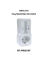
Watts PR03 RF 230 Installation guide

Type
Installation guide

The Watts PR03 RF 230 is a wireless plug receiver that can be controlled remotely using a compatible thermostat or central unit. It features a power button for manual control, an LED indicator to display the device status, and a reset button for factory reset. With a maximum load capacity of 10A or 2300W, it can be used to control various electrical appliances, including radiators, lights, and other devices.

The Watts PR03 RF 230 is a wireless plug receiver that can be controlled remotely using a compatible thermostat or central unit. It features a power button for manual control, an LED indicator to display the device status, and a reset button for factory reset. With a maximum load capacity of 10A or 2300W, it can be used to control various electrical appliances, including radiators, lights, and other devices.

PR03 RF 230
Wireless plug receiver - Vision® Smart Plug
Vision® Wireless
Installation manual
wattswater.eu
EN
FR
User guide
Manuel d’utilisation
2
EN
Table of content
1. General information ............................................................................................................................................................................................................................................................................................................................. 3
2. Presentation.............................................................................................................................................................................................................................................................................................................................................................. 4
3. Box content ............................................................................................................................................................................................................................................................................................................................................................... 4
4. Product description ............................................................................................................................................................................................................................................................................................................................. 5
5. Installation ..................................................................................................................................................................................................................................................................................................................................................................... 5
6. Types of Installation ............................................................................................................................................................................................................................................................................................................................ 6
7. Technical characteristics ...................................................................................................................................................................................................................................................................................................... 7
8. Dimensions .................................................................................................................................................................................................................................................................................................................................................................. 7
3
EN
This product should be installed preferably by a qualified
professional. Subject to observation of the above terms, the
manufacturer shall assume the liability for the equipment as
provided by legal stipulations.
Do not exceed the maximum power rating 10A or 2300W.
All instructions in this Installation & Operation manual
should be observed when working with the smart plug.
Failures due to improper installation, improper use or poor
maintenance are voiding manufacturer liability.
This product is for indoor use only. Do not expose to
water, dust, chemicals and moisture. Keep away from heat
sources and direct sunlight.
Children should use this device only under the supervision
of a responsible adult to control appliances safely.
Do not drop or subject the device to undue shock.
Do not attempt to service or disassemble. Any attempt
to repair voids the responsibility and the obligation to
guarantee and replacement from the manufacturer.
If you experience problems with the device, discontinue
use, unplug the device from the wall outlet and contact
your Customer Services for assistance
Unplug this device during lightning storms or when unused
for long periods of time.
2012/19/EU (WEEE directive): Products marked with this
symbol cannot be disposed of as unsorted municipal
waste in the European Union. For proper recycling, return
this product to your local supplier upon the purchase of
equivalent new equipment, or dispose of it at designated
collection points. For more information see: www.
recyclethis.info
Application
The smart plug receiver have been designed for use in
residential rooms, office spaces and industrial facilities.
Verify that the installation complies with existing regulations
before operation to ensure proper use of the installation.
Please refer to « Quick Installation Guide » for smart
plug receiver installation
Safety warnings and operating instructions
1. General information
https://wattswater.eu/catalog/regulation-and-control/
watts-vision-smart-home/smart-plug-PR03-RF/
4
EN
3. Box contents
1 x 1 x
Vision® Smart Plug Quick installation guide
2. Presentation
Vision® Smart Plug is compatible with Watts Vision® system.
Wireless bidirectional communication 868,3 MHz.
Specially designed to control electrical radiator regulation in combination
with a Vision® wireless thermostat BT-D03 RF type.
This couple (Thermostat with smart Plug) can also be managed by a
Central unit BT-CT02 RF or BT-CT03 RF to have full control of your heating
installation from one point.
Possibility to use the Vision® Smart Plug as light or On/Off control device in
combination with a Central unit BT-CT02 RF or BT-CT03 RF.
Full remotely control with the WATTS Vision® Mobile application.
5
EN
4. Product description
5. Installation
Install and connect the Vision® Smart Plug respecting the fozllowing guidelines to guarantee an optimal reception:
The Vision® Smart Plug must be mounted at a minimum distance of 50cm of all others wireless materials like GSM,
Wi-Fi router.
• Wiring work related to the Vision® Smart Plug must be carried out only when de-energized.
• Connect your Vision® Smart Plug to the power supply.
Depending on your installation, an installation of a Watts RF repeater paired to the central unit must be required to ensure
a correct RF signal transmission
• Turn ON/OFF the socket 1 sec -> LED Blue / Ø
• Device Paring 2 sec -> LED flashes Red/Green
• Factory reset 10 sec -> LED flashes Green
LED status
• Flashing Red /Green: Pairing process initiated
• Flashing : • One Flash red/green/blue: initialization, rebooting
• Green flashing no network connection (2 hours loss) or sensor loss
• Blue flashing over temperature detected
Note : The led is switched off between 8pm and 8am if the plug is associated with a Vision® Centrale Unit
or a Vision® wireless programmable thermostats.
LED
POWER BUTTON
OUTLET
INLET
6
EN
6. Types of installation
Option 1: Vision® Smart Plug + RF thermostat for heating regulation.
1. Switch on the Smart Plug.
2. Press the Button during 3 sec to switch to RF Init.
3. The LED should be flashing Red /Green indicating that the plug is now in radio configuration mode waiting for a
thermostat configuration address.
4. Please refer to the thermostat leaflet for enter the thermostat in “RF Init” mode.
5. Then The Vision® Smart Plug LED must be switched OFF and the thermostat should exit the RF init mode
to indicate correct paring between both elements. You can pair several Vision® Smart Plug to the same RF
thermostats.
Option 2: Vision® Smart Plug + RF Thermostat + RF Central unit BT-CT02 RF or BT-CT03 RF for heating regulation
and remote control with mobile APP.
1. First step is to pair the RF thermostat to the Central unit.
2. Press the RF button on the Smart Plug during 3sec.
3. The RF LED should be flashing Red /Green indicating that the Smart Plug is now in radio configuration mode waiting
for a central configuration address.
4. Please refer to the leaflet of the Central unit for more explanation about the pairing mode “RF Init. You must pair the
Smart Plug as a heating device in the Central unit.
5. The RF LED on the Smart Plug will switch OFF and the Central will show a message to indicate correct pairing
between both elements. You can pair several receivers in the same room.
Option 3: Vision® Smart Plug + RF Central unit BT-CT02 RF or BT-CT03 RF for ON/OFF devices or light control, timer
mode and remote control with mobile APP.
1. Press the Button 3sec to switch the Smart Plug in RF Init mode.
2. The LED should be flashing Red /Green indicating that the Smart Plug is now in radio configuration mode waiting for
a central configuration address.
3. Please refer to the leaflet of the Central unit for more explanation about the pairing mode “RF Init. You must pair the
Receiver as an ON/OFF plug or a light in the Central unit.
4. The LED on the Smart Plug will switch OFF and the Central will show a message to indicate correct pairing between
both elements. You can pair several receivers in the same room. Receiver will work in Timer mode; you have the
possibility to create a weekly program for ON/OFF period.
or ON/OFF
Note for installations 2 and 3:
You can pair several receivers. Pay attention! Before linking a new receiver with the Central unit, you have to
reset the receiver imperatively.
• In case of a thermostat in RF Alarm, the Smart Plug stops heating.
7
EN
7. Compatible thermostats
Digital Wireless Heat & CoolAnalogic Wireless Heat & Cool Programmable Wireless Heat & Cool
8. Technical characteristics
9. Dimensions
49 mm
49 mm 83 mm
Environment:
Operating temperature
Shipping and storage temperature
Thermal safety temperature (relay opening)
0°C to 40°C
-10°C to +50°C
When > 85°C (back to standard mode when < 65°C)
Power supply 230VAC 50Hz with European plug socket
Electrical protection Cat. II - IP20
Output
Maximum Résistive Load Relay
Relay 10 A Max
230V 50Hz
Radio Frequency & RF
Receiving distance
868,3 MHz < 10mW (Bidirectional communication)
30m in residential environment (100m in open field)
EU declaration of conformity
Hereby, Watts Electronics declares that the
equipment is in compliance with the relevant
Community harmonization legislation
Low voltage (LVD) - Directive 2014/35/EU
Electromagnetic compatibility (EMC) - Directive 2014/30/EU
Radio equipment - Directive 2014/53/EU
Restriction of the use of certain hazardous substances (RoHS)
- Directive 2011/65/EU
The full text of the EU declaration of conformity is available on
wattswater.eu
Product is in compliance with
Classication
Contribution
UE 811/2013 and 2010/30/UE
IV
2%
8
FR
Table des matières
1. Généralités ................................................................................................................................................................................................................................................................................................................................................................... 9
2. Présentation.........................................................................................................................................................................................................................................................................................................................................................10
3. Contenu de la boîte ........................................................................................................................................................................................................................................................................................................................ 10
4. Description du produit............................................................................................................................................................................................................................................................................................................11
5. Installation ................................................................................................................................................................................................................................................................................................................................................................11
6. Types d’installation ..........................................................................................................................................................................................................................................................................................................................12
7. Caractéristiques techniques .................................................................................................................................................................................................................................................................................. 13
8. Dimensions ............................................................................................................................................................................................................................................................................................................................................................. 13
9
FR
Ce produit doit être installé de préférence par un
technicien agréé. Sous réserve du respect des conditions
susmentionnées, le fabricant assume la responsabilité de
l’équipement conformément aux dispositions légales.
Ne pas dépasser la puissance nominale maximale 10A ou
2300W.
Toutes les instructions figurant dans le manuel d’installation
et d’utilisation doivent être respectées lors des interventions
sur le thermostat. Toute installation, utilisation ou entretien
incorrect annule la responsabilité du fabricant.
Ce produit est destiné à une utilisation en intérieur
uniquement. Ne pas exposer à l’eau, à la poussière, aux
produits chimiques et à l’humidité. Tenir à l’écart des
sources de chaleur et de la lumière directe du soleil.
Les enfants doivent utiliser cet appareil uniquement sous
la surveillance d’un adulte responsable pour contrôler les
appareils en toute sécurité.
Ne pas laissez tomber ou ne soumettez pas l’appareil à
des chocs excessifs.
N’essayez pas de réparer ou de démonter. Toute tentative
de réparation annule la responsabilité et l’obligation de
garantie et de remplacement du fabricant.
Si vous rencontrez des problèmes avec l’appareil, arrêtez
de l’utiliser, débranchez l’appareil de la prise murale et
contactez votre service clientèle pour obtenir de l’aide.
Débranchez cet appareil pendant les orages ou lorsqu’il
n’est pas utilisé pendant de longues périodes.
2012/19/UE (directive DEEE) : les produits portant ce
symbole ne peuvent pas être mis au rebut en dehors d’un
centre de tri sélectif dans l’Union européenne. Pour un
recyclage correct, renvoyer ce produit au fournisseur local
contre l’achat d’un appareil neuf équivalent, ou le remettre
à un point de collecte prévu à cet effet. Pour de plus
amples informations, consulter le site : www.recyclethis.info
Application
La prise intelligente Smart Plug a été conçue pour
être utilisée dans les habitations, les bureaux et les
sites industriels. Vérifier que l’installation est
conforme à la législation en vigueur avant la mise
en service pour garantir son utilisation adéquate.
Consulter le « Guide d’installation rapide » pour
obtenir des informations sur l’installation de la prise
intelligente Smart plug.
Avertissements de sécurité et consignes d’utilisation
1. Généralités
https://wattswater.eu/catalog/regulation-and-control/
watts-vision-smart-home/smart-plug-PR03-RF/
10
FR
3. Contenu de la boîte
1 x 1 x
Vision® Smart Plug Guide d’installation rapide
2. Présentation
Vision® Smart Plug est compatible avec le système Watts Vision®.
Communication bidirectionnelle sans fil 868,3 MHz.
Spécialement conçu pour contrôler la régulation électrique des radiateurs
en combinaison avec un thermostat sans fil Vision® type BT-D03 RF.
Ce ensemble (Thermostat avec la prise intelligente Smart Plug) peut
également être géré par une unité centrale BT-CT02 RF ou BT-CT03 RF
pour avoir le contrôle total de votre installation de chauffage à partir d’un
point.
Possibilité d’utiliser la prise intelligente Vision® Smart Plug comme dispositif
de contrôle de la lumière ou marche/arrêt en combinaison avec une unité
centrale BT-CT02 RF ou BT-CT03 RF.
Contrôle à distance complet avec l’application mobile WATTS Vision®.
11
FR
LED
4. Description du produit
5. Installation
Installez et connectez la Vision® Smart Plug en respectant les consignes suivantes pour garantir une réception optimale :
La prise intelligente Vision® Smart Plug doit être montée à une distance minimale de 50 cm de tout autre matériel sans fil
comme un smartphone GSM, routeur Wi-Fi.
• Les travaux de câblage liés à la Vision® Smart Plug doivent être effectués uniquement lorsqu’ils sont hors tension.
• Connectez votre Vision® Smart Plug à l’alimentation.
Selon votre installation, l’installation d’un répéteur RF Watts couplé à l’unité centrale doit être nécessaire pour assurer une
bonne transmission du signal RF.
BOUTON D’ALIMENTATION
• Allumer/éteindre la prise 1 sec -> LED Bleu / Ø
• Appariement de l’appareil 2 sec -> LED clignote en rouge/vert
• Réinitialisation d’usine 10 sec -> LED clignote en vert
État de la LED
• Rouge/vert clignotant : processus d’appairage lancé
• Clignotement : • Un Flash rouge/vert/bleu : initialisation, redémarrage
• Vert clignotant pas de connexion réseau (perte de 2 heures) ou perte de capteur
• Bleu clignotant au-dessus de la température détectée
Note : La led s’éteint entre 20h et 8h si la prise est associée à une unité Centrale Vision® ou à un
thermostat programmable sans fil Vision®.
SORTIE
ENTRÉE
12
FR
6. Types d’installation
Option 1: Vision® Smart Plug + Thermostat RF pour la régulation du chauffage.
1. Allumez la prise intelligente Smart Plug.
2. Appuyez sur le bouton RF de la Smart Plug pendant 3 secondes pour initialiser le mode d’appairage “RF Init.
3. La LED doit clignoter en rouge/vert indiquant que la prise est maintenant en mode de configuration radio en attente
d’une adresse de configuration du thermostat.
4. Veuillez vous référer à la notice du thermostat pour passer en mode d’initialisation “RF” du thermostat.
5. Ensuite, la LED de la Vision® Smart Plug doit être éteinte et le thermostat doit quitter le mode d’initialisation “RF”
pour indiquer un jumelage correct entre les deux appareils. Vous pouvez jumeler plusieurs Vision® Smart Plug aux
mêmes thermostats RF.
Option 2: Vision® Smart Plug + Thermostat RF + Unité centrale Vision® type BT-CT02 RF ou BT-CT03 RF pour la
régulation du chauffage et contrôle sans fil avec l’application mobile.
1. La première étape consiste à coupler le thermostat RF à l’unité centrale.
2. Appuyez sur le bouton RF de la Smart Plug pendant 3 secondes pour initialiser le mode d’appairage “RF Init.
3. La LED RF doit clignoter en rouge/vert indiquant que la Smart Plug est maintenant en mode de configuration radio
en attente d’une adresse de configuration de l’unité centrale.
4. Veuillez vous référer à la notice de l’unité centrale pour plus d’explications sur le mode d’appairage “RF Init.
Vous devez jumeler la Smart Plug en tant qu’appareil de chauffage dans l’unité centrale.
5. La LED RF sur la Smart Plug s’éteindra et l’unité centrale affichera un message pour indiquer l’appariement correct
entre les deux appareils. Vous pouvez jumeler plusieurs Smart Plug dans la même pièce.
Option 3: Vision® Smart Plug + Unité centrale Vision® type BT-CT02 RF ou BT-CT03 RF pour appareils ON/OFF ou
contrôle de la lumre, mode minuterie et contrôle sans fil avec l’application mobile.
1. Appuyez sur le bouton RF de la Smart Plug pendant 3 secondes pour initialiser le mode d’appairage “RF Init.
2. La LED RF doit clignoter en rouge/vert indiquant que la Smart Plug est maintenant en mode de configuration radio
en attente d’une adresse de configuration de l’unité centrale.
3. Veuillez vous référer à la notice de l’unité centrale pour plus d’explications sur le mode d’appairage “RF Init.
Vous devez appairer la Smart Plug comme une prise ON/OFF ou un appareil d’éclairage dans l’unité centrale.
4. La LED RF sur la Smart Plug séteindra et l’unité centrale affichera un message pour indiquer l’appariement correct
entre les deux appareils. Vous pouvez jumeler plusieurs Smart Plug dans la même pce. La Smart Plug fonctionnera
en mode minuterie ; vous avez la possibilité de créer un programme hebdomadaire pour la période ON/OFF.
Remarque pour les installations 2 et 3 :
Vous pouvez jumeler plusieurs récepteurs. Faites attention! Avant d’associer une nouvelle Smart Plug à l’unité
centrale, vous devez impérativement réinitialiser la Smart Plug.
• Dans le cas d’un thermostat en Alarme RF, la Smart Plug arrête de chauffer.
ou ON/OFF
13
FR
7. Thermostats Compatibles
9. Dimensions
Analogique sans fil Heat & Cool Digital sans fil Heat & Cool Programmable sans fil Heat & Cool
Environnement :
Température de service
Température d’expédition et de stockage
Température de sécurité thermique (ouverture relais)
0°C à 40°C
-10°C à +50°C
Quand > 85°C (retour au mode standard quand < 65°C)
Tension électrique 230VAC 50Hz avec prise de courant européenne
Protection électrique Cat. II - IP20
Sortie
Relais de charge résistive maximale
Relais 10 A Max
230V 50Hz
Radiofréquence et RF &
Distance de réception RF
868,3 MHz < 10mW (Communication bidirectionnelle)
30m en milieu résidentiel (100m en champ libre)
Déclaration de conformité UE
Par la présente, Watts Electronics déclare que
l’équipement est conforme à la législation
communautaire d’harmonisation pertinente
Directive basse tension (LVD) 2014/35/EU
Directive compatibilité électromagnétique (EMC) 2014/30/EU
Directive sur les équipements radio 2014/53/EU
Restriction de l’utilisation de certaines substances
dangereuses (RoHS) - Directive 2011/65/EU
Le texte intégral de la déclaration UE de conformité
est disponible sur wattswater.eu
Produit conforme à
Classication
Contribution
UE 811/2013 et 2010/30/UE
IV
2%
8. Caractéristiques techniques
49 mm
49 mm 83 mm
Watts Electronics S.A.S
B.P. N°10 - Z.A. des Tourettes, 43800 ROSIERES, France,
T: +33(0) 471 57 40 49, F: +33(0) 471 57 40 90,
www.wattswater.eu
Watts contacts in Europe: https://wattswater.eu/watts/contacts/
© 2023 Watts
BT-PR03RF-IOM-FR-W-ML-07-23
  • Page 1 1
  • Page 2 2
  • Page 3 3
  • Page 4 4
  • Page 5 5
  • Page 6 6
  • Page 7 7
  • Page 8 8
  • Page 9 9
  • Page 10 10
  • Page 11 11
  • Page 12 12
  • Page 13 13
  • Page 14 14

Watts PR03 RF 230 Installation guide

Type
Installation guide

The Watts PR03 RF 230 is a wireless plug receiver that can be controlled remotely using a compatible thermostat or central unit. It features a power button for manual control, an LED indicator to display the device status, and a reset button for factory reset. With a maximum load capacity of 10A or 2300W, it can be used to control various electrical appliances, including radiators, lights, and other devices.

Ask a question and I''ll find the answer in the document

Finding information in a document is now easier with AI

in other languages