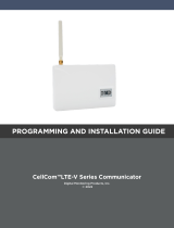
Topkodas GTCOM2 User guide

Category
Touch screen monitors
Type
User guide

Topkodas GTCOM2 is a GSM communicator that acts as a bridge between your primary alarm system and the outside world, enabling remote control, monitoring, and alerts via SMS or the SeraNova mobile app. With built-in LEDs for status indication, you can easily check the device's condition. The module supports Contact ID data transfer in DTMF tones, allowing seamless integration with compatible alarm panels. Stay informed and take control of your security system with ease using the GTCOM2.

Topkodas GTCOM2 is a GSM communicator that acts as a bridge between your primary alarm system and the outside world, enabling remote control, monitoring, and alerts via SMS or the SeraNova mobile app. With built-in LEDs for status indication, you can easily check the device's condition. The module supports Contact ID data transfer in DTMF tones, allowing seamless integration with compatible alarm panels. Stay informed and take control of your security system with ease using the GTCOM2.

Experts of automation, security product development
GTCOM2
GSM Communicator
Contact ID to SMS converter
Stay informed, take control
Quick setup guide
UAB “Topkodas”, JSC
Mobile: +370 655 58449, E-mail: info@topkodas.lt
http://www.topkodas.lt
FREE SeraNova web app: https://seranova.eu/login
FREE SeraNova Mobile app:
https://play.google.com/store/apps/details?id=com.seranova.cl
oud
When primary alarm panel is triggered, it signals the alarm
communicator which in turn notifies a CMS. Integrated SIA IP
DC-09 protocol.
The module receives Contact ID DTMF codes from the dial-up
communicator of security control panel, converts them into
readable texts and sends SMS message to the mobile
phone of a user.
It is possible to check the status, control the panel via mobile
app.
Selectable 2G, 3G or 4G LTE modem. App notifications,
Call alarms, SMS alarms, Events log list.
Configuration templates and remote configuration
possibility. Easy SIM card, USB access. No need to open
enclosure!
REQUIREMENTS OF THE SECURITY CONTROL PANEL
The security control panel should meet the following
requirements:
1. To support Ademco Contact ID protocol according to SIA DC-
05 standard.
2. To support dialing in DTMF tones.
3. To support Contact ID data transfer in DTMF tones.
4. It is recommended for the control panel to support automatic
Contact ID codes.
MEANING OF LEDS AND CONTACTS
Name
Indication
variations
Meaning
REG
(yellow)
built-in
LED
Lights
continuously
Modem has been registered
to the network
Flashes,
remains lit for
50ms, turns off
for 300ms
Modem is being registered to
the GSM network.
Blinking fast,
remains lit for
50ms turns off
for 50ms
PIN code of SIM card error.
PIN code request should be
removed
Off
Modem failed to register to
the network.
DATA
(red)
built-in
LED
Lights
continuously
The memory of the module
contains unsent reports to
the user or to the server.
Off
All reports has been send.
PWR
(green)
built-in
LED
Watchdog heart
beat blinking,
remains lit for
50ms, and turns
off after
1000ms.
The module is functioning.
Off
The module is out of order or
no voltage
LINE
(blue)
Lights
continuously
The security control panel
has picked up a handset Off-
hook
OFF
The security control panel
has not picked up a handset
On-hook
DTMF
Blinking 5-10ms
DTMF tones are receiving
from the control panel
Blinking 1s
DATA OK. Data received
correctly.
LINE (blue) LED lights continuously, when central panel OFF
HOOK DTMF LED is blinking (5-10ms). When DTMF LED
lights for 1s, data received correctly.
FIRST STEPS TO PREPARE GTCOM2 MODULE & SERA2
SOFTWARE
Preparation procedure of the module GTCOM2.
1. Connect the GSM antenna to the antenna connector.
2. Insert the SIM card in the SIM card holder.
Ensure that PIN request function is disabled.
Ensure that mobile internet service (mobile data) is enabled if
mobile app or IP connection with CMS will be used.
To avoid entering the PIN code in Sera2 software, insert the SIM
card into your mobile phone and turn off the PIN request
function.
3. Connect the module to the primary alarm panel.
4. Connect the module to the computer via mini USB cable
Install configuration software SERA2
Download SERA2 from www.topkodas.lt , install and open it.
If you want to edit existing configuration,
You have to read it (press “Read” in the command line). Edit
settings. Write edited configuration (press Write” in the
command line)
COMMUNICATOR WIRING METHODS
The alarm panel is linked up with GTCOM2 communicator via
the RING and TIP terminals simulating the connectivity of the
PSTN line.
RING/TIP interface Retrieves Ademco Contact ID data from
the alarm panel, converts it into user-understandable text and
delivers to up to 8 listed users by SMS text message.
The outputs can also be used for arming/ disarming by
connecting an output to one of the alarm panel’s zones pre-
configured as a keyswitch.
If the control panel status changes from ARM to DISARM, the
status of GTCOM2 changes from ARM to DISARM also
If the siren is triggered, the SMS will be send to the user’s
mobile followed by a call
GTCOM2 could be used for all control panel control, gate
control. The second keyswitch can be used to stay ARM.
The first keyswitch could be used for arm the first partition and
the second keyswitch can be used for arm the second partition
Figure 2Communicator
wiring diagram
Figure 1 ARM/ DISARM the panel
via keyswitch zone
ALARM PANEL & GTCOM2 SYNCHRONIZATION
Control primary panel via short call, app, SMS
Control primary panel from GTCOM2 and see the status in
app
Control primary panel from GTCOM2 and see the status in app
Receive status SMS.
See the same status in keypad
Control GTCOM2 from primary panel and see the status in
keypad.
Control GTCOM2 from primary alarm panel and see the status
in keypad
The same status in mobile app and SMS
How to set primary panel?
Configuration of the panel PSTN communicator should be the
similar as event transmission to the monitoring station receiver
in CONTACT ID DTMF protocol. Practically the module can
work with any central panel which has PSTN communicator and
meets Ademco Contact ID data format according to SIA SIA DC-
05 standard. Also Central panel must support phone number
dialing using DTMF tones.
Panel’s PSTN communication settings:
Set communication enabled
Set communicator account number 4 digits. E.g. “1234
Set communications Telephone. Enter the monitoring station
receiver’s telephone number (you can use any number longer
than 2 digits. The GTCOM2 pick up and answer when the panel
calls to any phone number). Telephone number e.g. “1234”.
Set communication dialing options to [DTMF Dialing]*
Set Communications protocol to [DTMF Contact ID]*
If panel has such option set [Contact ID Automatic Reporting
Codes]
Enable PSTN communication events upon your needs
Open/Close/Alarm/Restore/Maintenance/Test
Panel’s settings for two ways ARM/DISARM
synchronization***.
Set Panel PGM to monitoring ARM status in level (steady) Mode
Activation event:[ ARM Area1 ]
Deactivation Event : [ DISARM Area1 ]
Mode: [Steady]
NO/NC depending of GTalarm2 input keyswitch settings.
In our example set to [NO]
Set Panel Keyswitch to Momentary (Pulse) Mode
Zone Type : [Keyswitch Momentary] (Pulse)
Area Assigment: [Area 1] (Set AREA you want to control)
Keyswitch Action: [ARM/DISARM]
*Communicator's data package protocol SIA Ademco
CONTACT ID is being supported (according to SIA DC-05
standard)
*Telephone number and data transfer format DTMF (tone)
*** Two ways ARM/DISARM synchronization means USER able
to control panel via panel’s keyboard as well as remotely form
GTCOM2 APP/WEB/SMS/iButton/RFID/Call. This means that
the GTCOM2 APP will show the same system status as
keyboard of security panel.
HOW TO SET GTCOM2 & PRIMARY PANEL
SYNCHRONIZATION By Panel’s PGM?
Go to SERA2> System Options> General System Options
Set App ARM/ DISARM Synchr mode to “By Panel PGM
Set GTCOM2 keyswitch zone
Go to SERA2> Inputs/ Burglar Alarm Zones and set:
Keyswitch Zone Mode : [Level] (Steady)
Definition: [keyswitch ARM/DISARM]
Type: [NC]
Press “Write”
Set module PGM action on ARM/DISARM command from
APP/CALL/SMS/iButon/RFID
Go to SERA2> Outputs (PGM).
Out Definition: [Activate by ARM/DISARM Command]
No: [1] (this is partition number )
Mode: [Pulse]
Timer: [2s] (this is PGM pulse time on ARM/DISARM
command)
HOW TO SET GTCOM2 & PRIMARY PANEL
SYNCHRONIZATION By Panel’s Events
A) do not need one wire from GTCOM2 input to Panel’s PGM
Go to SERA2> System Options> General System Options
Set App ARM/ DISARM Synchr mode to “By Panel Events”
Set module PGM action on ARM/DISARM command from
APP/CALL/SMS/iButon
Go to SERA2> Outputs (PGM)
Out Definition: [Activate by ARM/DISARM Command]
No: [1] (this is partition number)
Mode: [Pulse]
Timer: [2s] (this is PGM pulse time on ARM/DISARM
command)
B)
Need to connect: TIP/RING
GTCOM PGM -> Panel Keyswitch (Pulse mode)
GTCOM Keyswitch <- Panel PGM (Level Mode)
Go to SERA2> System Options> General System Options
Set App ARM/ DISARM Synchr mode to “By Panel Events”
Set GTCOM2 keyswitch zone
Go to SERA2> Inputs> Burglar Alarm Zones and set:
Keyswitch Zone Mode : [Level] (Steady)
Definition: [keyswitch ARM/DISARM]
Type: [NC]
Press “Write”
Set module PGM action on ARM/DISARM command from
APP/CALL/SMS/iButon
Out Definition: [Activate by ARM/DISARM Command]
No: [1] (this is partition number )
Mode: [Pulse]
Timer: [2s] (this is PGM pulse time on ARM/DISARM
command)
Install Android app.
1.Scan QR code with your Android Phone:
Or go to https://play.google.com
And find SeraNova app
Or use web verion at:
https://seranova.eu/login
2. Log in with your user name and password or register and
create a new account. 3. If You don’t know IMEI Send IMEI
requested SMS command to the number of the SIM card
inserted into the controller. IMEI request SMS: INST000000 100
1 Or got to SERA2> System Options> System Info 4. Go to
SYSTEMS, Choose Add new system and enter the controller
Unique ID (IMEI) number. IMPORTANT: When adding the
communicator to SeraNova app: 1. The Sera Cloud service
must be turned on. 2. The power supply must be turned on. 3.
Must be registered in to network. Default App Key: 123456.
„User Code to Control System“ must be the same as "Keypad
code" in the Sera2> "User/ access control" Default 123456
ARM/ DISARM with SMS
User phone number must be the SERA2> Users/ Access control list
Send SMS message to the module: USER123456˽030˽ST
USER command from user commands list
123456 user’s password (default)
˽ - Space character
030- command code
˽ - Space character
ST - Configuration array
Change security system’s mode (ARM/DISARM/STAY/SLEEP)
030= command code (Change security system’s mode
(ARM/DISARM/STAY/SLEEP)
ST = Security system mode 0-DISARM, 1-ARM, 2-STAY, 3-
SLEEP
Enter user phone number in the Sera2> Users/ Access control
list
How to test GTCOM2 & Primary Panel synchronization?
Go to SERA2> RT Testing & Monitoring> Hardware
Press “Start Monitoring” button
Press I/O1 On/Off button
See in Inputs (ADC values) Should change 1 > 0 or 0>1
Status of the primary panel should change
Go to SERA2> RT Testing & Monitoring> Security Alarm
Panel/ Access
The status of GTCOM2 module should change
You will see the same process in your smart phone. In
mobile app.
  • Page 1 1
  • Page 2 2

Topkodas GTCOM2 User guide

Category
Touch screen monitors
Type
User guide

Topkodas GTCOM2 is a GSM communicator that acts as a bridge between your primary alarm system and the outside world, enabling remote control, monitoring, and alerts via SMS or the SeraNova mobile app. With built-in LEDs for status indication, you can easily check the device's condition. The module supports Contact ID data transfer in DTMF tones, allowing seamless integration with compatible alarm panels. Stay informed and take control of your security system with ease using the GTCOM2.

Ask a question and I''ll find the answer in the document

Finding information in a document is now easier with AI