Ruskin CFD7T User manual

Type
User manual

Ruskin CFD7T is a ceiling damper designed to function as a heat barrier in HVAC openings penetrating ceilings constructed from wood trusses. It has been UL tested to provide protection in various ceiling designs without the added requirement for insulated boots, boxes, or plenums. The damper can be used with or without a plenum box and supports various duct types, including flex duct, steel duct, and ductboard. Installation is versatile, with options for support angles or a 2" x 4" wood stud.

Ruskin CFD7T is a ceiling damper designed to function as a heat barrier in HVAC openings penetrating ceilings constructed from wood trusses. It has been UL tested to provide protection in various ceiling designs without the added requirement for insulated boots, boxes, or plenums. The damper can be used with or without a plenum box and supports various duct types, including flex duct, steel duct, and ductboard. Installation is versatile, with options for support angles or a 2" x 4" wood stud.

II-CFD7T-0621/Replace II-CFD7T-613 ALL STATED SPECIFICATIONS ARE SUBJECT TO CHANGE WITHOUT NOTICE OR OBLIGATION. © Ruskin June 2021
Page 1
Support Angle to Damper: minimum of two #8 sheet metal screws, 3/16” (4)
tubular rivets, tack or spot-welds per angle.
Support Angle to Truss: minimum of #8 x 3/4” long screw or #6 penny nail 1” long
(25).
Grill/Diffuser frame to damper: minimum of two #8 x 1 1/4” (32) min. screws
through the ceiling material and into the plaster flange or sub-frame.
Retaining Angle to Plaster Flange or Sub-frame: minimum of #8 x 1 1/4” (32) min.
screws through the ceiling material and into the plaster flange or sub-frame. One
screw per side required on units 10” (254) long and under, and two screws per side
on units above 10” (254) long. Round units maximum of 3 screws required.
Make sure fasteners do not interfere with the damper operation.
CFD7T - No Plenum Box
CFD7T-IB6 - R6 Duct Lined Stl. Plenum Box (Max 1 sq. Ft.)
CFD7T-SB - Steel Plenum Box
CFD7T-90-BT - 90 degree Boot
CFD7T-END-BT - End Boot
CFD7T-ST-BT - Stright Boot
CFD7T-R6-DB - R6 Duct Board
Model CFD7T is designed to function as a heat barrier in HVAC openings penetrating
ceilings constructed from wood trusses. The CFD7T has been UL tested to provide
protection in UL ceiling design L528, L546, L558, L574, L585, L586, L592, P533, P538,
P545, P548, P580 and H502. without the added requirement for insulated boots, boxes
or plenums.
The ceiling damper and associated components (air devices, duct, duct drop, etc.)
must be constructed of steel. The grille/diffuser frame shall be minimum of 26
gauge (0.55) steel. Nonferrous air devices or through ceiling membrane penetration
a steel plaster flange is required. Flexible duct must be class 0 or 1 type and bear the
UL listing mark and shall be attached to the plenum collar with steel clamps, plastic
straps, or minimum 18 gauge steel wire. Fiberglass ductboard plenum box shall be
UL 181 listed. Field supplied plenum boxes not to exceed 10 Ib. The installation and air
device shown in these instructions illustrate general arrangements only. Installation
must incorporate applicable requirements for the specific Floor/ceiling or Roof/ceiling
construction in the UL Fire Resistance Directory.
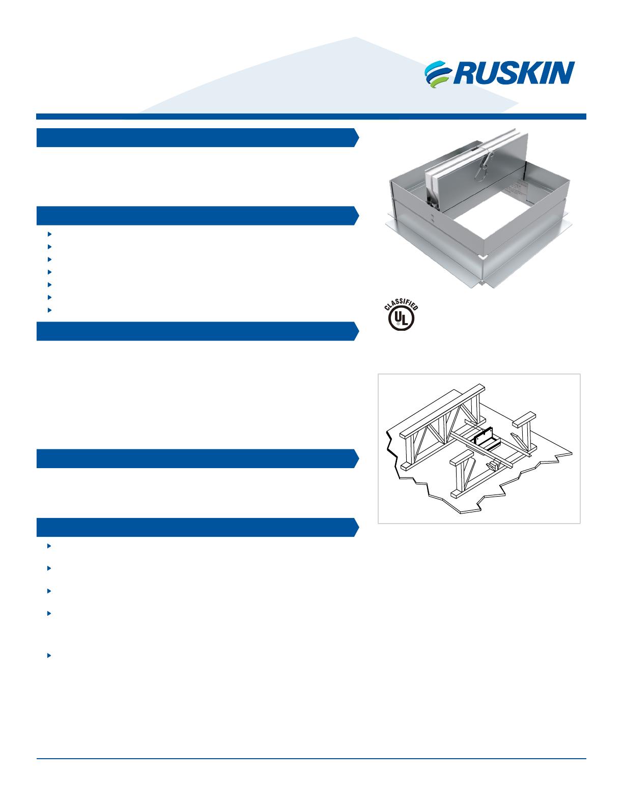
Ceiling penetrations should be located between adjacent truss and RC or Furring
channels. If required, a maximum of one RC or Furring channel may be cut or notched
to enable proper damper location. The clearance between the damper assembly and
the cutout in the ceiling material shall be a maximum of 1/8” (3) on any side.
NOTE:
- Dimensions shown in parentheses ( ) indicate millimeters.
APPLICATION
SYSTEM COMPONENTS
CEILING PENETRATIONS
DAMPER MODELS
UL CLASSIFIED
UL555C Listing R8039
California State Fire Marshal Listing No. 3226-0245:0123
AUTHORITY IN AIR CONTROL
CFD7T SERIES
Installation Instructions
Ceiling Dampers For Wood Truss Assemblies
UL555C 1 Hour Rated
SEE COMPLETE
MARKING ON PRODUCT
II-CFD7T-0621/Replace II-CFD7T-613 ALL STATED SPECIFICATIONS ARE SUBJECT TO CHANGE WITHOUT NOTICE OR OBLIGATION. © Ruskin June 2021
Page 2
Damper support may be achieved by suspending the damper from
support angles Item #5 or 2” x 4” (51 x 102) wood stud fastened to
adjacent trusses and the damper suspended with four 18 swg steel wire
or 3/4” x 3/4” x 26ga. (16 x 16 x .55) angle tabs spaced evenly around
the damper.
Cut the vertical leg of the support angle and fold up 90° both ends. Attach
support angle to the inside leg of the truss with minimum of 2 - #8 screws
or nails per angle.
CFD7T UNDUCTED OR FLEX DUCT
ITEM DESCRIPTION
1Wood Truss Assembly (Refer to UL Fire Resistance Directory)
2RC Channel or Furring Channel or Steel Framing Members
3UL rated gypsum wallboard (See UL design No.)
4Ceiling Radiation Damper
53/4” x 3/4” x 16ga. (19 x 19 x 1.61) or 11/2” x 11/2” x 22 ga.
(38 x 38 x .85) Support Angle (2 sides) See Note 1
ITEM DESCRIPTION
6Steel Frame Grille Diffuser
71” x 1” x 22 ga. (25 x 25 x .85) Retaining Angle on all 4 sides
8Sub-frame or plaster flange
9Insulation (optional)
Alternate Support Angle InstallationAlternate Damper Support
Through Ceiling Membrane PenetrationWith Grille Diffuser
14
5
9
6
8
3
2
14
5
9
7
8
3
2
8
2
3
4
5
11
2
3
5
II-CFD7T-0621/Replace II-CFD7T-613 ALL STATED SPECIFICATIONS ARE SUBJECT TO CHANGE WITHOUT NOTICE OR OBLIGATION. © Ruskin June 2021
Page 3
Damper support may be achieved by suspending the damper from
support angles Item #5 or 2” x 4” (51 x 102) wood stud fastened to
adjacent trusses and the damper suspended with four 18 swg steel wire
or 3/4” x 3/4” x 26ga. (16 x 16 x .55) angle tabs spaced evenly around
the damper.
Cut the vertical leg of the support angle and fold up 90° both ends. Attach
support angle to the inside leg of the truss with minimum of 2 - #8 screws
or nails per angle.
CFD7T-SB, CFD7T-IB6, CFD7T-END-BT, CFD7T-90-BT & CFD7T-ST-BT UNDUCTED OR FLEX DUCT
ITEM DESCRIPTION
1Wood Truss Assembly (Refer to UL Fire Resistance Directory)
2RC Channel or Furring Channel or Steel Framing Members
3UL rated gypsum wallboard (See UL design No.)
4Ceiling Radiation Damper
53/4” x 3/4” x 16ga. (19 x 19 x 1.61) or 11/2” x 11/2” x 22 ga. (38
x 38 x .85) Support Angle (2 sides) See Note 1
6Steel Frame Grille Diffuser
71” x 1” x 22 ga. (25 x 25 x .85) Retaining Angle on all 4 sides
8Sub-frame or plaster flange
9Steel Plenum Box or Boot
10 Duct (optional)
11 Insulation (optional)
Alternate Support Angle InstallationAlternate Damper Support
CFD7T-END-BT, CFD7T-90-BT & CFD7T-ST-BT
CFD7T-SB With Steel Plenum Box
CFD7T-IB6 With Insulated Steel Plenum Box
Through Ceiling Membrane Penetration
3
84
7
10
9
5
2
1
11
33
88
44
66
11 11
10 10
99
5
5
2
2
11
1
2
3
5
8
6
4
9
3
2
1
5
II-CFD7T-0621/Replace II-CFD7T-613 ALL STATED SPECIFICATIONS ARE SUBJECT TO CHANGE WITHOUT NOTICE OR OBLIGATION. © Ruskin June 2021
Page 4
3900 Doctor Greaves Road
Grandview, MO 64030
Website: www.ruskin.com
Phone: (816) 761-7476
AUTHORITY IN AIR CONTROL
CFD7T-R6-DB UNDUCTED OR FLEX DUCT
Cut the vertical leg of the support angle and fold up 90° both ends. Attach
support angle to the inside leg of the truss with minimum of 2 - #8 screws
or nails per angle.
ITEM DESCRIPTION
1Wood Truss Assembly (Refer to UL Fire Resistance Directory)
2RC Channel or Furring Channel or Steel Framing Members
3UL rated gypsum wallboard (See UL design No.)
4Ceiling Radiation Damper
53/4” x 3/4” x 16ga. (19 x 19 x 1.61) or 11/2” x 11/2” x 22 ga. (38
x 38 x .85) Support Angle (2 sides) See Note 1
6Steel Frame Grille Diffuser
71” x 1” x 22 ga. (25 x 25 x .85) Retaining Angle on all 4 sides
8Sub-frame or plaster flange
9Ductboard Plenum Box
10 Duct
11 30 ga. (.25) Steel Sleeve min.
Through Ceiling Membrane Penetration
and Ductboard Plenum Box
Note: See Supplemental Installation Instruction for ductboard Plenum construction.
With Ductboard Plenum Box
33
8
8
44
67
11 11
10 10
99
22
55
11
See Detail A
Damper support may be achieved by suspending the damper from
support angles Item #5 or 2” x 4” (51 x 102) wood stud fastened to
adjacent trusses and the damper suspended with four 18 swg steel wire
or 3/4” x 3/4” x 26ga. (16 x 16 x .55) angle tabs spaced evenly around
the damper.
Alternate Damper Support
Sheet metal Wrapped Ductboard Installation
Detail A
55
11
9
9
4
4
8
11
5
2
386
4
9
1
Alternate Support Angle Installation
1
2
3
5
LINKS TO IMPORTANT DOCUMENTS
Document Title
Quick Select Sheet
Product Data/submittals
  • Page 1 1
  • Page 2 2
  • Page 3 3
  • Page 4 4

Ruskin CFD7T User manual

Type
User manual

Ruskin CFD7T is a ceiling damper designed to function as a heat barrier in HVAC openings penetrating ceilings constructed from wood trusses. It has been UL tested to provide protection in various ceiling designs without the added requirement for insulated boots, boxes, or plenums. The damper can be used with or without a plenum box and supports various duct types, including flex duct, steel duct, and ductboard. Installation is versatile, with options for support angles or a 2" x 4" wood stud.

Ask a question and I''ll find the answer in the document

Finding information in a document is now easier with AI