Page is loading ...

PRODUCT TO THE
DO NOT RETURN
STORE
Missing Parts,
Need Replacements or,
Help with Assembly
PLEASE EMAIL
Customer Service:
Service ezgoal net@.
203 933 4442
West Haven CT 06516,
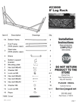
Item # Description Drawings Qty
1 Bottom Bend frame 4
2
Side Bend
(With plastic caps)
4
3
Support Bend
(With plastic caps)
4
4
Bottom tube
(With plastic caps)
2
5
Rectangle
Connector
2
6Brace 7
7 Hex bolt M6x90 8
8 Hex bolt M6x85 4
9 Hex bolt M6x50 14
10 Washer M6 26
11 Lock nut M6 26+1
12 Rope 1
1308 Cover 1
page 1
#23408 instructions
10 10 Rev 300 1-.-
# 23408
8’ wood Rack

Assembly Instructions
Figure 1
Figure 2
STEP 1
Connect 2 Bottom Bend Frame (#1) together
with 1 Rectangle Connector (#5), using 2 Hex
bolts (#9), 2 Washers (#10), and 2 Lock nuts
(#11). See Detail A.
Repeat the same process for the other Bottom
Bend Frames and Connector.
STEP 2
Connect 1 Bottom Tube (#4) to each assembly
(#1&5), using 2 Hex bolts (#8), 2 Washers
(#10), and 2 Lock nuts (#11). See Detail B.
Connect 2 finished assemblies together with 1
Brace (#6) using 2 hex bolts (#9), 2 Washers
(#10), and 2 Lock nuts (#11). See Detail C.
STEP 3
Slide Side Bend (#2) onto Bottom Bend
Frame (#1), secure it with 1 Hex bolt (#9), 1
Washer (#10), and 1 Lock nut (#11) each.
See Detail D.
Connect the top end of Side Bend (#2)
together with one Brace (#6) using 2 hex
bolts (#9), 2 Washers (#10), and 2 Lock
nuts (#11). See Detail E.
Repeat same process for the other side.
Do not tighten at this time.
STEP 4
Connect Support Bend (#3) to the Assembly,
using 8 Hex bolts (#7), 8 Washers (#10), and
8 Lock nuts (#11). See Detail F.
Note: Make sure Brace (#6) go between
Side Bend (#2) and Support Bend (#3).
Tighten all the bolts and nuts used in the
above steps.
Figure 3
5
1
1
5
9
10
11
11
10
1
1
Detail A
A
B
Detail B
Detail C
9
5
6
10
11
8
1
4
4
11
10
4
4
E
D
Detail D
Detail E
2
2
1
10
11
6
9
9
2
1
11
10
9
7
7
2
3
3
6
2
2
6
11
10
3
7
7
7
1
Figure 5
Rope
F
Detail F
STEP 5
Tie Rope(#12) to Side Bends in the front only
(#2),This will make the snow and rain slide off
easy and makes the cover look better on the log
rack.
Figure 4
page 2
#23408 instructions
10 10 Rev 300 1-.-
/


