Page is loading ...

999 3112.5 REV 3 © 2005 Greenlee Textron Inc. 1/05
SPECIFICATIONS AND PARTS
ESPECIFICACIONES Y PIEZAS
SPÉCIFICATIONS ET PIÈCES
TECHNISCHE DATEN UND TEILE
SPECIFICHE E PARTI
H4802 • H4802-1
H4802-6 • 43227
Pole Tampers
Apisonadores de Barra
Dames
Pfahlstampfer
Costipatori a palo
Read and understand all of the instructions and safety information in this manual
before operating or servicing this tool.
Lea y entienda todas las instrucciones y la información sobre seguridad que aparecen
en este manual antes de manejar esta herramienta o darle mantenimiento.
Nous vous conseillons de lire attentivement et de bien comprendre les instructions
suivantes avant d’utiliser ou de procéder à l’entretien de cet outil.
Vor Bedienung und Wartung dieses Gerätes bitte alle Instruktionen und
Sicherheitsinformationen der Anleitung genau lesen und beachten.
Prima di usare questa unità, o di eseguirne la manutenzione, leggere e capire tutte le
istruzioni e le informazioni sulla sicurezza contenute nel presente manuale.
Serial Codes FKA, FKF, FKM, FZP, FZR, FZT, and FZV

H4802, H4802-1, H4802-6, and 43227 Pole Tampers
Greenlee / A Textron Company 2 4455 Boeing Dr. • Rockford, IL 61109-2988 USA • 815-397-7070
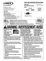
Illustration
P
T
23
22
7
21
5
3
6
4
2
1
18
17
11
19
8
16
10
14
15
13
12
9
25
28
24
24
36
37*
37*
36
34
35
33
32
30
29
31
27**
29
38
38
26
* Apply a thread sealant, such as
Loctite
®
242
®
Threadlocker, and
torque to 3.5 Nm (31 in-lb)
** Apply a thread sealant, such as
Loctite 242 Threadlocker

H4802, H4802-1, H4802-6, and 43227 Pole Tampers
Greenlee / A Textron Company 3 4455 Boeing Dr. • Rockford, IL 61109-2988 USA • 815-397-7070
Parts List
UPC No.
Key 78-3310- Part No. Description Qty
1 40293 111955 Body, tamper ................................................ 1
2 40180 104367K2 Ram .............................................................. 1
3 40377 114651 Gland, packing (includes items 4–7) ............. 1
4* 40367 114223K Seal, U-cup, .750 x 1.250 x .375 ................... 1
5* 41485 F015226K1 Seal, U-cup, .750 x 1.000 x .250 ................... 1
6* 41399 F012879 O-ring, 1.475 x 1.711 x .118–90 ................... 1
7* 41480 F014954 Wiper, rod, .750 x 1.125 x .281 .................... 1
8 40295 111957K1 Shaft ............................................................. 1
9 40297 111960 Spool ............................................................ 1
10 40296 111958 Body, valve.................................................... 1
11 42072 F023649 Plug, 7/8–14 UNF SAE O-ring boss,
socket head, steel ......................................... 1
12 40298 111961 Stop, spool.................................................... 1
13 40299 111962 Spring, compression, .330 x .500 x 1.250 .... 1
14 40300 111963K Plug, 7/8–14 UNF SAE O-ring boss,
hex head ....................................................... 1
15* 41398 F012815 O-ring, .755 x .949 x .097–90 ....................... 1
16* 41372 F011796 O-ring, .750 x .937 x .094–70 ....................... 3
17* 41331 F010777 O-ring, .375 x .500 x .062–70 ....................... 1
18 41691 F018347 Screw, cap, 5/16–18 x 1.000 socket head..... 4
21 40301 111964K Foot, tamper.................................................. 1
22 41257 F001362 Washer, flat, .375 x .875 x .075 .................... 1
23 41320 F010276 Screw, cap, 5/16–24 x 1.250 hex head ......... 1
24 41341 F010994 Adapter, 1/4 M NPT x 9/16–18 M JIC
(H4802, H4802-1, and H4802-6) .................. 2
25 49536 504 9536.4 Tube, handle (H4802 and H4802-6).............. 1
40358 113696 Tube, handle (H4802-1 and 43227) .............. 1
26 48303 48303 Adapter ......................................................... 1
27 41632 F017341 Screw, machine, 1/4–20 x .50 oval head
(H4802 serial codes FZP and FKA03499
and below, H4802-1 serial codes FZR and
FKM00019 and below, H4802-6 serial
codes FZT and FKF01499 and below,
and 43227) ................................................... 4
43095 F015251 Screw, cap, 1/4–20 x .75 flat head
(H4802 serial code FKA03500 and above,
H4802-1 serial code FKM00020 and
above, and H4802-6 serial code
FKF01500 and above) ................................... 4
UPC No.
Key 78-3310- Part No. Description Qty
28 41691 F018347 Screw, cap, 5/16–18 x 1.000 socket head..... 4
29 48369 48369 Hose, 3/8 x 56 with 9/16–18 JIC
swivel at both ends ....................................... 2
30 41413 F013326 Adapter, pipe, 9/16–18 UNF SAE O-ring
boss x 9/16–18 M JIC
(H4802 and H4802-1 ) .................................. 5
41413 F013326 Adapter, pipe, 9/16–18 UNF SAE O-ring
boss x 9/16–18 M JIC
(H4802-6 and 43227) ................................... 4
31 41422 F013518 Adapter, pipe, 9/16–18 M JIC x 3/4–16
UNF SAE O-ring boss
(H4802 and H4802-1) ................................... 1
32 40291 111953K Valve body, remote ON/OFF
(H4802 and H4802-1) ................................... 1
33 41888 F021673 Plug, pipe, 1/16 M NPT
(H4802 and H4802-1) ................................... 2
34 40340 113418 Spool (H4802 and H4802-1) ......................... 1
35* 41489 F015257 O-ring, .437 x .562 x .062–68
(H4802 and H4802-1) ................................... 2
36 40228 106576 Button, spool end (H4802 and H4802-1) ...... 2
37 41715 F018627 Screw, cap, #10–24 x .500 flat head
(H4802 and H4802-1) ................................... 2
38 41587 F016578 Ty, plastic (H4802, H4802-1
and H4802-6) ................................................ 4
41587 F016578 Ty, plastic (43227) ........................................ 4
39 40400 117961 Hose, 5/16 x 38.75 with 9/16–18 UNF
JIC swivel at both ends
(H4802 and H4802-6) ................................... 2
48368 504 8368.4 Hose, 5/16 x 68.75 with 9/16–18 UNF
JIC swivel at both ends
(H4802-1 and 43227) ................................... 2
Repair Kits
40290 111952 Control valve assembly (H4802 and
H4802-1 only; includes items 32–37)
40317 112875 Packing kit (includes items marked with
an asterisk)

H4802, H4802-1, H4802-6, and 43227 Pole Tampers
Greenlee / A Textron Company 4 4455 Boeing Dr. • Rockford, IL 61109-2988 USA • 815-397-7070
KEEP THIS MANUAL
Purpose of this Manual
This manual is intended to familiarize all personnel with the specifications
and parts for the following Fairmont tools:
H4802/42198 Serial Code FKA and FZP
H4802-1/42199 Serial Code FKM and FZR
H4802-6/42202 Serial Code FKF and FZT
43227 Serial Code FZV
Keep this manual available to all personnel.
Replacement manuals are available upon request at no charge.
Loctite and 242 are registered trademarks of Loctite Corporation.
Other Publications
Tool Owners/Users
Operation Manual: Publication 999 3019.6
SAE Standard J1273 (Hose and Hose Assemblies): Publication 999 3032.3
Authorized Fairmont Service Centers
Service Manual: Publication 999 1042.0
Specifications
Pole Tampers
Type of Hydraulic System ......................................Open-center or closed-center
Pressure Port .......................................................... 9/16–18 female SAE O-ring
Return Port ................................................................ 3/4–16 female SAE O-ring
Blows per Minute
@ 15 l/min (4 gpm).................................................................................. 980
@ 19 l/min (5 gpm)................................................................................ 1160
@ 23 l/min (6 gpm)................................................................................ 1300
Length
H4802 ..................................................................................... 1524 mm (60")
H4802-1 .................................................................................. 2134 mm (84")
H4802-6 .................................................................................. 1524 mm (60")
43227...................................................................................... 2134 mm (84")
Width ............................................................................................... 102 mm (4")
Mass/Weight
H4802 ..................................................................................... 10.4 kg (23 lb)
H4802-1 .................................................................................. 12.7 kg (28 lb)
H4802-6 .................................................................................. 10.4 kg (23 lb)
43227...................................................................................... 12.7 kg (28 lb)
Tamper Foot (kidney-shaped)................................. 64 mm x 203 mm (2.5" x 8")
All specifications are nominal and may change as design improvements occur.
Greenlee Textron Inc. shall not be liable for damages resulting from misapplica-
tion or misuse of its products.

H4802, H4802-1, H4802-6, and 43227 Pole Tampers
Greenlee / A Textron Company 5 4455 Boeing Dr. • Rockford, IL 61109-2988 USA • 815-397-7070
Specifications (cont’d)
Hydraulic Power Source
Do not exceed the following hydraulic power source maximums:
• Hydraulic flow: 23 l/min (6 gpm)
• Pressure relief: 138 bar (2000 psi)
• Back pressure: 13.8 bar (200 psi)
Failure to observe this warning could result in severe injury or death.
Type of Hydraulic System ......................................Open-center or closed-center
Flow
Minimum ............................................................................. 15 l/min (4 gpm)
Recommended ..................................................................... 19 l/min (5 gpm)
Maximum ............................................................................. 23 l/min (6 gpm)
Filtration ............................................................................. 10 micron (nominal)
Pressure Relief Setting .......................................................... 138 bar (2000 psi)
Back Pressure (maximum)* ................................................... 13.8 bar (200 psi)
* 13.8 bar (200 psi) is the maximum agreed standard back pressure for the
HTMA (Hydraulic Tool Manufacturers Association). Fairmont tools will
operate satisfactorily at this standard.
1. Maximum hydraulic fluid temperature must not exceed 60 °C (140 °F).
A sufficient oil cooling capacity is needed to limit the hydraulic fluid
temperature.
2. Hydraulic flow must not exceed 23 l/min (6 gpm). Install a flow meter in
the return line to measure the rate of hydraulic flow before using the tool.
3. Pressure relief valve setting must not exceed 138 bar (2000 psi) at the
tool’s maximum flow. Locate the pressure relief valve in the supply circuit
to limit excessive hydraulic pressure to the tool.
Recommended Hydraulic Fluids
Use any non-detergent, petroleum-based hydraulic fluid which meets the
following specifications or HTMA specifications.
S.U.S. @
38 °C (100 °F) ............................................................................... 140 to 225
99 °C (210 °F) ............................................................................ 40 minimum
Flash Point.................................................................. 170 °C (340 °F) minimum
Pour Point .................................................................. –34 °C (–30 °F) minimum
FILTER
(10 micron)
COOLER
RELIEF
VALVE
138 bar
(2000 psi)
CONTROL
VALVE
FLOW METER
T
P
TOOL
RESERVOIR
PUMP
POWER SOURCE
Hydraulic Schematic

USA 800-435-0786 Fax: 800-451-2632
815-397-7070 Fax: 815-397-1865
Canada 800-435-0786 Fax: 800-524-2853
International +1-815-397-7070 Fax: +1-815-397-9247
4455 Boeing Drive • Rockford, IL 61109-2988 • USA • 815-397-7070
An ISO 9001 Company
•
Greenlee Textron Inc. is a subsidiary of Textron Inc.
www.greenlee.com
Printed in USA
/