Honeywell RTH8580WF User manual

Category
Thermostats
Type
User manual
User Guide
Wi-Fi Touchscreen
Programmable Thermostat
Model RTH8580WF
69-2715ES—01
69-2715ES—01 ii
In the box you will find
• Thermostat
• Wallplate (attached to thermostat)
• Screws and anchors
• Coin cell battery (inside the back of the thermostat)
• Quick Start Guide
• Thermostat ID Card
• Wire labels
• User Guide
Welcome
Congratulations on your purchase of a Honeywell Wi-Fi
touchscreen programmable thermostat. When registered
to Honeywell’s Total Connect Comfort Solutions, you
can remotely monitor and control the heating and
cooling system in your home or business— you can stay
connected to your comfort system wherever you go.
Honeywell’s Total Connect Comfort is the perfect
solution if you travel frequently, own a vacation home,
a business or manage an Investment property or if you
are simply looking for peace of mind.
69-2715ES—01 2
This thermostat works on 24 volt systems. It will NOT work on 120/240 volt systems.
This thermostat contains a Lithium battery which may contain Perchlorate material.
Perchlorate Material—special handling may apply.
See www.dtsc.ca.gov/hazardouswaste/perchlorate
MERCURY NOTICE: Do not place your old thermostat in the trash if it contains
mercury in a sealed tube. Contact the Thermostat Recycling Corporation at www.
thermostat-recycle.org or 1-800-238-8192 for information on how and where to
properly and safely dispose of your old thermostat.
NOTICE: To avoid possible compressor damage, do not run air conditioner if the
outside temperature drops below 50°F (10°C).
Need help?
Visit wifithermostat.com or call 1-855-733-5465 for assistance before returning the
thermostat to the store.
69-2715ES—01 3
About your new thermostat
Home screen quick reference ..................... 5
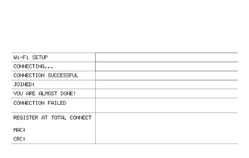
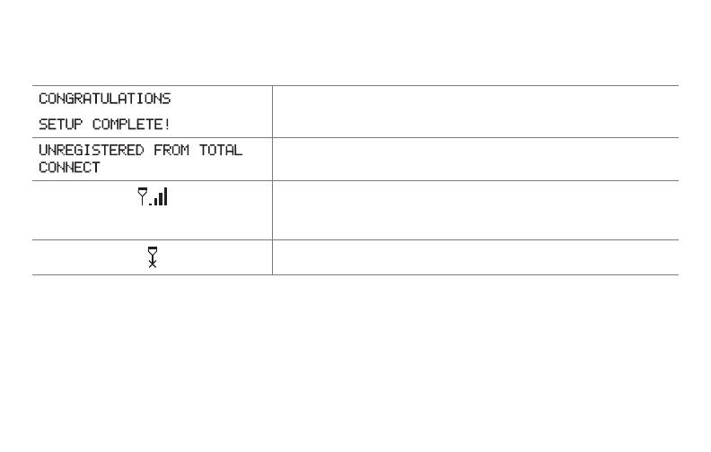
Message center messages ......................... 6
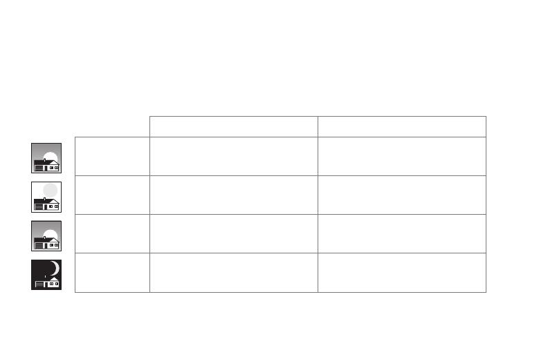
Preset energy-saving schedules ................. 8
Installation
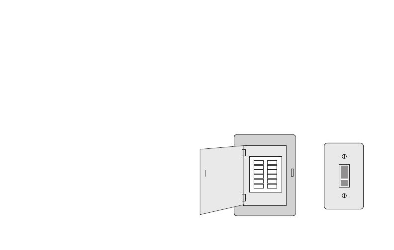
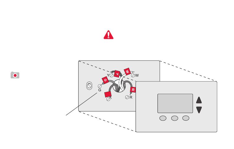
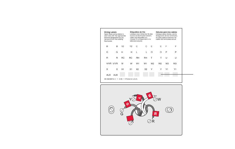
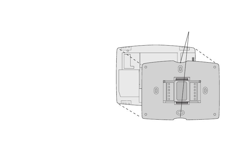
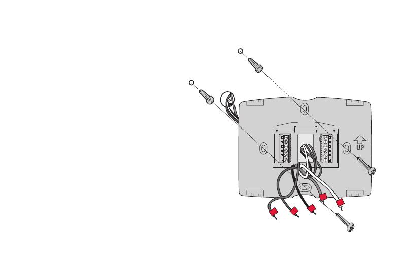
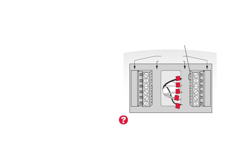
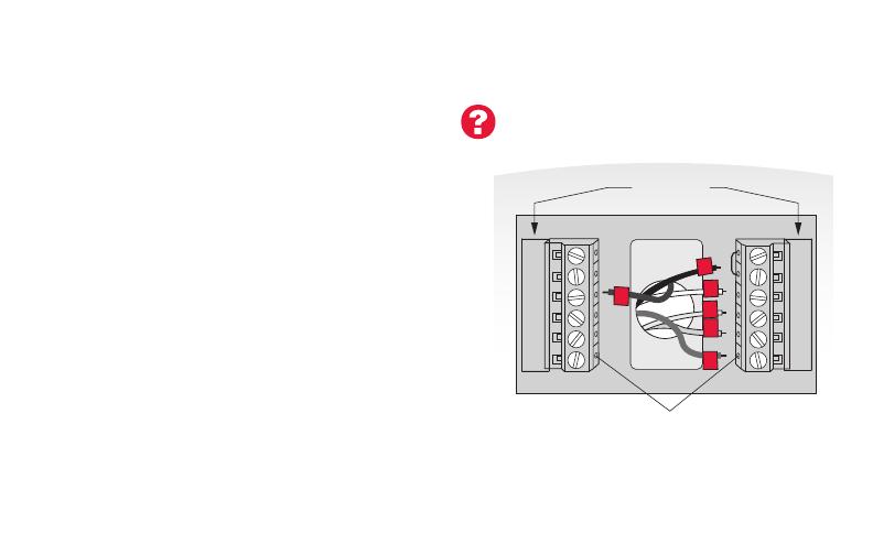
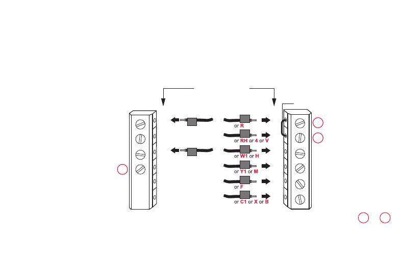
Installing your thermostat .......................... 10
Connecting to your Wi-Fi network ............. 27
Registering your thermostat online ........... 32
Operation
Setting the clock ........................................37
Setting the fan ........................................... 38
Selecting system mode ............................. 39
Adjusting program schedules ....................40
Overriding schedules temporarily .............41
Overriding schedules permanently ........... 42
Setting vacation hold .................................43
Setting filter reminder intervals ................. 44
Cleaning the screen .................................. 45
Unregistering thermostat...........................46
Disconnecting Wi-Fi .................................. 47
Special features ........................................48
Setting functions and options .................... 51
Appendices
Frequently asked questions ...................... 59
Troubleshooting ......................................... 62
Limited warranty ........................................68
Table of contents
69-2715ES—01 4
Features of your Wi-Fi thermostat
With your new thermostat, you can:
• Connect to the Internet to monitor and control your heating/cooling system
• View and change your heating/cooling system settings
• View and set temperature and schedules
• Receive alerts via email and get automatic upgrades
Your new thermostat provides:
• Smart Response Technology
• Compressor protection
• Heat/cool auto changeover
5 69-2715ES—01
Home screen quick reference
Once your Wi-Fi thermostat is installed, it will display the home screen. Portions of this
display will change depending on how you are viewing it. To change settings, simply press
the appropriate area lightly with your finger.
Unless you change the lighting function, the screen is always lit at low intensity. When you
touch the screen, the screen brightens.
Set clock
Message center
Select fan mode
Select system mode
Program schedules
Override schedule
Wi-Fi status
Schedule is on (does not
display when off)
Additional settings
Lock screen for cleaning
MXXX24
MORE
Inside
69-2715ES—01 6
Message center messages
The Message Center at the top of the screen communicates Wi-Fi connection and
registration status. It also displays the MAC ID and MAC CRC for registering the
thermostat at mytotalconnectcomfort.com
Displayed before you begin Wi-Fi setup.
Displayed while connecting to the Wi-Fi network.
Displayed after connecting to the Wi-Fi network.
[Wi-Fi network name]
Displayed when connected to the Wi-Fi network.
Displayed when Wi-Fi connection is complete.
Displayed when the thermostat fails to establish a connection
to the Wi-Fi network.
Displayed when the thermostat is connected to the Wi-Fi
network but not registered at mytotalconnectcomfort.com.
Displays the thermostat’s MAC ID and MAC CRC for
registering at mytotalconnectcomfort.com.
[Found on your ID card]
[Found on your ID card]
7 69-2715ES—01
Message center messages
Displayed when the thermostat is registered at
mytotalconnectcomfort.com.
Displayed when the thermostat is removed from your Total
Connect Comfort account.
Wi-Fi signal strength. Displayed when the thermostat
is connected to the Wi-Fi network and registered at
mytotalconnectcomfort.com
Displayed if there is no Wi-Fi signal.
69-2715ES—01 8
Preset energy-saving schedules
This thermostat is pre-set with energy-saving program settings for four time periods.
Using the default settings can reduce your heating/cooling expenses by as much as 33%
if used as directed. Savings may vary depending on geographic region and usage.
Default Heat Settings Default Cool Settings
WAKE
6:00 am
70
°
78
°
LEAVE
8:00 am
62
°
85
°
RETURN
6:00 pm
70
°
78
°
SLEEP
10:00 pm
62
°
82
°
To change the settings, see pages 40–43.
9 69-2715ES—01
Setting up your thermostat
Setting up your Wi-Fi programmable touchscreen thermostat is easy. It is preprogrammed
and ready to go as soon as it is installed and registered.
Install your thermostat.
Connect it to your home wireless network.
Register online for remote access.
Before you begin, you may want to watch a brief installation video. Use the QR Code
®
at
the front of this guide, or go to wifithermostat.com.
2
3
1
69-2715ES—01 10
Installing your thermostat
You might need the following tools to install this thermostat:
• No. 2 Phillips screwdriver
• Small pocket screwdriver
• Pencil
• Level (optional)
• Drill and bits (3/16” for drywall,
7/32” for plaster) (optional)
• Hammer (optional)
• Electrical tape (optional)
1 Switch OFF power.
To protect your equipment, switch
OFF the power to your heating/cooling
system at the breaker box or the
system switch.
or
M31535
11 69-2715ES—01
C
C
MCR33823
If you have an older thermostat with a
sealed mercury tube, turn to page 2
for proper disposal instructions.
Terminal
designation
Installing your thermostat
2 Remove old thermostat.
Remove the old
thermostat while leaving
the wallplate and wiring
in place.
Take a picture of the
wires on your old
thermostat for later
reference.
69-2715ES—01 12
Installing your thermostat
3 Label wires.
Use the supplied sticky tags
to label each wire as you
disconnect it. Label wires
according to the old thermostat
terminal designations, not by
wire color.
Note: If no tag matches a
wire terminal label, write the
terminal label on a blank tag.
Blank tags
C
C
MCR31537
13 69-2715ES—01
M31538
Installing your thermostat
4 Remove wallplate.
Remove the old wallplate from the wall
after all wires have been labeled and
disconnected.
5 Separate Wi-Fi thermostat and its
wallplate.
On your new thermostat, grasp the
finger holds on the top and bottom of
the wallplate with one hand and the
thermostat (front) with the other hand.
Pull pieces apart.
Thermostat
Wallplate (back view)
Finger holds
69-2715ES—01 14
Installing your thermostat
6 Mount wallplate for Wi-Fi thermostat.
Mount your new wallplate using
screws and anchors included with the
thermostat.
If necessary:
Drill 3/16-in holes for drywall.
Drill 7/32-in holes for plaster.
M31543
Y2
W2
K
RC
R
W
Y
G
C
RC
R
O/B
Y
G
C
HEAT PUMP
CONVENTIONAL
L
E/AUX
K
R
Y
C
W
G
MCR31539
Wallplate
15 69-2715ES—01
Note: The Wi-Fi thermostat requires a C wire to operate. The C, or common,
wire brings 24 VAC power to the thermostat. Many older mechanical or battery
operated thermostats do not require a C wire. If you don’t have a C wire, try:
• Looking for an unused wire that is pushed into the wall. Connect that wire
to C and check that it is connected to the 24 VAC common at your heating/
cooling system. Check the video section at wifithermostat.com.
• Installing a new wire. If required, contact a contractor to install a new wire
(go to wifithermostat.com to locate a contractor in your area).
Wiring
For conventional heating/cooling systems (natural gas, oil or electric furnace, air
conditioner), see page 16. See “Glossary” on page 65 for further definition.
For a heat pump system, see page 17. See “Glossary” on page 65 for
further definition.
Installing your thermostat
69-2715ES—01 16
Y2
W2
K
RC
R
W
Y
G
C
RC
R
O/B
Y
G
C
R
W
G
C
Y
HEAT PUMP
CONVENTIONAL
L
E/AUX
K
MCR31541
Installing your thermostat
Wiring (conventional system)
7A Connect wires.
Wire the Wi-Fi thermostat to your conventional
system.
a Match the labels on the wires to the
terminal labels. You must have a C wire.
See page 15.
b Loosen screws, insert wires into holes
on inside edge of terminals, then tighten
screws.
c Push any excess wire back into the wall
opening.
d Continue to page 22.
Remove metal jumper
if you have both
R and RC wires
Labels don’t match? See alternate
wiring key on pages 18–19.
17 69-2715ES—01
Installing your thermostat
Wiring (heat pump system only)
7B Connect wires.
Wire Wi-Fi thermostat to your heat pump.
a Match the labels on the wires to the
terminal labels on the new thermostat.
You must have a C wire. See page 15.
b Loosen screws, insert wires into holes
on inside edge of terminals, then tighten
screws.
c If old thermostat has separate wires on
AUX and E, place both wires into the
E/AUX terminal. If old thermostat has wire
on AUX with a jumper to E, place wire on
E/AUX terminal. No jumper is required.
d Push any excess wire back into the wall
opening.
e
Continue to page 22.
Labels don’t match? See alternate
wiring key on pages 20–21.
MCR33529
RC
R
O/B
Y
G
C
HEAT PUMP
L
E/AUX
K
R
O
G
Y
C
AUX
Insert wire here
69-2715ES—01 18
Installing your thermostat
Y2
W2
K
Y2
W2
RC
R
W
Y
G
C
RC
R
W
Y
G
C
1
2
3
CONVENTIONAL
Metal Jumper
Alternate wiring (conventional system)
Use this if your wire labels don’t match the terminal labels.
Note: You must have
a C wire or equivalent.
See page 15.
See key to
1
3
on page 19.
  • Page 1 1
  • Page 2 2
  • Page 3 3
  • Page 4 4
  • Page 5 5
  • Page 6 6
  • Page 7 7
  • Page 8 8
  • Page 9 9
  • Page 10 10
  • Page 11 11
  • Page 12 12
  • Page 13 13
  • Page 14 14
  • Page 15 15
  • Page 16 16
  • Page 17 17
  • Page 18 18
  • Page 19 19
  • Page 20 20
  • Page 21 21
  • Page 22 22
  • Page 23 23
  • Page 24 24
  • Page 25 25
  • Page 26 26
  • Page 27 27
  • Page 28 28
  • Page 29 29
  • Page 30 30
  • Page 31 31
  • Page 32 32
  • Page 33 33
  • Page 34 34
  • Page 35 35
  • Page 36 36
  • Page 37 37
  • Page 38 38
  • Page 39 39
  • Page 40 40
  • Page 41 41
  • Page 42 42
  • Page 43 43
  • Page 44 44
  • Page 45 45
  • Page 46 46
  • Page 47 47
  • Page 48 48
  • Page 49 49
  • Page 50 50
  • Page 51 51
  • Page 52 52
  • Page 53 53
  • Page 54 54
  • Page 55 55
  • Page 56 56
  • Page 57 57
  • Page 58 58
  • Page 59 59
  • Page 60 60
  • Page 61 61
  • Page 62 62
  • Page 63 63
  • Page 64 64
  • Page 65 65
  • Page 66 66
  • Page 67 67
  • Page 68 68
  • Page 69 69
  • Page 70 70
  • Page 71 71
  • Page 72 72

Honeywell RTH8580WF User manual

Category
Thermostats
Type
User manual

Ask a question and I''ll find the answer in the document

Finding information in a document is now easier with AI