
Installation of the RDR (Radio Data Receiver) low-voltage unit will enable you to remotely operate your existing
Vari-Time 4000 satellite controller using a hand-held DTMF radio and/or OSMAC base station. This document covers the
recommended installation procedures and operation of the completed RDR system.
CAUTION: Unless there is a separate agreement between Toro and the original end-user purchaser, Toro
does not warrant the installation, maintenance or service of the system in which the RDR unit is utilized. Toro
assumes no obligation for system design, installation and maintenance. Consult a licensed electrician for
installation and design.
End-user purchaser is responsible for obtaining a radio license for the operation of this equipment.
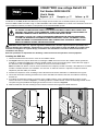
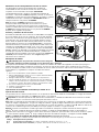
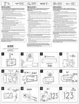
Installing the RDR Unit
1. Unlock and remove the front access cover of the satellite cabinet.
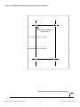
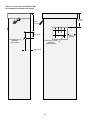
2. See Figure 13 for the proper dimensions if installing the RDR unit on the back of the satellite cabinet (preferred
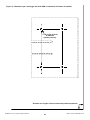
method). If installing the RDR unit inside the satellite cabinet on the rear mounting plate, remove the back page of
this document and use
Figure 14 as a template for the four screw hole locations.
Note: The RDR unit utilizes a built-in antenna located on the frequency module assembly. If the RDR unit is installed
inside the satellite cabinet or site conditions are such that an alternate antenna is required, an optional antenna
adapter kit (P/N 102-1204) is available.
3. Position the template or mark according to the indicated measurements. Drill holes as indicated on the figures.
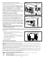
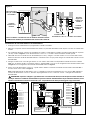
4. Locate the removable mounting bracket on the back of the RDR unit. Release the latch and slide the mounting
bracket out.
5. If installing the mounting bracket on the back of the satellite cabinet, use the provided #10-32 machine screws,
washers and nuts as shown in
Figure 1. If installing inside the satellite cabinet, secure the mounting bracket on the
rear plate using the provided self-tapping sheet metal screws as shown in
Figure 2.
6. Slide the RDR unit onto the mounting bracket until the bracket latch engages the RDR enclosure.
Figure 1 Figure 2
WARNING
ALL WIRING TO THE EXISTING SATELLITE CONTROLLER MUST COMPLY WITH LOCAL AND
NATIONAL ELECTRICAL CODE STANDARDS. TORO IS NOT RESPONSIBLE FOR INJURIES OR
EQUIPMENT DAMAGE DUE TO IMPROPER CONTROLLER INSTALLATION.
DISCONNECT 120/240 V A.C. INPUT POWER WHEN SERVICING THE EXISTING IRRIGATION
SYSTEM. THE IRRIGATION SYSTEM INCLUDES SPRINKLERS, VALVES, SOLENOIDS, PIPING,
WIRING BETWEEN SYSTEM COMPONENTS AND CONTROLLER. FAILURE TO COMPLY CAN
RESULT IN SERIOUS INJURY OR ELECTROCUTION.
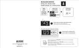
OSMAC
®
RDR Low-voltage Retrofit Kit
Part Number RDR0160LVCE
User’s Guide
Español - p. 9 Français - p. 17 Italiano - p. 25

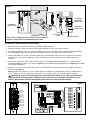
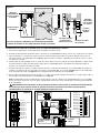
Installing the Station Wires and Power Wires
1. Disconnect the primary power source to the existing satellite controller.
2. Unlock the satellite cabinet front cover and the RDR unit door to access the station terminals.
3 For exterior installation, install 1/2" (13mm) flexible water-proof conduit between the satellite cabinet and the RDR
unit. See
Figure 3. Separate conduit must be installed for the 24 V a.c. power wire and station wires.
4. Using 14–16 AWG (2.5–1.5mm
2)
) stranded copper wire, route individual station and valve common wires from the
satellite terminal strip into the RDR unit. Label and identify each wire for connection to the RDR output board
terminals.
5. Secure each station wire and the valve common wire to its associated RDR station terminal; i.e., satellite station 1
connected to RDR unit station 1, etc. Refer to
Figure 4 for the satellite terminal configuration and Figure 5 for the RDR
unit terminal configuration.
6. Route 24 V a.c. power and common wires from the terminal block and secure both wires to the RDR transformer
terminals. See
Figure 5.
Note: The RDR unit requires a 24 V a.c. power supply. If installing on a controller other than the VT 4000, locate a
24 V a.c. power source from within the controller or from an outside source to connect the RDR transformer.
CAUTION: Up to three valve solenoids can be connected to each station, not to exceed 0.75A maximum
output per station. During operation, a maximum of five solenoids can be operated simultaneously, not to
exceed 1.25A maximum current draw. Exceeding these limits can cause equipment damage.
2
90˚ Liquid Tight
Non-Metallic
Conduit Fitting
Liquid Tight
Non-Metallic
Conduit Fitting
Non-Metallic
Flexible Conduit
Non-Metallic
Flexible Conduit
24 V a.c. Power Wire
Conduit
Station Wire Conduit
24 VAC
Common
Station 1
Station 2
Station 3
Station 4
Station 5
Station 6
Station 7
Station 8
Station 9
Station 10
Station 11
Figure 3
Figure 4
Figure 5
Note: Conduit and fittings are not provided but must be installed as
required to comply with Local and National Electrical Code.

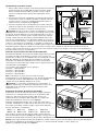
Installing the Earth Ground
1. Route the green ground wire from the RDR unit transformer
terminal block to the cabinet rear plate. Secure the ground wire
ring terminal to the rear plate using the provided self-tapping
sheet metal screw. See
Figure 6.
2. Remove the lock nut from the lower right corner of the rear
plate. Install the provided star washer, copper ground lug and
lock nut. Tighten securely. See
Figure 6.
3. Connect the copper ground lug to an earth grounding device
using 6 AWG (10mm
2
) bare copper wire. Avoid bends in the
ground wire of less than 8" (20cm) radius.
Important: Make sure the satellite is properly connected to an
earth ground device such as a 5/8" x 8' (16mm x 2.5m) copper clad
rod driven into the earth at a distance from the satellite from 8' to 12’
(2.5–3.7m). The top of the ground rod should be buried 12" (30.5cm)
below grade level. Using an earth ground resistance testing device, a
reading of 0 ohms is optimum, up to 10 ohms is good and 11–30
ohms is acceptable in most cases. If the resistance exceeds the
acceptable limit, an additional ground rod can be installed at a
distance equal twice the length of first rod; i.e., 16' (4.9m). Connect the ground rods using 6 AWG (10mm
2
) bare copper
wire and test again. If the ground resistance remains high, contact your local Toro distributor for further assistance and
recommendations.
Selecting the Decoder Radio Frequency
The narrow-band frequency decoder module stores four user-
selectable radio frequencies. The frequencies are programmed at
the factory or by the distributor prior to delivery of the RDR unit.
A set of jumper pins, located on the RDR frequency decoder module
enables the frequency to be selected by placing the jumper on the
appropriate channel pin set. See
Figure 7.
The pre-programmed frequencies are as follows:
Channel #1 = 462.2125 MHz
Channel #2 = 462.4375 MHz
Channel #3 = 467.2125 MHz
Channel #4 = 467.4375 MHz
Note: There will be cases where the four pre-programmed
frequencies are not suitable for use in the area. The frequency
programming kit (P/N 102-1208) can be used to program any
available user-defined frequency.
Important: The base station transmitter, hand-held radio and the
RDR frequency decoder module must be set to the same frequency
to enable communication.
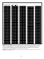
Assigning the Satellite Address Number
Each satellite requires a three-digit address number to enable
communication with the central controller and/or a hand-held radio.
The address numbers range from 1 (001) through 255 and is set by
the DIP switches located on the frequency decoder module
assembly. See
Figure 8.
In the down position, the switch is Off (open) and represents a value
of 0 (zero). In the On position, the closed and represents the
following address number:
Sw 1 = 1 Sw 2 = 2 Sw 3 = 4 Sw 4 = 8
Sw 5 = 16 Sw 6 = 32 Sw 7 = 64 Sw 8 = 128
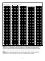
To set the satellite address number, first locate the desired satellite
address in
Table 1 on page 4. Next, position each switch On or Off
as indicated on the chart.
Example: To set satellite address number 50 (050), start with all eight DIP switches in the Off (open) position, then set
switch numbers 2, 5 and 6 to the On position (
2 [2] + 16 [5] + 32 [6] = 50. See Figure 8.
Figure 6
#1
#2
#3
#4
Figure 7
O
12345678
N
Figure 8
Ground Lug
Star Washer
RDR Ground
Connection
6 AWG (10mm
2
)
Wire From Earth
Ground Device
Lock Nut
Transformer
Ground Terminal
3

Electromagnetic Compatibility
Domestic: This equipment has been tested and found to comply with the limits for a FCC Class A digital device, pursuant to part 15 of the FCC
Rules. These limits are designed to provide reasonable protection against harmful interference when the equipment is operated in a commercial
environment. The equipment generates, uses, and can radiate radio frequency energy and, if not installed and used in accordance with the
instruction manual, may cause harmful interference to the radio communications. Operation in a residential area is likely to cause harmful
interference in which case the user will be required to correct the interference at his own expense.
International: This is a CISPR 22 Class A product. In a domestic environment, this product may cause radio interference, in which case the user
may be required to take adequate measures.
4
001
002
003
004
005
006
007
008
009
010
011
012
013
014
015
016
017
018
019
020
021
022
023
024
025
026
027
028
029
030
031
032
033
034
035
036
037
038
039
040
041
042
043
044
045
046
047
048
049
050
051
052
053
054
055
056
057
058
059
060
061
062
063
064
065
066
067
068
069
070
071
072
073
074
075
076
077
078
079
080
081
082
083
084
085
086
087
088
089
090
091
092
093
094
095
096
097
098
099
100
101
102
103
104
105
106
107
108
109
110
111
112
113
114
115
116
117
118
119
120
121
122
123
124
125
126
127
128
129
130
131
132
133
134
135
136
137
138
139
140
141
142
143
144
145
146
147
148
149
150
151
152
153
154
155
156
157
158
159
160
161
162
163
164
165
166
167
168
169
170
171
172
173
174
175
176
177
178
179
180
181
182
183
184
185
186
187
188
189
190
191
192
193
194
195
196
197
198
199
200
201
202
203
204
205
206
207
208
209
210
211
212
213
214
215
216
217
218
219
220
221
222
223
224
225
226
227
228
229
230
231
232
233
234
235
236
237
238
239
240
241
242
243
244
245
246
247
248
249
250
251
252
253
254
255
Table 1 - DIP Switch Address Configurations
= ON = OFF
DIP Switch Number
1 2 3 4 5 6 7 8

Performing a Control Circuit Self Test
A self-test feature is provided to check the functionality of various
key satellite control circuits.
The test is initiated by positioning the TEST/RESET switch, located
on the frequency decoder module, to the
TEST position as shown
in
Figure 9. Testing will begin immediately. The test will repeat
continuously until the
TEST/RESET switch is positioned to the
NORMAL position.
Note: The RESET position resets the frequency decoder
microprocessor to factory defaults. To take affect, the satellite must
be powered up with the switch in the
RESET position. The switch
should be placed in the
NORMAL position after 15 seconds of
operation.
Remote Relay Function and Connection
The RDR unit frequency decoder module is equipped with a single-
pole, double-throw 5.0 amp relay. The relay is intended for use in
irrigation installations which have two different irrigation systems.
Upon transmitted command from the base station or a hand-held
radio, the relay can be energized. This will stop all OSMAC RDR
functions and turn power on to the alternate irrigation system.
Another command can be sent to the RDR to turn off the relay, de-
energizing the alternate system and returning control to the
OSMAC RDR. Additionally, a command is provided to disable this
feature so it cannot be accidentally activated and a different
command to enable the feature. See the
Command Code list for
specifics. See
Figure 10 for the terminal locations.
Fuse Replacement
CAUTION: For continued protection against risk of fire,
replace the fuse with the same type and rating only.
The RDR unit transformer assembly and the terminal output boards are equipped with fuses to protect the unit from
damage due to power surges and excessive current draw from the station terminals. Before replacing the fuse, check for
the probable cause, such as a shorted or improperly connected station or common wire, then replace the fuse as follows:
1. Disconnect the primary power source to the satellite.
2. Unlock the RDR unit to access the transformer assembly
and/or terminal output boards.
3. Carefully remove the blown fuse from its retaining clip.
4. Install a replacement fuse to the retaining clip. Use a 2 amp
slow-blow fuse for the transformer assembly and a 4 amp
slow-blow fuse for the terminal output boards.
5. Reconnect power to the RDR unit.
6. Test for proper operation
7. Lock the RDR unit.
Satellite Operations Using a Hand-Held Radio
Satellite operations can be initiated using a hand-held radio with DTMF keypad. The operation command codes are listed
in
Table 2 below and page 6.
Important: The base station transmitter/hand-held radio and the RDR frequency decoder module must be set to the
same frequency to enable communication.
Note: All operation commands must begin with the following keypad sequence:
*
9 followed by the three-digit satellite
address number. The command code is then entered, followed by additional digits which represent selected stations
and/or run time values. The
# key is pressed at the end of the command sequence. All station numbers from 1–9 must be
entered with a preceding
0; i.e., station 1 is entered as 01.
Example: Confirm communication to the satellite by issuing a manual station start command as follows: Press
*
9,
the three-digit satellite address code, command code
7521 01 (station 1) and #. Check for sprinkler operation. To step
forward through the stations, press
*
1; to step back through the stations, press
*
2. To terminate the test, press
*
9, the
three-digit satellite address code and command code
7520 #.
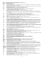
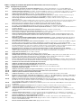
Table 2 - Hand-Held Radio Command Codes (continued on p.6)
Note: When issuing commands from the base station keypad, use the dash (–) key in lieu of the star (
✱
) key.
Code Operation Description
7510 Turns off individual stations; e.g., 7510 01 02 11 turns off stations 1, 2 and 11.
7511 Turns on individual stations; e.g., 7511 01 02 11 turns on stations 1, 2 and 11.
Figure 9
COM
12 345
24 V a.c.
4A Slow-Blow Fuse
Figure 11
Figure 10
5
Reset
Test
Normal

Table 2 - Hand-Held Radio Command Codes (continued from p. 5)
Code Operation Description
7512 Syringes individual stations for a predetermined time. Use command 8006 01 to set the syringe time; e.g. 7512 01 02
turns on stations 1 and 2 for the specified time.
7513 Disables individual stations; e.g., 7513 01 03 disables stations 1 and 3. After this command, on and off commands will
be ignored for stations 1 and 3 until the stations are re-enabled. (See 7514.)
7514 Enables individual stations; e.g., 7514 01 03 enable stations 1 and 3.
7515 Sequentially syringes a specified station number range; e.g., 7515 05 11 will syringe stations
5 through 11 sequentially. Command 8006 01 sets the syringe time.
7516 Sequentially syringes individual stations; e.g., 7516 10 11 will syringe stations 10 and 11.
Note: Multiple syringe groups can also be run. Enter two stars between stations to designate separate syringe groups;
e.g., 7516 10 11
**
22 24 26 28 will run two syringes at the same time. First on stations 10 and 11, followed by stations
22, 24, 26 and 28.
7517 Turns on individuals stations for a specified number of hours, minutes and seconds;
e.g., 7517 01 30 00 05 06 09 turns stations 5, 6 and 9 on for 1 hour, 30 minutes and no seconds.
7518 Turns on individual stations for a specified number of minutes; e.g., 7518 10 05 06 turns on stations 5 and 6 for 10
minutes.
7520 Turns off a sequential station run operation (initiated by command code 7521).
7521 Turns on a sequential station run operation; e.g., 7521 01 turns on station 1. To step forward through the stations,
press
*
1; to step back through the stations, press
*
2.
7522
Increment to the next predetermined station in a sequential run; e.g., 7522 02 will add 02 to the station number of the
currently running station and energize the new station number. The sequential run will stop when the new number exceeds 64.
7523
Decrement to the previous predetermined station in a sequential run; e.g., 7523 03 will run the station that is 3 stations
before the one currently running. The sequential run will stop when station number reaches the new station number minus 1.
7524 Turns on individual stations as switches; i.e., does not simultaneously energize the pump. Note: Will not turn off the
pump if already running. E.g., 7524 01 03 11 turns on stations 1, 3 and 11 without energizing the pump.
7525 Turns on individual stations as switches for a time given in minutes; i.e., does not simultaneously energize the pump
in this command string, the run time is entered first, followed by the station numbers; e.g., 7525 25 05 11 turns on stations
5 and 11 for 25 minutes without energizing the pump.
7526 Turns on individual stations as switches for the time given in hours, minutes and seconds.
In this command string, the run time is entered first, followed by the station numbers; e.g., 7526 02 30 45 05 06 07 turns
on stations 5, 6 and 7 for 2 hours, 30 minutes and 45 seconds.
7540 Turns off all stations (this satellite only).
7542 Turns off all stations using the sequential shut down feature.
7543 Disables all stations in all satellites (rain shutdown). Note: Satellite address code 256 is used with 7543 or 7544
command codes. The stations will not respond to any further commands until enabled.
7544 Enables operation of all stations in all satellites. See Note above.
7546 Sequentially syringes all stations for a set length of time; e.g., 7546 turns on all stations for the predetermined number
of 30 second intervals as defined in the syringe time.
7800 Disable the remote relay on the frequency decoder module.
7801 Enable the remote relay on the frequency decoder module.
7810 Turns off the remote relay on the decoder module.
Resumes function to the satellite unit.
7811 Turns on the remote relay on the decoder module. Disables function to the satellite unit.
8000 Disables pump start.
8001 Enables pump start to be assigned to a station
; e.g., 8001 10 assigns pump start to station 10.
8003 00 Disables operation and turns off all stations in the satellite with sequential shutdown.
8003 01 Enables operation of all stations in the satellite.
8004 Changes the password
; e.g., 8004 7531 6108 will change the factory default password (7531) to 6108.
8006 01 Sets the syringe time in 30-second intervals; e.g., 8006 01 0100 (without a password) or 8006 pppp 01 0100.(with a
password) sets the syringe time to 100 intervals (50 minutes). The number of intervals must be given as four digits with
leading zeros but can be no greater than 0255.
8006 02 Sets the time-out limit in 30-minute intervals. Must be specified using four digits with leading zeros and no greater value
than 0255; e.g., 8006 02 0060 (without password) or 8006 pppp 02 0060 (with password) sets the time-out limit to 30 hours.
8006 03 Enables/disables the password. Use 8007 03 01 to enable password protection or 8007 03 00 to cancel password protection.
8007 03 00 Password disable command. Cancel the requirement of entering the password for every entered command.
8007 03 01 Password enable command. After activation, all commands will require the password to be entered.
8008 Configures stations as switches. Stations can be specified individually and in combination with a range of stations;
by using the star key; e.g., 8008 01 03 08
*
11 configures stations 1, 3 and 8 through 11 as switches.
8009 Configures stations for irrigation. Stations can be specified individually and in combination with a range of stations;
by using the star key; e.g., 8008 01 03 08
*
11 configures stations 1, 3 and 8 through 11 for irrigation.
8011 Resets EPROM to factory defaults.
*
1 Sends command 752201 to the last satellite addressed. Increments station number in test mode by one.
*
2 Sends command 752301 to the last satellite addressed. Turns off current station be tested and decrements station
number in test mode by one.
*
4 Sends command 7540 to the last satellite addressed. Turns off all stations
6

7
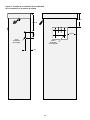
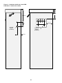
Figure 13 - RDR Installation Detail
For Satellite Exterior Installation
2" (5.0 cm)
2" (5.0 cm)
6" (15.24 cm)
7/8" (22 mm)
Diameter
(Two Places)
7/32" (5.5 mm)
Diameter
(Four Places)
3 1/2"
(8.89 cm)
5" (12.7 cm)

© 2003 The Toro Company, Irrigation Division Form Number 373-0261 Rev. A
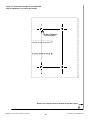
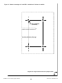
Align with the lower right corner of the rear plate.
1/8" (3.2mm) Diameter
(Four Places)
Figure 14 - RDR Mounting Template For Satellite Interior Installation
8
Page is loading ...
Page is loading ...
Page is loading ...
Page is loading ...
Page is loading ...
Page is loading ...
Page is loading ...
Page is loading ...
Page is loading ...
Page is loading ...
Page is loading ...
Page is loading ...
Page is loading ...
Page is loading ...
Page is loading ...
Page is loading ...
Page is loading ...
Page is loading ...
Page is loading ...
Page is loading ...
Page is loading ...
Page is loading ...
Page is loading ...
Page is loading ...
-
 1
1
-
 2
2
-
 3
3
-
 4
4
-
 5
5
-
 6
6
-
 7
7
-
 8
8
-
 9
9
-
 10
10
-
 11
11
-
 12
12
-
 13
13
-
 14
14
-
 15
15
-
 16
16
-
 17
17
-
 18
18
-
 19
19
-
 20
20
-
 21
21
-
 22
22
-
 23
23
-
 24
24
-
 25
25
-
 26
26
-
 27
27
-
 28
28
-
 29
29
-
 30
30
-
 31
31
-
 32
32


Toro RDR0160LVCE User manual
- Type
- User manual
- This manual is also suitable for
Ask a question and I''ll find the answer in the document
Finding information in a document is now easier with AI
in other languages
- italiano: Toro RDR0160LVCE Manuale utente
- français: Toro RDR0160LVCE Manuel utilisateur
- español: Toro RDR0160LVCE Manual de usuario
Related papers
-
Toro OSMAC RDR Satellite Series Product Literature
-
-
-
-
Toro 4500-D User manual
-
-
Toro 100 User manual
-
-
-
Other documents
-
Optimus MP-A1 User manual
-
CAME 818XA-0051 Installation guide
-
Rain Bird ESP-Modular Owner's manual
-
 PRO-DF AL69001 User manual
-
ICP DAS USA I-7531 User manual
-
Sony RDR-HX910 Operating instructions
-
-
Sony GX-700 User manual
-
-
 PRO-DF AL66005 Installation guide

