Page is loading ...

22
Index: page
1 Warnings 3
2 Product description and applications 4
2.1 Operating limits 5
2.2 Typical system 5
2.3 List of cables 5
3 Installation 6
3.1 Preliminary checks 6
3.2 Diagram of the connections: 6
3.3 Description of the connections: 7
4 Adjustments: 8
4.1 Functioning modes: 8
5 Programming: 8
5.1 Programmable functions: 9
5.2 Description of the functions: 9
6 Testing 10
6.1 Commissioning 12
7 Maintenance and Disposal 12
7.1 Maintenance 12
7.2 Disposal 12
8 Accessories 12
9 Technical characteristics 13
EN

33
This manual contains important information regarding safety. Before
starting installation of the components, it is important that you read
all the information contained herein. Store this manual safely for
future use.
Due to the dangers which may arise during both the installation and
use, installation must be carried out in full observance of the laws,
provisions and rules currently in force to ensure maximum safety.
This chapter provides details of general warnings. Other more spe-
cicwarningsaredetailedinChapters“3.2PreliminaryChecks”and
“6TestingandCommissioning”.
!
According to the most recent European legislation, the
automation of doors or gates is governed by the provisions
listed in Directive 98/37/CE (Machine Directive) and, more
specically the standards: EN 13241-1 (harmonised stand-
ard); EN 12445; EN 12453 and EN 12635, which enables the
declaration of machine conformity to the machine directive.
Visit“www.niceforyou.com”forfurtherinformationandguidelinesfor
risk analysis and how to draw up the Technical Documentation. This
manualhasbeenespeciallywrittenforusebyqualiedtters.Except
fortheenclosedspecication“InstructionsandWarningsforUsers”
to be removed by the installer, none of the information provided in
this manual can be considered as being of interest to the end users!
• Any use or operation not explicitly provided for in these instructions
is not permitted. Improper use may cause damage and personal
injury.
• A risk analysis must be carried out before starting installation,
including a the list of essential safety requisites provided for in
EnclosureIofthe MachineDirective,indicatingtherelativesolu-
tions employed. N.B. Risk analysis is one of the documents
includedinthe“TechnicalDocumentation”forthisautomation.
• Check whether additional devices are needed to complete the
automation based on the specic application requirements and
dangers present. The following risks must be considered: impact,
crushing, shearing, dragging, etc. as well as other general dan-
gers.
•Donotmodifyanycomponentsunlesssuchactionisspeciedin
this manual. Operations of this type are likely to lead to malfunc-
tions.NICEdisclaimsanyliabilityfordamageresultingfrommodi-
edproducts.
• During installation and use, ensure that solid objects or liquids do
not penetrate the control unit or other open devices. If necessary,
contacttheNICEcustomerservicedepartment;useinthesecon-
ditions can be dangerous.
• The automation system must not be used until it has been com-
missionedasdescribedinchapter6“Testingandcommissioning”.
• The packaging materials must be disposed of in compliance with
local regulations.
• If a fault occurs that cannot be solved using the information pro-
videdinthismanual,contacttheNICEcustomerservicedepart-
ment.
• In the event that any automatic switches are tripped or fuses
blown, attempt to identify and eliminate the relative fault.
• Disconnect all the power supply circuits before accessing the ter-
minalsinsidethecover.Ifthedisconnectiondeviceisnotidenti-
able,afxthefollowingsign:“WARNING:MAINTENANCEWORK
INPROGRESS”.
Special warnings concerning the suitable use of this product in rela-
tiontothe98/37CE“MachineDirective”(ex89/392/CEE):
•Thisproductisissuedonthemarketasa“machinecomponent”
and is therefore manufactured to be integrated in a machine or
assembledwithothermachinesinordertocreate“amachine”,in
accordancewiththedirective98/37/EC,exclusively incombina-
tion with other components and in the manner described in the
presentinstructionsmanual.Asspeciedinthedirective98/37CE
the use of this product is not admitted until the manufacturer of
themachineonwhichthisproductismountedhasidentiedand
declareditasconformingtothedirective98/37/CE.
Special warnings concerning suitable use of this product in relation
tothe73/23/EEC“LowVoltage”Directiveandsubsequentamend-
ments93/68/CEE:
•Thisproductcomplieswiththeprovisionsenvisagedbythe“Low
Voltage” Directive if used in the congurations foreseen in this
instruction manual and in combination with the articles present in
the Nice S.p.a. product catalogue. If the product is not used in the
speciedcongurationsorisusedwithotherproductsthathave
notbeenforeseen,therequirementsmaynotbeguaranteed;use
of the product is prohibited in these conditions until compliance
withtherequirementsforeseenbythedirectivehasbeenveried
by installers.
Special warnings concerning suitable use of this product in relation
to the 89/336/EEC “Electromagnetic Compatibility” Directive and
subsequentamendments92/31/EECand93/68/EEC:
• This product has undergone tests regarding electromagnetic com-
patibilityinthemostcriticalofuseconditions,inthecongurations
foreseen in this instruction manual and in combination with articles
present in the Nice S.p.A. product catalogue. Electromagnetic
compatibilitymaynot beguaranteedifused in congurationsor
with other products that have not been foreseen; use of the
product is prohibited in these conditions until compliance with the
requirementsforeseenbythedirectivehasbeenveriedbyinstall-
ers.
1) Warnings
EN

4
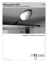
Theelectroniccardissuitableforcontrollingroadboomgatesmodels“WIL 4”and“WIL 6”with24Vd.c.motors.
The actuator has a limit switch with a speed control system that makes it possible to reach the travel limits by means of a slowing down
phase. In addition, the effort the motor is subject to during movement is promptly detected as well as any obstacles that may be in the path
and in such an even direction is reversed.
Itcanbecontrolled“manually”,“semiautomatically”or“automatically”.Therearealsocertainfunctionslike“RecloseimmediatelyafterPho-
tocell”or“Reclosealways”,“Flashingalsoinpause”aswellasotheroperatingfunctionssuchas“GradualStart-up”and“Slowingdown”(a
standardfeature)plusasensitive“Brake”thatonlycomesintoplayifmovementhastobestoppedhastily.
ThetaskoftheOKLED(7)istosignalthecorrectfunctioningoftheinternallogic;itmustashat1secondintervalsandindicatesthatthe
internal microprocessor is working and waiting for commands. Whenever there is a variation in the state of the inputs or of the function dip-
switches(1),adouble,quickashingisgeneratedeveniftheeffectsofthevariationarenotimmediate.
Whentheunitispowered,theluminousindicators(16)ontheinputsturnonifthatparticularinputisactiveandifthereisacontrolvoltageof
24Vcc.Asarule,theLEDsonthesafetydeviceinputsSTOP,PHOTOCELLandPHOTOCELL2andthoseonthelimitswitchesarealways
onwhilethoseontheSTEP-BY-STEP,OPENandCLOSEarenormallyoff.
Duringmovement,thecurrentabsorbedbythemotorismeasured;whenitexceedsacertainlimit(adjustablewiththetrimmer)thesafety
systemisactivatedwhichcausesmovementtostopwiththeaidofthebrake(removingtheresidualpartofaccumulatedkineticenergy);then,
if one of the automatic functioning modes is active, a movement in the opposite direction starts. To increase the level of safety still further, if
theSTOP_AMPEREsystemcomesintoplaythreeconsecutivetimeswithouteverreachinganyofthenaturalendsofthemovement,anal
STOP is carried out.
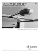
1 Function selection dip-switch
2 OKled
3 “I”TrimmerSTOP_AMPERE
4 “TP”TrimmerPAUSETIME
5 “FL”TrimmerWORKFORCE
6 “FR”TrimmerDECELERATIONFORCE
7 Microprocessor
8 CHARGEboardconnector
9 Limit switch connector
10 RADIO connector
11 Radio input connector
12 Input/output terminal board
13 Flashing light output terminal board
14 Motor output connector
15 Power supply terminal board
16 Input status indicator led
17 Fuse(3.15Aif230Vac)or(5Aif120Vac)
18 Fuse 8 A
19 Fuse 1 A
2) Product description and applications
1
EN

5
2.1) Operating limits
Chapter9“TechnicalCharacteristics”providestheonlydataneededtodeterminewhethertheproductsaresuitablefortheintendedappli-
cation.
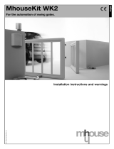
2.2) Typical system
NOTE: This diagram only shows a possible application of the unit and should be considered merely as an example. Only an in-depth analysis
oftherisksofthe“Machine”gateandaproperevaluationoftheenduserrequirementswillbeabletoestablishhowmanyandwhichele-
ments must be installed.
1. WIL Barrier
2. Selector post
3. Key-operatedselectorswitch
4. Radio keypad
5. Photocell post
6. pair of PHOTO photocells
7. Luminous indicator
8. Luminous indicator
9. Closing rod
10. Sensitive edge on PHOTO 1
11. Adhesive warning strip
12. ashinglight
13. RADIO aerial
14. Radio transmitter
2
2.3) List of cables
Thetypicalsystemshowningure2alsostatesthecablesrequiredforconnectionofthevariousdevices,thespecicationsofwhichare
provided in table 1.
!
The cables used must be suitable for the type of installation; for example, an H03VV-F type cable is recommended for indo-
or applications, while H07RN-F is suitable for outdoor applications.
Note 1: power supply cable longer than 30 m may be used provided it has a larger gauge, e.g. 3x2,5mm
2
, and that a safety earthing system
is provided near the automation unit.
Connection Cable type Maximum admissible length
A:Electricalpowerline N°1cable3x1,5mm
2
30m(note1)
B:Flashinglight N°1cavo2x0,5mm
2
20m
C: Aerial N°1shieldedcabletypeRG58 20m(lessthan5mrecommended)
D:Photocells N°1cable2x0,25mm
2
(Tx) 30m
N°1cable4x0,25mm
2
(Rx) 30m
E: Key-operatedselectorswitch N°1cable4x0,25mm
2
30m
F:Sensitiveedge N°1cable2x0,25mm
2
30m
G:Photocells N°1cable2x0,25mm
2
30m
N°1cable4x0,25mm
2
30m
Table 1: List of cables
EN

6
!
The installation must be carried out by qualied personnel in compliance with current legislation, standards and regulations,
and the directions provided in this manual.
3) Installation
3.1) Preliminary checks
Before proceeding with the installation:
• Check that all the materials are in excellent condition, suitable for
use and compliant with current standards.
• Ensure that the mounting positions of the various devices are
protected from impact and that the mounting surfaces are suf-
cientlysturdy.
•Installcableorpipeleadsonlyatthe bottom of the unit; for no
reason whatsoever must the side and top walls be perforated. The
cables must only enter the unit from the bottom!
• Components must never be immersed in water or other liquids.
•Keepawayfromheatsourcesandopenames;inacid,salineor
potentially explosive atmosphere; this could damage and cause
malfunctions or hazardous situations.
• Only connect the control unit to a power supply line equipped with
a safety grounding system.
• The power supply line must be protected by suitable magnetother-
mal and differential switches.
• A disconnection device must be inserted in the power supply
linefromtheelectricalmains(thedistancebetweenthecontacts
must be at least 3.5 mm with an overvoltage category of III) or
equivalent system, for example an outlet and relative plug. If the
disconnection device for the power supply is not mounted near the
automation, it must have a locking system to prevent unintentional,
unauthorised connection.
3.2) Diagram of the connections
Installationofthebarrierandrelativecontrolelements(keyselectororpushbuttonpanel)andsafety(emergencystop,photoelectriccells,
sensitiveedgesandashinglight)elementshavebeeninstalled,youcannowdothewiring,followingtheinstructionsgivenbelow.
!
Tosafeguardtheoperatorandavoiddamagingthecomponentswhileyouarewiring,whetheritislowvoltage(230-120Vac)orextralow
voltage(24V)orifyouareplugginginthevariouscards:
The unit must, under no circumstances, be electrically powered.
WealsowishtoremindyouthatiftheinputsoftheNC(NormallyClosed)contactsarenotusedtheyshouldbejumpered;ifthereismore
thanonethentheyshouldbeplacedinSERIESwithoneanother;iftheinputsoftheNO(NormallyOpen)contactsarenotusedtheyshould
beleftfreeandifthereismorethanonethentheyshouldbeplacedinPARALLELwithoneanother.Thecontactsmustbeofthemechanical
typeandfreefromanypotential;noconnectionsareallowedlikethosedenedas“PNP”,“NPN”,“OpenCollector”etc.,etc.
Carry out the necessary connections, following the diagram in Fig. 4 and the following description of the connections.
!
Rememberthat therearespecicstandardsthatmustbecompliedwith bothasregardsthesafetyof theelectricalsystems andas
regards automatic gates.
EN

7
3.3) Description of the connections
Here is a brief description of the possible connections of the unit to the outside:
1-2 : 230 V a.c. = 230 V a.c. 50/60 Hz
3-4 :Flashinglight =Outputforconnectiontothe24Vd.c.ashinglight,maximumlamppower:25W
5-6 :24Vd.c. =24Vd.c.outputforsupplyingaccessories(Photocell,Radio,etc.)maximum200mA
7 :Common =Commonforallinputs(terminal6canalsobeusedastheCommon)
8 : Courtesy Light = 24 V d.c. output for the courtesy light, maximum output power 10 W
9 :C.A.Indicator =InputwithSTOPfunction(Emergency,shutdownorextremesafety)
10 :Stop =Inputforsafetydevices(Photocells,pneumaticedges)
11 :Photocell =Inputforsafetydeviceswithtriggeringintheopeningphase(Photocells,pneumaticedges)
12 : Photocell2 = Input for safety devices with triggering
13 :Step-by-Step =Inputforcyclicfunctioning(OPENSTOPCLOSESTOP)
14 :Open-Timer =Inputforopening(whichcanbetimercontrolled)
15 : Close = Input for closing
: Aerial = Input for the radio receiver aerial
The remaining connections are done in the factory but for the sake of completeness here is the list:
TRANS.PRIM. = Primary of the power transformer
TRANS.SECOND. = Secondary of the power transformer
MOTOR = Output for 24 V d.c. motor connection
There are an additional two slots for optional cards:
RADIO = Slot for Nice radio receivers
CHARGE = Slot for battery charge card
Aerial
OK
FCA
FCC
CHARGE
RADIO
Close
Open-Timer
Step-by-Step
Photocell2
Photocell
Stop
C.A. Indicator
Courtesy Light
Common
24 Vdc
max 200 mA
Flashing light 24 Vdc
max 25 W
230 Vac
50-60 Hz
Primary of the power transformerSecondary of the power transformer
3
EN

8
NOTE:Adjustmentofthe(FL)and(FR)trimmersaltersthespeedofthebarrierasthisisconnectedwithFORCE.
AdecreaseinFORCEcausesadecreaseinspeed.
I LastlyadjustthetrimmerSTOP_AMPEREsotheobstacledetectingsystem,basedonanammetricfrictionsystem,isactivatedassoon
as an appropriate opposite action is applied to the bar. The ammetric friction system comes into play in both directions.
TPIfyouhavechosentheautomaticfunctioningmode(dip-switchNo.2ON),theendoftheopeningmanoeuvreisfollowedbya“pause”
timeattheendofwhichaclosingmanoeuvrefollowsautomatically.ThetimestaysopencanbeadjustedwiththePAUSETIMEtrimmer
for the length of time you want, without any limits. An automatic closing manoeuvre and the relative pause time are activated also in the
semiautomatic functioning mode when, in closing, the triggering of a safety device will cause the gate to reverse direction
4) Adjustments
FL Adjustment of the WORK FORCE trimmer enables
control of the barrier speed
FRAdjustment of the DECELERATION FORCE trimmer
enables setting of the required thrust to ensure cor-
rect operation in the deceleration phase so that the
rodreachesthestoppointsas“smoothly”aspossible
without jolting; the perfect setting of the balancing
spring is fundamental of course.
4.1) Functioning modes
InthemanualfunctioningmodetheOPENinputallowsmovement
uptotheopeningpoint;theCLOSEinputallowsmovementupto
the closing point; STEP-BY-STEP allows alternative opening and
closing manoeuvres; as soon as the command in input stops,
movement stops. In the opening phase movement stops when the
maximum opening point is reached or if there is no consent from
PHOTOCELL2;tothecontrary,intheclosingphasemovementwill
stop at the maximum closed point or if there is no consent from the
PHOTOCELL.If STOPistriggereditwillcausemovementtostop
immediately both in the opening and closing manoeuvres. Once
movement has stopped the command in input has to be stopped
beforeanynewmovementscanberective).
Ineither oftheautomaticfunctioning modes(semiautomatic-auto-
maticandclosesalways)acommandontheOPENinputwillcause
anopeningmanoeuvre;ifthecommandremains(TIMER)oncethe
barisopen,thebarremains“frozen”inaninnitepause;onlywhen
the command stops will the bar be able to close. Command pulses
ontheCLOSEinputwillcauseaclosingmanoeuvre;ifthecommand
remains the bar will stay locked in the closed position until the com-
mandceasesandonlythencanitbereopened.ApulseonSTEP-
BY-STEPcausesalternativeopeningandclosing.
Asecondpulseon the STEP-BY-STEPoronthesameinputthat
started the movement, will cause a Stop.
Whether in the opening or closing phase, if STOP triggers it will
cause movement to stop immediately.
In an opening manoeuvre, triggering of the PHOTOCELL has no
effectwhilePHOTOCELL2willcausereversalofmovement;inaclo-
singmanoeuvre,triggeringofthePHOTOCELLcausesmovementto
reverse followed by a new pause and lastly reclosing.
Ifatthebeginningofanopeningmovement,thePHOTOCELLinput
does not give consent, the request to open is cancelled.
If the automatic functioning mode is being used, there will be a
pause time subsequent to an opening manoeuvre and followed by
aclosingmanoeuvre.If,duringthepausethePHOTOCELLtriggers,
thetimerwillberesetwithanewtime;if,ontheotherhand,aSTOP
comes into play during the pause, the reclosing function will be can-
celled and there will be a STOP condition.
The unit comprises a set of microswitches used to operate various
functions so as to render the system more suitable to user needs
and safer in the different ways of usage. All functions are activated
by placing the dip-switch in the “ON” position while they will not
be activated if the corresponding dip-switches are “OFF”; some
functions do not have an immediate effect and only have sense in
certain conditions like.
!
ATTENTION:someoftheprogrammablefunctionsarelinkedto
safety aspects, very carefully evaluate the effects of a function and
see which function gives the greatest possible level of safety.
When servicing a system, before you modify a programmable fun-
ction, ascertain the reason why, during installation, certain choices
were made and then verify if, with the new programming, safety will
be impaired.
5) Programming
EN

9
5.1) Programmable functions
Switches1-2: OffOff =“Manual”movement(ManPresent)
OnOff =“Semiautomatic”movement
OffOn =“Automatic”movement(AutomaticClosing)
OnOn =“Automatic+AlwaysCloses”movement
Switch 3: On = Condominium functioning mode
Switch 4: On = Cancels STOP in the Step-by-Step cycle
Switch5: On =Preashing
Switch 6: On = Flashing also in Pause
Switch7: On =ReclosesstraightafterPhotocell(onlyifonAutomatic)
Switch8: On =Safety(Photocell)alsoinopening
Switch9: On =Baropenindicatorbecomestrafclightinthe“one-way”mode
Switch10: On =Functioninginthe“Trafclightinbothdirections”mode
5.2) Description of the functions
Switches 1-2: OffOff =“Manual”movement(ManPresent)
OnOff =“Semiautomatic”movement
OffOn =“Automatic”movement
(AutomaticClosing)
OnOn =“Automatic+AlwaysCloses”movement”
Wheninthe“Manual”functioningmode,movementwillonlybecar-
riedoutwhilethecommandisbeinggiven(buttonpressed).
Inthe “Semiautomatic” mode just one command pulse is needed
and the complete manoeuvre will be carried out until it is either
fullyopenorfullyclosed.Inthe“Automatic”functioningmodeone
command pulse will cause an opening manoeuvre to be carried out
followed by a pause and then a closing manoeuvre.
The“AlwaysCloses”functionworksif,subsequenttoatemporary
powercut,thebarisstillopen;inthiscase,aclosingmanoeuvreis
startedautomaticallyprecededby5secondsofpreashing.
Switch 3: On = Condominium function
In the Condominium functioning mode, once an opening manoeuvre
has started, for instance with a Step-by-Step pulse, it cannot be
interruptedbyanyothercommandpulsesuntilithasnished.
During a closing manoeuvre, a new command pulse will stop the bar
and immediately reverse the direction, opening the bar.
Switch 4: Cancels STOP in the Step-by-Step cycle
TheStep-by-Stepcycleisnormally:OPEN-STOP-CLOSE-STOP;in
this functioning mode the Step-by-Step cycle becomes:
OPEN-CLOSE-OPENsothe bar canneverstopmidway,butonly
when completely open or completely closed.
Switch 5:On=Preashing
Theashinglightstartspriortoeachmovement;after5seconds(2
secondsifonmanual)movementstarts.
Switch 6: On = Flashing also in Pause
Theashinglightisnormallyactivatedonlyduringtheopeningand
closing manoeuvres; with this function the ashing light remains
activealsoduringthePauseTimetosignalthe“closingsoon”con-
dition.
Switch 7:On=Recloses straightafterPhotocell(onlyifonAuto-
matic:Sw2=ON)
With this function the bar can be kept open only for the length of
timeneeded fortransit;infact,itwillclose automaticallyalways5
seconds after the last object has passed by the “Photocell”, irre-
spective of the programmed Pause Time.
Switch 8:On=Safety(Photocell)alsoinopening
As a rule the safety “Photocell” only works in the closing cycle; if
switch8is“ON” the triggering of the safety device will causethe
bartostopevenintheopeningphase;ifonSemiautomaticorAuto-
matic, movement will start again, in opening, immediately after the
last object has passed by the Photocell.
Switch 9:Baropenindicatorbecomestrafclightinthe“one-way”
mode
As an alternative to the Gate Open indicator, the output can be
reprogrammedsothatitperformsthefunctionofa“one-way”trafc
light;thismeanstheoutputisoffwhenthebarisclosedorclosing,
and on when the bar is opening or is opened. In this way, an indica-
tioncanbexedtotheexitlike:Green=Transitfree.
Switch 10:Functioninginthe“Trafclightinbothdirections”mode
Several changes occur in the control unit when the “Trafc light in
bothdirections”functionisactivatedwhenSwitch10isON:
OPENbecomesSTEP-BY-STEP2,whilethetwooutputs,Courtesy
Light and Bar Open Indicator become a Green Light in both direc-
tions. Due to the specic nature of this function we are giving a
separate description.
EN

10
Trafc light in both directions:
Thefunctionofthetrafclightinbothdirectionsismainlytocontroltheowoftrafcinbothdirectionsastheygoacrossthecontrolled
roadbarrier.Adifferentcommandisplacedforopeninginbothdirections:P.P.forenteringandP.P.2(Open)forleaving;twotrafclightsare
installed with the indications Red and Green, connected to the Bar Open Indicator and Courtesy Light outputs.
Thetwooutputsareusuallyoffandsoarethetwotrafclights;whenacommandisgivenwithP.P.toenter,movementisstartedandthe
Bar Open Indicator output is activated: this means there will be a green light to enter and a red light to leave.
But should the command be given with the P.P.2, the Courtesy Light output will be activated and there will be a green light to leave and a red
lighttoenter.Thelightwillstayonfortheentireopeningmanoeuvreandforthesubsequentpausetime;duringtheclosingmanoeuvreboth
thegreenandredlightswillbeactivated(theresultbeingyellow)toindicatethereisnolongeranytransitpriority(seetable).
The two Bar Open Indicator and Courtesy Light outputs can directly control small 24 V d.c. lamps for a total of 10 W. If stronger lamps have
tobeused,usetherelayspilotedbytheunitoutputsthatcontrol,inturn,thetrafclights.
Red Green Meaning:
OFF OFF Bar closed, no passage in either direction
OFF ON Bar open, free transit
ON OFF Bar open, transit occupied
ON ON Bar closing and transit not controlled
TRAFFIC LIGHT
Lamp max 5W
COMMAND
CON : P. P.
COMMAND
CON : P. P. 2
ENTER
WIL
C.A. Indicator (9)
Cortesy light (8)
EXIT
!
This is the most important stage in the automation system instal-
lation procedure in order to ensure maximum safety levels. Testing
can also be adopted as a method of periodically checking that all the
various devices in the system are functioning correctly.
Testing of the entire system must be performed by qualied and
experienced personnel who must establish which tests to conduct
on the basis of the risks involved, and verify the compliance of the
system with applicable regulations, legislation and standards, in
particularwithalltheprovisionsofENstandard12445whichestab-
lishes the test methods for automation systems for gates.
We recommend working in the manual mode with all the functions
deactivated(dip-switchesOFF);inallcases,whenyouareworking
in the manual mode and you release the control key the motor will
stop immediately.
Each component of the system, e.g. safety edges, photocells,
emergencystop,etc.requiresaspecictestingphase,wetherefore
recommend observing the procedures shown in the relative instruc-
tion manuals.
Ensurethattheinstructionsoutlinedinthismanualandinparticular
inchapter1“WARNINGS”havebeenobservedinfull.
A)Check that the bar is well balanced, adjusting the balancing
spring if necessary.
Release the boom gate using the special spanner and check that
the bar can move without any effort for the whole length of travel.
B)Powertheunitandcheckthatvoltagebetweenterminals1-2and
1-3 is 230 / 120 Vac and 24 V a.c. between terminals 21-22.
Assoonastheunitispoweredtheindicatorlights(LEDs)ontheactive
inputsshouldlightup;inaddition,the“OK”LEDshouldstartashing
almost immediately afterwards at regular intervals. If none of this hap-
pens, switch power off and check connections more carefully.
• Thetaskofthe“OK”LED,inthecentreofthecard,istosignalthe
stateoftheinternallogic:regularashingat1secondintervals
means the internal microprocessor is working and waiting for
commands. On the other hand, when the same microprocessor
recognisesavariationinthestateofaninput(beitacommand
inputorfunctiondip-switch),adouble,quickashingisgenerat-
edeveniftheeffectsofthevariationarenotimmediate.Extrafast
ashingfor3secondsmeansthattheunithasjustbeenpowered
6) Testing
EN

11
andiscarryingoutatestoftheinternalparts;lastlyanirregular,
nonconstantashingmeansthatthetestwasunsuccessfuland,
consequently, there is a failure.
C)NowcheckthattheLEDsofinputswithNCtypecontactsareon
(allthesafetydevicesactive)andthattheLEDsofinputswithNO
typecontactsareoff(nocommandpresent);ifthisdoesnothap-
pen check connections and effectiveness of the various devices.
D)Checkthatallthesafetydevicesontheplantareworkingproperly
(emergency stop, photoelectric cells, pneumatic edges, etc.);
eachtimetheytriggerthecorrespondingSTOP,PHOTOCELLor
PHOTOCELL1shouldturnoff.
• This is one of the most important checks and must be done with
greatcare,inactualfactthe“active”safetyofthegatemachine
depends on the correct functioning of the safety devices. If the
ashinglightisanexcellentinstrumentforsignallingthestateof
danger and the torque limiting devices are an excellent means
to minimise damages, only a correct installation of the safety
devices will make it possible to block the automatism before it
can cause any damage.
E) Nowisthetimetocheckwhethermovementoccursintheright
direction, that is, to see whether movement set on the unit cor-
responds to that of the gates.
This check is of paramount importance, if the direction is wrong in
somecases(inthesemiautomaticfunctioningmodeforinstance),
thegatemightappeartobeworkingproperly;infact,theOPEN
cycleissimilartotheCLOSEcyclebutwithonebasicdifference,
the safety devices are ignored in the closing manoeuvre which is
normally the most dangerous, and they will trigger in the opening
manoeuvre causing the gate to reclose up against the obstacle
with disastrous results!
Locktheboomgatewiththebarata45°anglesoitcanmovefreely
inbothdirections.NowgiveabriefcommandpulseontheOPEN
input and if the bar does not move in the opening direction proceed
as follows:
1) Turntheelectricityofftotheboomgate
2) Unplugthe“MOTOR”connectorandreplugitafterithasbeen
turned180°
3) Unplugthe“LIMITSWITCH”connectorandreplugitafterithas
beenturned180°
RepeattheproceduredescribedaboveinpointEtoseeifrotation
direction is right.
Note:
when direction is reversed then all the three procedures described
above have to be carried out. In particular, if, for example, you turn
the“MOTOR”connectorbutnotthe“LIMITSWITCH”connectorit
will cause an error in the slowing down system. In such a case, the
motor is controlled, for instance, in the opening phase but the FCA
limit switch is never reached and consequently the bar reaches the
openingpointwithmaximumforce;theammetricdetectingsystem
then comes into play reversing direction in a new manoeuvre which
is also wrong.
F) Havingcheckedallconnectionsandmotorrotationdirection,itis
possible to try a complete movement, we recommend that you
always work in the manual mode with all functions deactivated. If
youusetheStep-by-Stepasthecommandinput,therstmove-
ment(afterturningon)shouldbeanopeningone.
By means of the command inputs, move the bar up to the opening
point;about20°fromthestoppingpointtheFCAlimitswitchshould
trigger,activatingthe“slowingdown”phasewhichmakesthebar
reach the set point at a slower speed. Now carry out a closing
phaseuntiltheclosingpointisreached;inthiscasetoo,theFCC
limitswitchshould trigger, activating theslowing down phase 20°
before movement stops. Now test triggering of the safety devices:
PHOTOCELLinopeninghasnoeffectwhileintheclosingphaseit
causesthebartostop;PHOTOCELL2hasnoeffectintheclosing
phase while in the opening phase it causes the bar to stop. The
devices connected to the STOP input act both in the opening and in
the closing phases, causing the bar to stop.
G) Thehazardoussituationscausedbythemovementhavebeen
safeguarded by limiting the force of impact, the impact force
must be measured according to EN Standard 12445. If the
controlofthe“motorforce”isusedtoassistthesystemforthe
reductionoftheimpactforce,trytondtheadjustmenttoobtain
optimal results.
There is a trimmer on the card to establish the triggering threshold of
thisthefriction;ishastobeadjustedsothatitcomesintoactionas
soon as a light pressure is applied to the bar in the direction opposite
to the way it is moving.
To overcome the initial movement phase that always needs greater
motorpower,theSTOP_AMPEREfrictionsystemisexcludedfrom
themotorstartupphase;toevaluatetheeffectoftheadjustmenton
the trimmer, you ought to wait until the movement has started and
the bar has reached standard speed.
Keep in mind that, always for a question of safety, if the friction
comes into play three consecutive times, movement is stopped with-
out any reversal. If the automatic functioning mode is selected at the
endoftheopeningmanoeuvre,thereisa“pausetime”afterwhicha
closing manoeuvre is automatically launched. Pause time is adjusted
withthetrimmerPAUSETIME.Pausetimeis alsoactivatedinthe
semiautomatic functioning mode when, in the closing phase, the
triggeringofasafetydeviceortheSTOP_AMPEREfriction,causes
a reversal in the opening manoeuvre.
EN

12
6.1) Commissioning
Commissioning can take place only after all the testing phases of
the control unit and the other devices have been completed suc-
cessfully. It is not permissible to execute partial commissioning or to
enable use of the system in makeshift conditions.
1. Prepare and store for at least 10 years the technical documenta-
tion for the automation, which must include at least the following:
assembly drawing of the automation, wiring diagram, analysis
of hazards and solutions adopted, manufacturer’s declaration of
conformityofallthedevicesinstalled(forWILusetheannexedCE
declarationofconformity);copyoftheinstructionmanualandmain-
tenance schedule of the automation.
2.Afxadataplateonthegateprovidingatleastthefollowingdata:
type of automation, name and address of manufacturer (person
responsibleforthe“commissioning”),serialnumber,yearofmanu-
factureand“CE”marking.
3.Permanentlyxalabelorplateinthevicinityoftheautomation,
stating the procedures for release and manual manoeuvres.
4. Prepare the declaration of conformity of the automation system
and deliver it to the owner.
5.Preparethe“Instructionsandwarningsfortheuseoftheautoma-
tionsystem”anddeliverittotheowner.
6. Prepare the maintenance schedule of the automation system and
deliverittotheowner(thismustprovidealldirectionsregarding
themaintenanceofthesingleautomationdevices).
7. Before commissioning the automation system inform the owner in
writingregardingresidualrisksandhazards(e.g.inthe“Instructions
andwarningsfortheuseoftheautomationsystem”).
7.1) Maintenance
The automation must undergo maintenance work on a regular basis,
in order to guarantee prolonged lifetime.
The maintenance operations must be performed in strict
compliance with the safety directions provided in this manual
and according to the applicable legislation and standards.
If other devices are present, follow the directions provided in the cor-
responding maintenance schedule differents from WIL.
1. Is requires scheduled maintenance work every 6 months or
10,000manoeuvres(max.)afterpreviousmaintenance.
2. Disconnect all power supplies.
3. Check for any deterioration of the components which form the
automation, paying particular attention to erosion or oxidation of
the structural parts. Replace any parts which are below the required
standard.
4. Connect the electric power sources up again, and carry out the
testingandchecksstatedinParagraph“6Testing”.
!
This charter provides information about how to draw up a maintenance schedule, and the disposal.
7) Maintenance and Disposal
7.2) Disposal
As in the case of installation, at the end of the product lifetime, dis-
posalproceduresmustbecarriedoutbyqualiedpersonnel.
This product comprises various types of materials, some of which
can be recycled while others must be disposed of. Check informa-
tion on the recycling and disposal procedures according to local
legislation for this product category.
!
Some parts of the product may contain pollutant or haz-
ardous substances; if disposed of into the environment these
may constitute a serious risk of damage to the environment
and public health.
As indicated by the symbol in gure
never dispose of this product in domestic
waste. Apply “classied waste collec-
tion”proceduresfordisposalinaccord-
ance with local regulations or return the
product to the retailer when purchasing
a new model.
Localregulationsmayenvisageserious nesintheevent ofillegal
disposal of this product.
“RADIO” CARD:
The control unit features a connector for plugging in an SM radio
card , which activates the inputs and allows the control unit to be
remote-controlled through a transmitter.
output 1 STEP-BY-STEP
output 2 Stop
output 3 Open
output 4 Close
“CHARGE” CARD also battery powered:
Theroadboomgate“Wil”isequippedwithapowertransformerthat
can withstand the energy required by both the motor and electronic
card so it can all be powered directly by the mains.
If you want the system to work even when there is a power cut then
you have to add a suitable battery and relative battery charger card.
The battery must be installed in its own compartment outside the
plastic box that protects the gearmotor card and connected to two
terminalsonthebatterychargercard;thelattermustbeconnected
to the connector on the unit.
Consult the Nice S.p.a. product catalogue for the complete and
updated list of accessories.
8) Accessories
EN

13
With the aim of improving products, Nice S.p.a reserves the right to modify technical characteristics at any time without notice, while main-
taining the same functionalities and intended use.
Alltechnicalcharacteristicsstatedrefertoanambienttemperatureof20°C(±5°C).
9) Technical characteristics
PowerWIL4–WIL6 230Vac±10%,50-60Hz
PowerWIL4/V1–WIL6/V1 120Vac±10%,50-60Hz
Batterypower 21-28Vd.c.(>6Ahcapacity)
Max. current accessories, 24 V d.c. 200 mA
Max.powerashinglight 25W(24Vd.c.)
Max.powerCourtesyLight 10W(24Vd.c.)
Max. power Open Bar indicator 10 W [24 V d.c.]
Maximum frequency of operating cycles unlimited
Maximum time of continuous operation unlimited
Pause time from 3 to 120 seconds
Courtesy light time 60 seconds
Operatingtemperature -20to70°C
Size 280 x 220 x 110 mm
Weight 3,7 kg
Protectionlevel IP55(containerundamaged)
EN
/