Page is loading ...

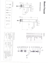
SPREAD LAVATORY
FAUCETS
Installation
Instructions
Thank you for selecting American-Standard...
the benchmark of fine quality for over 100 years.
To ensure that your installation proceeds smoothly--
please read these instructions carefully before you begin.
Certified to comply with ANSI A112.18.1M
M968508 (11/15)
1
Insert SPOUT SHANK (1) through center hole of mounting surface, making sure
RUBBER GASKET (2) is properly positioned in SPOUT BASE (3).
SPOUT OR BASE ASSEMBLY
1a
Assemble RUBBER WASHER (4), BRASS WASHER (5), and LOCKNUT (6) onto threads of
SPOUT SHANK (1) from underside of mounting surface.
Align SPOUT (7) and tighten LOCKNUT (6). Be sure slot in BRASS WASHER (5) is
positioned to the rear as shown.
Turn off water at
main supply.
CAUTION
Adjustable Wrench Screwdriver Channel Locks
Recommended tools
Tubing Cutter
TO CHANGE SPOUT TO A SWIVEL SPOUT:
Unscrew SPOUT NUT (8) and remove SPOUT (7).
Take SPOUT CLIP (9) off SPOUT (7) and remove RUBBER RING (10).
Replace RUBBER RING (10) with seperate PLASTIC RING (11) packed with faucet.
Put SPOUT CLIP (9) on SPOUT (7).
Reassemble SPOUT (7) to SPOUT BASE (3).
1
2
3
3
4
7
5
6
6540.140
6540.160
6540.168
6540.170
6542.140
6542.170
6542.145
6540.175
6542.175
6540.270
6540.275
6540.278
6540.277
7
8
10
9
11

M968508 (11/15)
2a
10
3
5
5/16'' MIN.
MOUNTING SURFACE
11
11
1
2
3
1
2
2
Insert VALVES (5) into mounting holes from underside of ledge.
Install LOCKNUTS (1), BRASS WASHERS (2) and RUBBER WASHERS (3) onto valve shanks.
Place RUBBER RING (11) into DECK ADAPTERS (10) and thread onto
valves until snug against internal stop.
Tighten LOCKNUT (1) to secure VALVE (5) position.
VALVE ASSEMBLY WITH FLEXIBLE HOSE VALVE CONNECTIONS
HOT
COLD
5
8
7
5
10
MOUNTING
LEDGE
11
10
Connect HOT water supply to inlet of left SHANK and COLD
water supply to right SHANK.
Press TEE (8) onto SPOUT SHANK (5) making certain that the O-RING (9)
is properly seated on SPOUT SHANK (5). Push COUPLING (4) into TEE (8)
and attach to SPOUT SHANK (5) and tighten.
Thread HOSE CONNECTOR (6, 6A) to VALVE CONNECTIONS (7, 7A).
Connect water supply to VALVE BODIES (1,1A) with 1/2" IPS FLEXIBLE
SUPPLIES (2) (not included. Use adjustable wrench to tighten connections.
Do not over tighten.
WATER SUPPLY CONNECTIONS
HOT
COLD
FERRULE
COMPRESSION
NUT
COUPLING
NUT
FLEXIBLE
SUPPLIES
1
1A
3/8 O.D.
BULL-NOSE
RISERS
1/2" PIPE THREAD
3/8 COMPRESSION
CONNECTION
2
3
4
5
7
6
6A
7A
9
8

M968508 (11/15)
TEST INSTALLED FAUCET
5
Remove AERATOR.
Turn VALVES (1) to off position.
Insert ADAPTOR (8) with larger diameter
over the VALVE STEM (4).
Align LEVER (2) or WRIST BLADE
HANDLE (3) and install onto VALVE
STEM (4).
Insert BLUE INDEX (5) into
cold valve (right side) and red
INDEX (6) into hot valve (left
side).
Insert HANDLE SCREW (7) into
HANDLES and tighten with
screwdriver.
With handle in OFF position, turn on water supplies and check
all connections for leaks.
Operate both handles to flush water lines thoroughly. Check
spout mounting and hose connections for leaks.
Turn handles into OFF position and replace AERATOR.
Apply a bead of PUTTY around underside
of DRAIN FLANGE (1) flange. Insert DRAIN
PLUG (2) into SINK drain hole.
Hold DRAIN PLUG (2) to prevent turning and
assemble GASKET (3), WASHER (4), and
LOCKNUT (5) from underneath sink.
Apply sealant to threaded end of TAILPIECE
and thread into lower end of DRAIN PLUG.
Connect other end to trap.
DRAIN ASSEMBLY (6542.140/.170)
PUTTY
SINK
SEALANT
3
INSTALL HANDLES
4
SERVICE
6
CARTRIDGE
SCREEN
To change direction of handle rotation,
proceed as follows:
Turn valve to OFF position.
Remove HANDLE and BONNET NUT.
Remove SPRING CLIP.
Lift STOP WASHER, turn 90° and replace.
Replace SPRING CLIP.
Replace BONNET NUT, HANDLE, SCREW,
and INDEX.
AERATOR may accumulate dirt causing distorted and reduced
water flow. Remove AERATOR and rinse clean.
If spout drips, operate handles several times from OFF to ON
position. Do not force - handles turn only 90°.
Plastic SCREEN in CARTRIDGE may accumulate
dirt causing reduced water flow. To clean, first
turn off hot and cold water supplies, then:
Remove HANDLE and BONNET NUT.
Remove CARTRIDGE by pulling up.
Thoroughly rinse plastic SCREEN at
base of CARTRIDGE.
Replace CARTRIDGE until flange is
tight against valve body.
Turn valves OFF.
Replace BONNET NUT, HANDLE, SCREW
and INDEX.
SPRING
CLIP
STOP
WASHER
90°
10
3
5
5/16'' MIN.
MOUNTING SURFACE
11
11
1
2
3
1
2
2b
Push TUBING (4) ends into VALVE (5) side outlets. Insert VALVES (5)
into mounting holes from underside of ledge.
Install LOCKNUTS (1), BRASS WASHERS (2) and RUBBER WASHERS (3) onto valve shanks.
Place RUBBER RING (11) into DECK ADAPTERS (10) and thread onto
valves until snug against internal stop.
Tighten LOCKNUT (1) to secure VALVE (5) position.
Slide FERRULE (13) and COUPLING NUT (14) to outlet of VALVE (5) and tighten
COUPLING NUT (14) firmly.
Connect HOT water supply to inlet of left VALVE and COLD water supply to inlet of
right VALVE using appropriate connector.
VALVE ASSEMBLY WITH RIGID VALVE CONNECTIONS
HOT
COLD
13
5
14
8
7
9
6
14
13
4
5
10
MOUNTING
LEDGE
11
10
Press TEE (6) onto SPOUT SHANK (7) making certain that the O-RING (8) is
properly seated on SHANK (7). Push COUPLING (9) into TEE (6) and
attach to SPOUT SHANK (7) and tighten.
1
3
4
5
6
4
2
1
2
DO: SIMPLY RINSE THE PRODUCT CLEAN WITH CLEAR WATER. DRY WITH A SOFT COTTON FLANNEL CLOTH.
DO NOT: DO NOT CLEAN THE PRODUCT WITH SOAPS, ACID, POLISH, ABRASIVES, HARSH CLEANERS, OR A
CLOTH WITH A COARSE SURFACE.
CARE INSTRUCTIONS:
3
5
7
8
6
7

M968508 (11/15)
SPREAD LAVATORY
FAUCETS
M922858-0020A
AERATOR, 0.35gpm
M922880-0020A
AERATOR, 1.5gpm
066114-0020A
AERATOR, 0.5gpm
024220-0070A
COUPLING NUT
030256-0070A
SPOUT MOUNTING KIT
033757-0070A
TEE MOUNTING KIT
012111-0070A
TUBE & TEE KIT
012112-0070A
TUBE SEAL &
COUPLING KIT
051210-0020A
LEVER HANDLE
951764-0070A
CARTRIDGE
051212-0020A
ESCUTCHEON KIT
051213-0070A
VALVE MOUNTING KIT
A911748-0070A
SPOUT GASKET
012087-0070A
SPOUT SEAL KIT
904939-0020A
BONNET NUT
051217-0020A
4" WRIST BLADE
HANDLE
051211-0070A
INDEX KIT
M964478-0020A
6" WRIST BLADE
HANDLE (6400.160,
6400.168)
M918014-0070A
ADAPTER
M918014-0070A
ADAPTER
051322-0020A
VANDAL PROOF
SCREW
051336-0020A
AERATOR
VANDAL PROOF KIT
000690-0020A
HANDLE SCREW
000690-0020A
HANDLE SCREW
CHROME 002
Appropriate finish code
MODEL NUMBERS
015025-YYY0A
DRAIN COMPLETE
070532-0040A
TAILPIECE
051211-0070A
INDEX KIT
M918014-0070A
ADAPTER
HOT LINE FOR HELP
For toll-free information and answers to your questions, call:
1 (800) 442-1902
Mon. - Fri. 8:00 a.m. to 8:00 p.m. EST
Saturday 10:00 a.m. to 4:00 p.m. EST
IN CANADA 1-800-387-0369
(TORONTO 1-905-306-1093)
Weekdays 8:00 a.m. to 7:00 p.m. EST
IN MEXICO 01-800-839-1200
Product names listed herein are
trademarks of AS America, Inc.
© AS America, Inc. 2015
M970033-0070A
FLEXIBLE HOSE &
TEE KIT
M919646-0020A
5" SPOUT
M953429-0020A
8" SPOUT
033757-0070A
TEE MOUNTING KIT
6540.140
6540.160
6540.168
6540.170
6542.140
6542.170
6542.145
6540.175
6542.175
6540.270
6540.275
6540.278
6540.277
/