Page is loading ...

OPERATOR'S MANUAL
Liquid Propane Gas (LPG) Grill
Model 119.162310
@
• Safety
• Assembly
• Use and Care
• Cooking Guide
• Frequently Asked Questions
Call us first if you have any problem with this
product. We can help you with questions about
assembly and grill operation or if there are
damaged or missing parts when you unpack this
unit from the carton. Please call before returning
to the store.
1-800-933-0527
8:30am-5:OOpm CST, Monday throuqh Friday
• NOTE TO ASSEHBLER/INSTALLER:
Leave this manual with the consumer.
• NOTE TO CONSUHER:
Keep this manual for future reference.
• RECORD YOUR SERIAL#
(see silver CSA label on main body of grill)
• DATE OF PURCHASE:
• ATTACH YOUR SALES RECEIPT HERE:
• Failure to comply with these instructions could
result in a fire or explosion that could cause
serious bodily injury, death or property damage.
• Whether this grill was assembled by you or
someone else, you must read this entire manual
before using your grill to ensure the grill is
properly assembled, installed and maintained.
• Use your grill at least 2 feet away from any
wall or surface. Use your grill at least 2 feet
away from combustible objects that can melt or
catch fire (such as vinyl or wood siding, fences
and overhangs) or sources of ignition including
pilot lights on water heaters and live electrical
appliances.
• THIS GAS APPLIANCE IS DESIGNED FOR
OUTDOOR USE ONLY.
• Combustion byproducts produced when using
this product contain chemicals known to the
State of California to cause cancer, birth
defects, or other reproductive harm.
Sears, Roebuck and Co., Hoffman Estates, IL 60179 U.S.A. www.sears.com
1

Primary Safety Warnings ........................... 1-3
Warranty Terms and Conditions ................... 2
Pre-Assembly Instructions ............................ 3
Part Diagram and Lists ............................ 4-10
Assembly Instructions ........................... 11-19
Regulator & Hose Instructions, Gas Tank
Instructions ............................................. 20-22
Use & Care Instructions:
• Lighting Instructions .................................... 3-24
•Troubleshooting ................................................ 25
• Cleaning and Maintenance ........................26-27
• Cooking Guide ................................................... 28
• Frequently Asked Questions .....................29-30
• Sears Parts and Service Information ...........31
One-Year Full Warranty on Kenmore Grill
If this grill fails due to a defect in material or
workmanship within one year from the date of
purchase, call 1-800-4-MY-HOME® to arrange for
free repair (or replacement if repair proves
impossible).
Ten-Year Limited Warranty on Stainless
Steel Burners
For ten years from the date of purchase, any
stainless steel burner will be replaced free of
charge if it fails due to defects in material or
workmanship. You will pay any labor charges if
you wish to have it installed after the first year
from date of purchase.
Warranty Restrictions
All warranty coverage excludes igniter batteries,
grill paint loss, rusting or stainless steel
discoloration, which are either expendable parts
that can wear out from normal use in less than a
year, or are conditions that can be the result of
normal use, accident or improper maintenance.
All warranty coverage is void if this grill is ever
used for commercial or rental purposes.
All warranty coverage applies only if this grill is
used in the United States. This warranty gives you
specific legal rights, and you may have other
rights which vary from state to state.
Sears, Roebuck and Co.,
Hoffman Estates, lrL 60179
IF YOU SMELL GAS;
1. Shut off gas to the appliance.
2. Extinguish any open flame.
3. Open lid.
4. if odor continues, keep away
from the appliance and immediately
call your gas supplier or your fire
department.
1. Do not store a spare LP cylinder
within 10 feet (3m) of this appliance.
2. Do not store or use gasoline or
other flammable liquids and
vapors within 25 feet (8m) of this
appliance.
3. When cooking with oil or grease, do
not allow the oil or grease to get
hotter than 350°F (177°C).
4. Do not leave oil/grease unattended.
Grill installation Codes
The installation must conform with local codes
or, in the absence of local codes, with either the
National Fuel Gas Code, ANSI Z223.1/NFPA 54, or
CAN/CGA- B149.1, Natural Gas and Propane
Installation Code.
All electrical accessories (such as a rotisserie or
light) must be electrically grounded in accordance
with local codes, or, in the absence of local codes,
with the National Electrical Code, ANSI/NFPA 70,
or the Canadian Electrical Code, CSA C22.1.
Keep any electrical cords and/or fuel supply hoses
away from all hot surfaces.

Failuretocomplywiththeseinstructionscould
resultina fire or explosion that could cause
serious bodily injury, death or property damage.
Spiders and small insects can spin webs and
nest in the grill burner tubes during transit and
warehousing which can lead to a gas flow
obstruction resulting in a fire in and around the
burner tubes. This type of "FLASHBACK FIRE"
can cause serious grill damage and create an
unsafe operating condition for the user.
To reduce the chance of a FLASHBACK FTRE
you must clean the burner tubes as follows
before initial use. Also do this at least once a
month in summer and fall or whenever spiders are
active in your area, and if your grill has not been
used for an extended period of time.
1. Remove the screw from the rear of each burner
using a Phillips head screwdriver.
2.Carefully lift each burner up and away from the
gas valve orifice.
3.Check and clean the burner tubes for insects and
insect nests. A clogged tube can lead to a fire
beneath the grill.
4.Refer to the figure below and perform one of
these 3 cleaning methods:
[] METHOD 1: Bend a stiff wire or wire coat
hanger into a small hook as shown and run
the hook through the burner tube and inside
the burner several times to remove debris.
[] METHOD 2:Use a bottle brush with a flexible
handle and run the brush through the burner
tube and inside the burner several times to
remove any debris.
[] METHOD 3: Use an air hose to force air through
each burner tube. The forced air should pass
debris or obstruction through the burner and
out the ports.
For safe operation ensure the gas valve assembly
orifice is inside the burner tube before using
your grill. See figure. If the orifice is not inside the
burner tube, lighting the burner may cause an
explosion and/or fire resulting in serious bodily
injury and/or property damage.
Uquid Propane Gas (LPG) grill models must be
used with the liquid propane gas regulator
assembly supplied. Any attempt to convert the
grill from one fuel type to another is extremely
hazardous and will void the warranty.
Never use your gas grill in a garage, porch,
shed, breezeway or any other enclosed area.
Never obstruct the flow of ventilation air
around your gas grill cabinet.
Never disconnect the gas regulator assembly
or any gas fitting while your grill is lit. A lit grill
can ignite leaking gas and cause a fire or
explosion which could result in property
damage, personal injury or death.
Keep the gas regulator hose away from any
heated surface and dripping grease. Avoid
unnecessary twisting of the hose. Visually
inspect the hose prior to each use for cuts,
cracks, excessive wear, or other damage. If
the hose appears damaged, do not use the gas
grill. Call Sears at 1-800-4-MY-HOME_
(1-800-469-4663) for a Kenmore replacement
gas hose assembly.
PRE-ASSEM BLY
Read and perform the following pre-assembly
instructions:
[] Tools Required for Assembly include:
• protective work gloves
• protective eyewear
• Phillips Head Screwdriver (included in
hardware pack in Parts Box)
[] You will need assistance from another person to
handle the grill head and other large, heavy parts.
[]
[]
[]
[]
Open lid of shipping carton and remove parts box
and packing materials. Lay a cardboard sheet on
floor and use as a work surface to protect floor and
grill parts from scratches.
Slice all four corners with a utility knife to lay open
the carton. This allows you to remove the grill
head and components packed inside.
Use the Hardware and Part Diagrams to ensure all
items are included and free of damage.
Do not assemble or operate the grill if it appears
damaged. If there are damaged or missing parts
when you unpack the shipping box or you have
questions during the assembly process, call the:
Customer Support Center at 1-800-933-0527
8:30am-S:OOpm CST, Monday through Friday.

PART-#:
5B0027
SB0004
SB0005
SB0009D
SB0009
5B0029
SB0060
FE0015
SE0007
SE9018+FE0014
SA9015,SA9016
5E9008
SB0019
SE0067
PART DESCRIPTION
Phillips Head Bolt M6x5/8"
Phillips Head Bolt M6x3/8"
Washer M6
Phillips Head Bolt M4x5/16"
Flat Head Bolt M4x3/8"
Phillips Head Bolt M4x3/8"
Control Knob
Battery Size AA
Phillips Head Screwdriver
Firebox Support
"S"-Hook
Nut M5
Magnetic Door Stopper
QTY PURPOSE OF PART
Install Casters, Attaches Firebox and Cabinet
20
Assembly.
Attaches Firebox Support, Side Burner Assembly,
24
and Side Shelf Assembly.
There are 44 Washers used with each Phillips heac
44
bolt
Attaches Side Shelf Fronts to Control Panel and
4
Side Burner Valve to Control Panel
4 Attaches Cabinet Door to Cabinet
2 Attaches Magnetic Door Stopper to Cabinet
1 For the Side Burner
1 For the Electronic Igniter
1 To secure all of the Bolts
4 Attaches to Cabinet to support the Firebox
3 Utensil Hooks
2 Attaches Grease Pan Support to Grease Tray
1 Secures Cabinet Door in closed Position
Phillips Head Bolt: M6x5/8" Phillips Head Bolt M6x3/8"
Qty: 20 Qty: 24
Part # SB0027 Part # SB0004
©
Washer M6
Qty: 44
Part # SB0005
Phillips Head Bolt M4x5/16"
Qty: 4
Part#SB0009D(white),
SB0009(black)
Flat Head Bolt M4x3/8"
QTY: 4
Part # SB0029
Phillips Head Screwdriver
Qty: 1
Part # SE9018+FE0014
Magnetic Door Stopper
Qty: 1
Part # SE0067
Phillips Head Bolt M4x3/8"
Qty: 2
Part # SB0060
Control Knob
Qty : 1
Part # FE0015
Firebox Support (L/R) "S"- Hook
Qty: 4 Qty: 3
Part #SAg015(L), SAg016(R) Part # SE9008
Battery Size: AA
Qty: 1
Part # SE0007
©
Nut : MS
Qty: 2
Part # SB0019

Item Description Part # Qty
Firebox Assembly
Side Burner Frame
Side Shelf Frame
Warming Rack
Cooking Grate
(Large -9.5" 1pc
Small-7.5" 2pcs)
Heat Diffusers
Side Shelf Front Bracket
06WIB-A,
06WIB-B
SA0389, SA0396,
SA0390
SA0398
SA0371
CI0009 (Large)
CI0008 (Small)
SA0376
SA0402
Graphic

Item Description Part# Qty Graphic
0-1
Grease Pan Support
SE0077
Grease Pan
SA0375
Cabinet Assembly
Cabinet Door
Cabinet Front Crossbar
Condiment Basket
Side Shelf Control
Panel
Caster
06WIB-C
SA0383-2,SA0384
SA0386
SE9027
SA0399-2
SE0056
.J

Item No. Description Part # Qty
0-2
0-3
0-4
Q
Locking Caster
Swivel Caster
SE0057
SE0081
Locking Swivel Caster
Side Burner Control Panel
Side Burner Front Bracket
Cylinder Support Ring
Grease Tray
SE0055
SA0364-2
SA0394
SE0085
SA0328-3
Graphic


KEY DESCRIPTION PART# QTY
i Thermometer SE0076 I
2 Name Plate ZA0015 1
3 Hood Bolt SB0001-1,SB0002-1,SB0003-1 2
4 Lid Handle Connector ZA0010 2
5 Heat Insulator for Lid Handle FE0010 2
6 Silicon Stopper for Lid FE0001 2
7 Lid 06WIB-A 1
8 Lid Handle RSA0004,SA0150-1 1
9 Firebox Panel-Rear/Upper SA0370 1
10 Firebox Panel-Rear SA0369 1
11 Warming Rack SA0371 1
12 Cooking Grate- Small CI0008 2
12-1 Cooking Grate- Large CI0009 1
13 Heat Diffuser SA0376 4
14 Main Burner Bracket SA0372 1
15 Main Burner SD0011-1 4
16 Firebox Panel-Left SA0151 1
17 Firebox Panel-Right SA0151 1
18 Main Burner Electrode SE9009 4
19 Firebox Bottom Heat Shield SA0373 1
20 Grease Tray SA0328-3 1
21 Grease Pan Support SE0077 1
22 Grease Pan SA0375 1
23 Firebox Panel-Front SA0368 1
24 Firebox Panel- Front Heat Shield SA0367-3 1
25 Gas Manifold Assembly CA0012 1
26 Control Panel for Main Burner SA0364-2 1
27 Control Knob Seat FE0016 5
28 Control Knob FE0015 5
29 Electronic Igniter (1 to 5) SE0078 1
30 Regulator And Hose SE0079 1
31 Manual Igniter Stick SE0019 1
32 Side Burner Cover SA0390 1
33 Side Burner Grate SE0084 1
34 Side Burner Tube Bracket SA0397 1
35 Side Burner Inside Frame SA0396 1
36 Side Burner Rear Bracket SA0395 1
37 Side Burner Outer Frame SA0389 1
38 Side Burner Electrode SE0083 1

KEY DESCRIPTION PART# QTY
39 Side Burner CI0010,SE0082 1
40 Side Burner Front Bracket SA0394 1
41 Side Burner Valve SC0013 1
42 Side Burner Control Panel SA0391-2 1
43 Side Shelf Rear Bracket SA0403 1
44 Side Shelf Frame SA0398 1
45 Side Shelf Front Bracket SA0402 1
46 Side Shelf Front Control Panel SA0399-2 1
47 "S" Hook SE9008 3
48 Cabinet Rear Panel SA0330 1
49 Cabinet 06WIB-C 1
50 Regulator And Hose Support Ring SE0080 1
51 Firebox Support (L/R) SAg015(L), SAg016(R) 4
52 Cylinder Support Ring SE0085 1
53 Cabinet Toe Plate SA0329 1
54 Cabinet Front Crossbar SA0386 1
55 Cabinet Door SA0383-2, SA0384 1
56 Cabinet Door Handle ZA0014 1
57 Magnetic Door Stopper SE0067 1
58 Condiment Basket SEg027 1
59 Locking Caster SE0057 1
60 Caster SE0056 1
61 Locking Swivel Caster SE0055 1
62 Swivel Caster SE0081 1
]0

Please refer to pages 5 through 7 for item graphics.
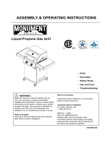
H Install Casters
[] Place the Cabinet Assembly (J) upside down and attach the
4 Casters to the Caster Seats. Use care to install each Caster
into the correct position.
Phillips Head Bolt: N6xS/8"
(with blue paint)
Qty: 16
Part # SB0027
©
Washer: M6
Qty: 16
Part # SB0005
Install Cabinet Front Crossbar and Firebox Supports
[] Attach the Cabinet Front Crossbar (L) to the Cabinet Assembly (3).
[] Attach the Firebox Supports to the Cabinet Assembly (3) on each side as
shown.
Phillips Head Bolt: M6x3/8"
Qty: 8
Part # SBO004
Washer: M6
Qty: 8
Part # SB0005
Firebox Support (L/R)
Qty: 4
Part # SAg015(L), SA9016( R )
This side is narrow
This Side is wider
11

Attach Door, Door Stopper, and Condiment Basket to Cabinet.
[] Attach Cabinet Door (K) to the Cabinet Assembly (J) using 4 Flat Head Bolts (M4x3/8").
[] Attach Magnetic Door Stopper to the Cabinet Assembly (J) left front frame using 2 Phillips
Head Bolts (M4x3/8").
[] Hang the Condiment Basket (M) inside of the Cabinet Door (K) as shown.
Flat Head Bolt: M4x3/8"
Qty: 4
Part # SB0029
Phillips Head Bolt: M4x3/8"
Qty: 2
Part # SB0060
Magnetic Door Stopper
Qty: 1
Part # SE0067
Install Firebox Assembly to Cabinet Assembly
[] Place the Firebox Assembly (A) on the Firebox Supports.
We recommend using 2 people to lift the Firebox Assembly (A).
[] Attach the Firebox Assembly to the Cabinet Assembly using
4 Phillips Head Bolts and 4 Washers.
Phillips Heat Bolt: M6x5/8"
Qty: 4
Part # SB0027
Washer: M6
Qty: 4
Part # SB0005
]2

Install Grease Tray and Grease Pan and Grease Pan Support
[] Slide the Grease Tray (S) along two sides of Firebox Assembly from the back of the Firebox
Assembly and stopped by two screws on the two sides of the cabinet.
[] Attach Grease Pan Support (H) to the Grease Tray, using 2 M5 Nuts, as shown.
[] Install the Grease Pan (I) into the Grease Pan Support (H), inserting it from the front of the
cabinet.
©
Nut: M5
qty: 2
Part # SB0019
Install Side Burner Control Panel to Side Burner Frame
[] Attach the Side Burner Control Panel (P) and Side Burner Front Bracket (q) to the
Side Burner Frame (B), using 3 Phillips Head Bolts and 3 Washers.
Phillips Head Bolt: M6x3/8"
Qty: 3
Part # SB0004
Washer: M6
Qty: 3
Part # SBO005
]3

Install Side Burner Assembly to Firebox Assembly.
[] Loosely screw 2 Phillips Head Bolts (M6x3/8") and 2 Washers into the upper left and
right corner holes in the left side of the firebox as shown in Inset 1. Leave 1/4" of the
bolts extending out of the firebox sides to attach the side burner brackets. Slide the Side
Burner Front and Rear Brackets over the heads of those bolts and tighten.
[] Use 2 Phillips Head Bolts (M6x3/8") and 2 Washers to attach the lower holes in the Side
Burner Front and Rear Brackets to the Firebox Assembly (A) as shown in Inset 2.
Inset i
Phillips Head Bolt: M6x3/8"
Qty: 4
Part # SB0004
Washer: M6
Qty: 4
Part # SBO005
Inset 2
Secure Side Burner Assembly to the Firebox Assembly.
[] Use 1 Phillips Head Bolt and 1 Washer from inside of
the firebox to secure attached Side Burner Assembly
as shown.
Phillips Head Bolt: M6x3/8"
qty: 1
Part # SB0004
Washer: M6
qty: 1
Part # SBO005
]4

Secure Side Burner Valve to Side Burner Control Panel
[] Insert the side burner valve stem up through the hole in the Side Burner Control Panel
(P). See Inset 1.
[] Insert side burner valve stem into the side burner tube. See Inset 2.
[] Secure the side burner valve to the Side Burner Control Panel (P) using 2 Phillips Head
Bolts. Ensure the side burner valve stem is centered in the stem tube of the side burner.
If not, center it, which may involve loosening the 2 Phillips Head Bolts. See Inset 3.
Phillips Head Bolt: M4x5/16"
Qty: 2
Part # SB0009D (White)
Inset 3
Inset 2
Inset 1
Attach Side Burner Control Panel to Firebox Assembly.
[] Use 1 Phillips Head Bolt (M4xS/16") to attach the Side Burner Control Panel (P)
to the Firebox Assembly (A) as shown.
Phillips Head Bolt: M4x5/16"
Qty: 1
Part # SB0009 (Black)
15

Secure Side Burner Control Knob to Side Burner Valve Stem and attach Side Burner
Ignition Wire,
[] Push the Control Knob onto the valve stem.
[] Slide the side burner ignition wire over the side burner igniter connector.
Control Knob
Qty: 1
Part # FE0015
Install Side Shelf Assembly
[] Attach the Side Shelf Control Panel (N) and Side Shelf Front Bracket (G) to the
Side Shelf Frame (C), using 3 Phillips Head Bolts and 3 Washers.
Phillips Head Bolt: M6x3/8"
Qty: 3
Part # SB0004
Washer: M6
Qty: 3
Part # SB0005
]6

_I Install Side Shelf Assembly to Firebox Assembly.
[] Loosely screw 2 Phillips Head Bolts (MBx3/8") and 2 Washers into the upper left and right
corner holes in the right side of the firebox as shown in Inset 1. Leave 1/4" of the bolts
extending out of the firebox sides to attach the side shelf brackets. Slide the Side Shelf
Front and Rear Brackets over the heads of those bolts and tighten.
[] Use 2 Phillips Head Bolts (M6x3/8") and 2 Washers to attach the lower holes in the Side
Shelf Front and Rear Brackets to the Firebox Assembly (A) as shown in Inset 2.
[] Use 1 Phillips Head Bolt ( M4x5/16" ) to attach the Side Shelf Control Panel (N) to Firebox
Assembly (A) as shown in Inset 3.
Phillips Head Bolt: M6x3/8"
Qty: 4
Part # SBO004
Washer: M6
Qty: 4
Part # SBO005
Phillips Head Bolt: M4x5/16"
Qty: 1
Part # SBO009 (Black)
Inset 1
Inset 3
Inset 2
_1_ Secure Side Shelf Assembly to the Firebox Assembly
[] Use 1 Phillips Head Bolt and 1 Washer from inside of firebox
to secure attached Side Shelf Assembly.
Phillips Head Bolt: M6x3/8"
Qty: 1
Part # SBO004
Washer : M6
Qty: 1
Part # SBO005
]?

Place Heat Diffusers, Cooking Grates, and Warming Rack into the Firebox Assembly
[] Place the Heat Diffusers (F) into the Firebox Assembly (A). Ensure the fronts of the Heat
Diffusers, marked "FRONT", are at the front of the firebox.
[] Place the Grates (E) into the Firebox Assembly (A). Each grate has a small knob on each
corner. The knobs should rest on the front or back panels of the firebox. The 2 small
and 1 large grates can be inserted in any order.
[] Place the Warming Rack (D) into the slots along the top of the Firebox Assembly (A) as
shown.
_1_ Place LP Cylinder into the Cabinet
[] Put the Cylinder Support Ring (R) into two holes in cabinet tubes, unhook the cylinder
support ring and hold at top of cabinet.
[] Place the LP cylinder down into the tank support hole in the bottom of the cabinet. Ensure
the valve faces to the front. Wrap the cylinder support ring around the top of the tank and
hook to secure the LP cylinder in place. See Inset 1.
[] Unscrew the bolt and nut on the left side cabinet panel and attached the left side cabinet
panel to Cylinder Support Ring using the unscrew bolt and nut. See Inset 2.
Ensure the regulator hose goes through the regulator hose support ring.
Do Not Hook Up the LP Cylinder to the Regulator Assembly at this time.
Inset 1
0
Cylinder Support Ring Regulator Hose Support Ring
]8

m
Install Battery and Utensil Hooks
[] Unscrew the electronic igniter cap. Place the "AA" Battery into the igniter with the
positive (+) end up. Screw the electronic igniter cap back into place. See Inset 1.
[] Insert the small end of the "S" Hooks into the holes on the end of the Side Shelf
Frame ( C ). See Inset 2.
Battery (Size AA)
Qty: 1
Part # SE0007
o
Inset 2
"S" Hooks
qty: 3
Part # SE9008
Inset 1
Congratulations - Assembly is now Complete
[] Remove any additional labels or packing material from the grill except the CSA label.
Be sure to clean all foam packing material out of all areas.
[] Please proceed to and read the remaining sections of the Operator's Manual prior to
hooking up your LP cylinder or operating your grill.
O
@ @.@ @
]9

CORRECT LP GAS TANK USE
[] LP gas grill models are designed for use with a
standard 20 lb. (9.1kg)Liquid Propane Gas (LP
Gas) tank, which is not included with the grill.
Never connect your gas grill to an LP gas tank that
exceeds this capacity. A tank of approximately 12"
(305mm) in diameter by 18-1/2"(472mm) high is
the maximum size LP gas tank to use. You must
use an "OPD" gas tank which offers a listed Overfill
Prevention Device. This safety feature prevents
tanks from being overfilled which can cause
malfunction of the LP gas tank, regulator and grill.
[] The LP gas tank must be constructed and marked in
accordance with the Specifications for LP-Gas
Cylinders of the U.S. Department of Transportation
(D.O.T.) or the National Standard of Canada,
CAN/CSA-B339, Cylinders, Spheres and Tubes for
Transportation of Dangerous Goods; and
Commission, as applicable.
[] The LP gas tank must have a shutoff valve
terminating in a LP gas supply tank valve outlet
that is compatible with a Type 1 tank connection
device. The LP gas tank must also have a safety
relief device that has a direct connection with the
vapor space of the tank.
[] The tank supply system must have a means for
vapor withdrawal.
[] The LP gas tank used must have a collar to protect
the tank valve.
[] Never connect an unregulated LP gas tank to your
gas grill. The gas regulator assembly supplied with
your gas grill is adjusted to have an outlet pressure
of 11"water column (W.C.) for connection to an LP
gas tank. Only use the regulator and hose
assembly supplied with your gas grill.
Replacement regulators and hose assemblies
must be those specified by Sears. See the Parts
List.
[] Have your LP Gas dealer check the release valve
after every filling to ensure it remains free of
defects.
[] Always keep the LP gas tank in an upright position.
Do not subject the LP gas tank to excessive heat.
[] Never store an LP gas tank indoors. If you store
your gas grill indoors, always disconnect the LPgas tank
first and store it safely outside.
[] LP gas tanks must be stored outdoors in a
well-ventilated area and out of the reach of
children.
[] Disconnected LP gas tanks must not be stored in a
building, garage, or any other enclosed area.
[] The regulator and hose assembly can be seen after
opening the door (if applicable) and must be
inspected before each use of the grill. If there is
excessive abrasion or wear or if the hose is cut, it
must be replaced prior to using the grill again.
[] Never light your gas grill with the lid closed or
before checking to ensure the burner tubes are
fully seated over the gas valve orifices.
[] Never allow children to operate your grill. Do not
allow children or pets to play near your grill.
2O
[]
[]
Use of alcohol or drugs may impair the ability
to assemble and operate the appliance.
Keep a fire extinguisher readily accessible. In
the event of an oil or grease fire, do not attempt
to extinguish with water. Use a type B extinguisher
or smother with dirt, sand, or baking soda.
[] In the event of rain, cover the grill and turn off
the burner and gas supply.
[] Use your grill on a level, stable surface and ensure
the locking casters are locked before use.
[] Do not leave the grill unattended when in use.
[] Do not move the appliance when in use.
[] Allow the grill to cool before moving or storing.
[] Do not use your grill as a heater.
[]
This grill is not intended to be installed in or on
recreational vehicles and/or boats.
A. Do not store a spare LP gas tank under or
near this appliance.
B. Never fill the tank beyond 80 percent full;
C. If the information in "(a)"and "(b)" is not
followed exactly, a fire causing death or
serious injury may occur.
• Use your grill at least 2 feet away from
any wall or surface. Use your grill at
least 2 feet away from combustible objects
that can melt or catch fire (such as vinyl or
wood siding, fences and overhangs) or
sources of ignition including pilot lights on
water heaters and live electrical appliances.
• Never use your gas grill in a garage, porch,
shed, breezeway, or any other enclosed area.
• Never obstruct the flow of ventilation air
around your gas grill housing.
/