
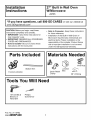
Installation
nstruct=ons
27" Built In Wall Oven
W/Microwave
JKP85
"lf you have questions, call 800-GE-CARES orvisit our website at I
www.GEAppliances.com"
I
CAUTION: Before you begin- read these
instructions completely and carefully.
• IMPORTANT- Save these instructions for
local inspector's use.
• IMPORTANT-OBSERVEALL GOVERNING
CODES AND ORDINANCES.
• Note to Installer- Be sure to leave these
instructions with the Consumer.
• Note to Consumer- Keep these instructions
for future reference.
• Installation of this Built-In Wall Oven w/
Microwave requires basic mechanical and
electrical skills. Proper installation is the
responsibility of the installer. Product failure
due to improper installation is not covered
under the GE Applicance Warranty.
Parts Included
8 screws (double)
Bottom Trim
Materials Needed
[_r_ Wire N_uts
Junction _
Strain Relief Box
Clamp 36" of String
Tools You Will Need
1/8" Drill Bit & Phillips
Electric or Screwdriver
Hand Drill
Pub. No. 31-10462
229c4053P430 1

Installation Instructions
IMPORTANT SFETY INSTRUCTIONS
For Your Safety
• Be sure your oven is installed properly by a
qualified installer or service technician.
• Be sure the oven is securely installed in a
cabinet that is firmly attached to the house
structure. Weight on the oven door could
cause the oven to tip and result in injury.
Never allow anyone to climb, sit, stand or
hang on the oven door.
• Make sure the cabinets and wall coverings
around the oven can withstand the
temperatures (up to 200°R) generated by the
oven.
,_ CAUTION: The electrical power
to the oven supply line must be
shut off while line connections
are being made. Failure to do so
could result in serious injury or death.
Electrical
Requirements
This appliance must be supplied with the
proper voltage and frequency, and connected
to an individual properly grounded branch
circuit, protected by a circuit breaker or fuse
having amperage as noted on rating plate.
(Rating Plate is located on the wall inside the
microwave oven.)
We recommend you have the electrical wiring
and hookup of your oven connected by a
qualified electrician. After installation, have the
electrician show you where your main oven
disconnect is located.
Check with your local utilities for electrical
codes which apply in your area. Failure to wire
your oven according to governing codes could
result in a hazardous condition. If there are not
local codes, your range must be wired and
fused to meet the requirements of the National
Electrical Code, ANSI/NFPA No. 70-Latest
Edition. You can get a copy by writing:
National Fire Protection Association
Battery March Park
Quincy, MA 02269
Effective January 1, 1996, the National
Electrical Code requires that new, but not
existing, construction utilize a 4 conductor
connection to an electric range. When
installing an electric range in new construction,
follow the instructions in NEW
CONSTRUCTION AND FOUR CONDUCTOR
BRANCH CIRCUIT CONNECTION.
You must use a three-wire, single-phase AC
208Y/120 Volt or 240/120 Volt, 60 hertz
electrical system. If you connect to aluminum
wiring, properly installed connectors approved
for use with aluminum wiring must be used.
2

Installation Instructions
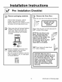
Pre-Installation Checklist
Remove packaging materials.
Check inside microwave, behind
hinges, and under false bottom.
Remove labels on door, plastic on trims
and panel, and all tape around oven.
Open oven door and remove literature
prepack, broiler pan and grid, and
oven racks. Open microwave door
and remove shelves and turntable
package.
E_, Remove Installation Instruction from
literature prepack and read them
carefully before you begin.
Be sure to place all literature, Use and
Care, Installations, etc. in a safe place
for future reference.
E_ Remove the Oven Door
Open the oven door to the stop broil position.
i[ DO NOT LIFT THE i
DOOR BY THE
HANDLE!
E_ Grasp the door on both sides and lift
up and off the hinges.
NOTE:The oven door is very
heavy. Be sure you have a
firm grip before lifting the
oven door off the hinges. Use
caution once the door is
removed. Do not lay the door
on its handle. This could
cause dents or scratches.
I_ Cover hinge with paper towel
rolls or toweling.
CAUTION: When the door is
removed and the hinge arms are at
the stop postion, DO NOT bump or
try to move the hinge arms. The
hinges could snap back causing an
injury to the hands. Cover the
hinges with toweling or empty
towel rolls while working in the
oven area.
3 (Continued on following page)

Installation Instruction
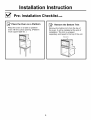
[_ Pre-Installation Checklist cont.
[_" Place the Oven Platform
on a
Place the oven on a table or platform
even with the cutout opening. (Platform
must support 225 Ibs. )
1 jz ii
I_' Remove the Bottom Trim
Remove the bottom trim from the top of
the oven. It will be installed at the end of
installation. The trim is wrapped
separately and taped to the top of the unit.
Bottom Trim
4

Installation Instructions
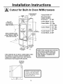
Cutout for Built-In Oven W/Microwave
Allow 7/8"
for overlap of
oven over side ....
edges of cutout_
Allow a minimum of 20"
for clearance to adjacent
corners, drawers, walls, etc.
when doors are open
CABINET
27"
CUTOUT
WIDTH
25" MIN.
25 1/4" MAX.
2" x 4"
or _
equivalentt
runners
JUNCTION BOX
LOCATION
CUTOUT _[
HEIGHT 48"
41 1/8" MIN.
MAX. TO bottom
of junction box
Alternate
junction box
location
Cabinet Width 27"
Recommended
Cutout Location
From Floor ..... 21 5/8"
Cutout Depth .23 1/2"
Cutout Width ..25" Min.
........................ 25 1/4" Max.
Cutout Height 41 1/8" Min.
........................ 41 1/4" Max.
Overall Height 41 5/8"
Overall Width .. 26 5/8"
Allow 1" for
overlap of oven
top and bottom
of cutout
Recommended
cutoutlocation
floor
21 5/8"
If the cabinets do not have a solid bottom, then
two braces or runners must be installed to
support the weight of the oven. The runners
and braces must support 275 pounds.
NOTE: If the cabinet does not have
a front frame and the sides are
less than 3/4" thick, shim both
sides equally to establish the
cutout width.
i
L_
_27"
2"x4"or
Equivalent
Runners
lm
NOTE: If using equivalent
runners, then the center
of the equivalent runners
should be 20 112".

Installation Instructions
Electrical Connections
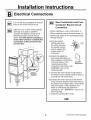
Turn off the circuit breaker or remove
fuses to the oven branch circuit.
With the oven in front of the cabinet
opening on a table or platform,
connect the flexible conduit to the
electrical junction box as shown
below. You will need to purchase a
strain relief clamp to complete the
connection of the conduit to the
junction box.
STRAIN RELIEF CLAMP
( NOT iNCLUDED }
MUST BE USED
New Construction and Four-
Conductor Branch Circuit
Connection
• When installing in a new construction, or
• When installing oven in a mobile home, or
• When local codes do not permit grounding
through neutral:
a. Cut the neutral
(White) lead from
the crimp. Re-strip
the neutral (white)
lead to expose the
proper length of
conductor.
b.Attach the appliance
grounding lead (green or
bare copper)in accordance
with local codes. If the
residence grounding
conductor is aluminum, see
WARNING note on the
following page.
_, Ground
Wires
Junction
Box Cover
c. Connect the oven neutral (white) lead to
the branch circuit neutral (white or gray) in
accordance with local codes.
d. Connect the oven red lead to the branch
circuit red lead and the oven black lead to
the branch circuit black lead in accordance
with local codes. If the residence red,
black or white leads are aluminum
conductors, see" WARNING" note on the
following page.
e. Install the Junction Box Cover.
OR
6 (Continued on following page)

Installation Instructions
Electrical Connections cont
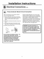
Three-Conductor Branch Circuit Connection
When connecting to a 3-conductor branch
circuit, if local codes permit:
a. Connect the bare oven ground conductor
with the crimped neutral (white) lead to the
branch circuit neutral (white or gray in
color).
b. The oven red lead to the branch circuit red
lead.
c. The oven black lead to the branch circuit
black lead in accordance with local codes.
d. Install Junction Box Cover.
Junction Box
Cover
NOTE TO ELECTRICIAN: The 3 power leads
supplied with this appliance are UL recognized
for connection to larger gauge household wiring.
The insulation of these 3 leads is rated at
temperatures much higher than the temperature
rating of household wiring. The current carrying
capacity of the conductor is governed by the
temperature rating of the insulation around the
wire, rather than the wire gauge alone.
WARNING: Improper connection of
aluminum house wiring to copper leads
can result in an electrical hazard or fire.
Use only connectors designed for joining
copper to aluminum and follow the
manufacturer's recommended procedure
closely.
i
Do not shorten this flexible conduit. The
conduit strain relief clamp must be
securely attached to the junction box and
the flexible conduit must be securely
attached to the clamp. If the flexible
conduit will not fit within the clamp, do
not install the oven until a clamp of the
proper size is obtained.
7

Installation Instructions
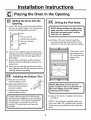
Placing the Oven In the Opening
Sliding the Oven Into the
Opening.
a. Loop a 36" string around the conduit before
the oven is slid into place. This will keep the
conduit from falling behind the oven.
L
Pull out on the
string while pushing
_ the oven into the
cabinet.
<:4
b. Lift oven into cabinet cutout using the oven
opening as an grip. Carefully push against
oven front frame. Do not push against out-
side edges.
c. As the oven is slid back, pull the string so
that the conduit will lie behind the oven in a
natural loop.
d. When you are sure the conduit is out of the
way, slide the oven 3/4 the way back into the
opening. Remove the string.
a. Slide the oven 3/4 way
into the cabinet cutout.
b. Attach the bottom trim to
the front frame with the 3
screws provided.
c. Slide the oven all the way
into the cabinet cutout.
Installing the Bottom Trim
Caution: Be sure you do not tip the oven
foward during installation or you may bend
the bottom trim. The bottom trim provides
an opening for cooling air to enter the
cabinet. This opening should never be
blocked.
Drilling the Pilot Holes
NOTE: Before drilling the pilot holes,
make sure the oven is pushed as far
back into the opening as it will go,
and that it is centered.
a. Drill four-I/8" pilot holes through the
mounting holes (top and bottom) of the
side trim, for the four #8 screws provided.
MOUNTING HOLE LOCATIONS
The screws must
be a minimum of
1/4" from the front
edge of the
cutout.
NOTE: Mounting screws must be
used. Failure to do so could result in
the oven falling out of the cabinet
causing serious injury.
i
b. Secure the Oven to Cabinet with screws
provided.
NOTE: If the cabinet is particle board, you
must use 4 #8 x 3/4" particle board screws.
These may be purchased at any hardware
store.
8

Installation Instructions
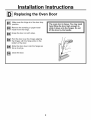
_ Replacing the Oven Door
Make sure the hinge is in the door stop
position.
Remove the toweling or paper towel
holder from the hinge.
Grasp the door on both sides.
Hold the door over the hinges aligning
the hinges with the hinge slots on the
bottom of the door.
Slide the door down onto the hinges as
far as it will go.
I_1 Close the door.
The oven door is heavy. You may need
help lifting the door high enough to
slide it down onto the hinges. Do not
lift the door by the handle.
9

Installation Instruction
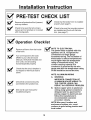
PRE-TEST CHECK LIST
Check that the bottom trim is installed
Remove all
protective
film if
present,
and any stickers. _ properly (see page 7).
checkt°besurethata''w'rin°is
secure and not pinched or in contact
with moving parts.
Check to be sure the mounting screws
are installed and flush with the side
trim, (see page 7).
_ Operation Checklist
[_ Remove all items from the inside 1li_Vl
of the oven.
Turn on the power to the oven.
(Refer to your Use and Care
Manual.) Verify that the bake and
broil units, and all cooking
functionsoperate properly.
Check that the circuit breaker is
not tripped or the house fuse is
blown.
i_ heck that conduit is securely
connected to the junction box.
[_ See Use & Care manual for
troubleshooting list.
NOTE TO ELECTRICIAN:
The power leads supplied with this
appliance are UL recognized for
connections to larger gauge
household wiring. The insulation of
these leads is rated at temperatures
much higher than the temperature
rating of household wiring. The
current carrying capacity of a
conductor is governed by the wire
gauge and also the temperature rating
of the insulation around the wire.
NOTE: ALUMINUM WIRING
A. WARNING:
IMPROPER CONNECTION OF
ALUMINUM HOUSE WIRING TO
THE COPPER LEADS CAN
RESULT IN A SERIOUS PROBLEM.
B. Splice copper wires to aluminum
wiring using special connectors
designed and UL approved for
joining copper to aluminum and
follow the manufacturer's
recommended connector
procedure closely.
NOTE:Wire used, location and
enclosure of splices, etc., must
conform to good wiring practice and
local codes.
10

NOTES
11

NOTES
Pub. No. 31-462
12 229c4053P430
-
 1
1
-
 2
2
-
 3
3
-
 4
4
-
 5
5
-
 6
6
-
 7
7
-
 8
8
-
 9
9
-
 10
10
-
 11
11
-
 12
12


Ask a question and I''ll find the answer in the document
Finding information in a document is now easier with AI
Related papers
-
GE JKP85BABB Installation guide
-
GE ZEK938SF5SS Installation guide
-
GE JKP48WF1WW Installation guide
-
GE JTP85WAWW Installation guide
-
-
GE ZET938WF3WW Installation guide
-
GE JKP86BF1BB Installation guide
-
GE PT970WM1WW Installation guide
-
GE JTP86SF1SS Installation guide
-
Other documents
-
Kenmore 91147704200 Installation guide
-
Unbranded 165-SSCHFO-50 Operating instructions
-
Everbilt 165-SCH-FO-40 Installation guide
-
Summit SEW24SS Installation guide
-
-
Gianni Industries GL-80F Installation guide
-
GE Profile PT9800SHSS Installation guide
-
Kenmore 91147759200 Installation guide
-
Yes CTS70DP2NS1 Installation guide
-
 GE Monogram ZET1SHSS DL c3d43127eaf03e7a0c3bc9a37494
