DFI EC531-KH/EC532-KH Installation Guide User manual

Type
User manual

This manual is also suitable for

1
EC531-KH/EC532-KH Installation Guide
Package Contents
1 EC531-KH/EC532-KH system unit
• 1 Quick Installation Guide
1 CD disk includes:
- Drivers / Manual
Notes:
1. This port can be in HDMI or DVI-D (DVI available upon request).
2. This port is a DP/HDMI combo port but can only transmit either HDMI or DP signals (as indicated on
the panel). Please plug in a DP or an HDMI cable with the right orientation and alignment to avoid
damage to the connector. You should feel resistance (due to a pin on the right) if the cable is not
inserted correctly. For detailed instructions, see https://youtu.be/SUj07rfN5l8.
www.d.com
DC-in
DVI-I
(1)
(DVI-D signal)
HDMI
(2)
USB 3.0
LAN 1
LAN 2
USB 3.0
SATA 1 SATA 2
VGA
COM 3
COM 4
COM 5
Line-out
Microphone
Expansion slots
DIO COM6 COM7 COM8
Front View
Rear View
COM 2 COM 1
Remote Power Switch
USB 2.0
Status LED
HDD LED
Reset Switch
Power Button
DFI reserves the right to change the specications at any time prior to the product's release. For the latest revision and details of the
installation process, please refer to the user's manual.
2
Installing a 2.5" SATA Drive
The SATA drive bay can be easily accessed witout opening the system. However,
the system does not support hot-swapping hard drives; turn off the system rst
before proceeding with the following procedure for installing a SATA drive.
1. Locate the drive bay on the front panel and open it by releasing the handle.
2. Slide the HDD into the drive bay. Note that the HDD should be positioned
vertically with the SATA power connector on top of the data connector to
correctly engage with the system's SATA connectors. Then close the drive bay
and lock the handle.
SATA power/data cable
SATA power
Connecotr
Drive bay handle
SATA drive bay
SATA 1 SATA 2
Notes:
1. The slot is desgined to exactly t a 2.5" SATA drive with 7mm thickness; it
cannot t SATA drives with other sizes.
2.
Do not force to close the drive bay if the HDD is not correctly inserted.
3
Installing a SODIMM
1. The SODIMM sockets are located on the system board. You need to revmove
the system cover first. Before working inside your system, observe the
following precautions:
(1) Make sure the system and all other peripherals connected to it have been
powered off.
(2) Disconnect all power cords and external cables.
2. The 4 mounting screws on the bottom of the system are used to secure the
cover to the chassis. Remove these screws and put them in a safe place for
later use.
3. The SODIMM sockets are under the supporting bracket.
Mounting screw
SODIMM sockets
Supporting bracket
4
To install a SODIMM module, grasp the module by its edges and align the
module’s notch with the socket’s notch; then insert the module into the socket at
an angle and push it down until you feel a click.
Notes:
1. The system supports dual-channel conguration. To enable dual-channel, populate
both SODIMM sockets.
2. The SODIMM sockets can only accept DDR4 memory modules (Skus with Intel
®
CM238 chipset support ECC). Please do not install other types of memory modules.
SODIMM module
5
Installing a Mini PCIe Card
The system board is equipped with 2 Mini PCIe slots with Mini SIM card sockets to
support a variety of wireless LAN and mobile broadband communication modules.
Mini PCIe slot 1 provides both USB and PCIe interfaces whereas Mini PCIe slot 2
provides only USB interface.
1. Grasp the Mini PCIe card by its edges and align the notch in the connector of
the Mini PCIe card with the notch in the connector on the system board.
2. Push down the other end of the card and secure it on the board with the
provided mounting screw.
Mini PCIe 1
Mini PCIe 2
Mounting screw
6
Installing a SIM Card
Open the SIM card socket by pushing the white latch inward.
Insert the SIM card into the slot. Please place the card with the IC facing down
and the angled corner aligning with the socket's angled corner so it will be cor-
rectly in contact with the system board.
Close the slot's cover and lock the slot by pushing the white latch outward.
Flip the cover up to open it
Close the cover and lock it
Push the latch
inward to open it
SIM 2
7
Installing an M.2 Card
To install an M.2 card, insert the bottom edge of the M.2 card into the connector, and then secure
the card to the standoff with the provided mounting screw.
The onboard M.2 Type 2280 connector (M Key) supports PCIe NVMe modules up to PCIe Gen 3.0
x4 bandwidth. Note that only SKUs with Intel
®
QM175 Chipset support M.2 socket.
M.2 Slot
Mounting screw
8
Installing a PCI or PCIe Expansion Card
Important:
When inserting expansion cards into the system unit, please select a standard card
within 190mm (as shown in the picture below) in order to t expansion slots.
1. PCI and PCIe slots on the riser card inside the system are used to install
expansion cards. To install an expansion card, you need to rst remove the slot
plates and bracket by uninstalling the mounting screws on the rear chassis.
Slot plate
Mounting screw and bracket
9
2. Insert the expansion card into a PCI or PCIe slot on the riser card and secure
the bracket in place.
Rear View
PCIe card
Note:
The EC531-KH has one PCIe x16 slot and two PCI slots with the H320-2P1E card, whereas
the EC532-KH has one PCI slot and two PCIe x16 slots with the H320-1P2E card.
10
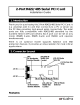
Board Layout and Jumper Settings
Buzzer
USB 3/4
USB 3.0
USB 1/2
USB 3.0
STB_LED
PWR_BTN_1
HDMI (default)/DP
DVI
1
-
DC-in
GLAN 2
GLAN 1
PCIe x16 (PCIE1)
SPI Flash
BIOS
1
2 10
9
9
USB 13/14
1
2 10
COM 4
VGA
Clear CMOS
Data (JP1)
PS/2 Power Select
(JP14)
6
(JP13) (JP19)
1
6
6
1
(JP12) (JP18)
1
6
6
1
1
2 10
COM 3
1
(JP10)
6
6
9
1
2 10
COM 2
9
1
2
(JP11) (JP17)
6
6
1
2
1
2 10
COM 1
9
1
2
16
1
4-pin power
1
2
3
4
JP8
1
6
1
(JP5)
6
2
1
(JP6)
6
2
JP7
COM 5
1
2 10
9
COM 6
1
2 10
9
21
(JP4)
PCIe x4 (PCIE2)
Reset
DDR4_1 SODIMM
DDR4_2 SODIMM
1
(JP9)
6
6
1
1
2
1
12
6
1
4
SATA Power
1
4
Power Button
Power LED
HDD LED
M.2 Type 2280
(PCIe)
LPC
1
2
14
1
1
DIO Power
DIO
EXC
+
SATA 3.0
USB 11-12
USB 2.0
USB 2.0
USB 9
(JP16)
1
1
(JP15)
1
SATA 0
SATA 1
1
SIM
Mini PCIe 1
1
bettery
1
1
1
USB 2.0
SIM
Mini PCIe 2
COM 2
COM 1
Front Audio
2
1
10
9
1
2 1
29
30
LVDS LCD
Panel
JP2
JP3
51
Front Panel
13
1
10
Clear CMOS Data JP1
Normal (default) 1-2 On
Clear CMOS Data 2-3 On
PS/2 KB/MS Power source JP14
5V 1-2 On
5V_Standby 2-3 On
DIO bit 4~7 Pull-up/Pull-down Selection JP2
Pull-up
5V/5V_Standby
1-2 On
Pull down GND 2-3 On
DIO bit 0~3 Pull-up/Pull-down Selection JP3
Pull-up
5V/5V_Standby
1-2 On
Pull down GND 2-3 On
DIO bit 0~7 Power Source selection JP4
5V_Standby 1-2 On
5V 2-3 On
RS232/Power Select: COM 1 (JP8), COM 2 (JP7)
RS232 (default) 1-3 (RI), 2-4 (DCD) On
RS232 with power 3-5 (+5V), 4-6 (+12V) On
RS232/422/485 Select: COM 1 (JP10), COM 2 (JP16)
COM 3 (JP13), COM 4 (JP5)
RS232 (default) 1-3, 4-6 On
RS422 Full Duplex 3-5, 4-6 On
RS485 3-5, 2-4 On
RS232/422/485 Select:
COM 1 (JP9/JP15), COM 2 (JP11/JP17)
COM 3 (JP12/JP18), COM 4 (JP6/JP19)
RS232 (default) 1-3, 2-4 On
RS422 Full Duplex/RS485 3-5, 4-6 On
Notes:
1. When COM1 RS232/422/485 is selected, JP9 and JP15 must
be set in accordance to JP10.
2. When COM2 RS232/422/485 is selected, JP11 and JP17
must be set in accordance to JP16.
3. When COM3 RS232/422/485 is selected, JP12 and JP18
must be set in accordance to JP13.
4. When COM4 RS232/422/485 is selected, JP6 and JP19 must
be set in accordance to JP5.
11
A55502934
RS232/Power Select:
COM 6 (JP7), COM 7 (JP11)
RS232 (default) 1-3 (RI), 2-4 (DCD) On
RS232 with power 3-5 (+5V), 4-6 (+12V) On
RS232/422/485 Select:
COM 6 (JP1), COM 7 (JP8)
RS232 (default) 1-2 On
RS422 Full Duplex 3-4 On
RS485 5-6 On
RS232/422/485 Select:
COM 6 (JP2/JP3), COM 7 (JP9/JP10)
RS232 (default) 1-3, 2-4 On
RS422 Full Duplex/RS485 3-5, 4-6 On
RS232/422/485 Select:
COM 8 (JP13/JP14)
RS232 (default) 1-3, 2-4 On
RS422 Full Duplex/RS485 3-5, 4-6 On
RS232/422/485 Select:
COM 8 (JP12)
RS232 (default) 1-2 On
RS422 Full Duplex 3-4 On
RS485 5-6 On
1
6
(JP7)
1
6
(JP2)
1
6
(JP3)
1
6
(JP1)
1
6
(JP5)
1
6
(JP6)
1
6
(JP4)
1
6
(JP11)
1
6
(JP9)
1
6
(JP10)
1
6
(JP8)
1
6
(JP13)
1
6
(JP14)
1
6
(JP12)
DC-in
USB 3.0
USB 7-8
USB 5-6
DIO COM6 COM7
COM8
I/O board
Notes:
1. When COM 6 RS232/422/485 is selected,
JP2 and JP3 must be set in accordance to JP1.
2. When COM 7 RS232/422/485 is selected,
JP9 and JP10 must be set in accordance to JP8.
3. When COM 8 RS232/422/485 is selected,
JP13 and JP14 must be set in accordance to JP12.
  • Page 1 1
  • Page 2 2
  • Page 3 3
  • Page 4 4
  • Page 5 5
  • Page 6 6
  • Page 7 7
  • Page 8 8
  • Page 9 9
  • Page 10 10
  • Page 11 11

DFI EC531-KH/EC532-KH Installation Guide User manual

Type
User manual
This manual is also suitable for

Ask a question and I''ll find the answer in the document

Finding information in a document is now easier with AI