Allied 4AC16LT Installation guide
- Category
- Split-system air conditioners
- Type
- Installation guide

506467-01 Page 1 of 19Issue 1946
Save these instructions for future reference
INSTALLATION INSTRUCTIONS
4AC16LT SERIES
Two-Stage Split System Air Conditioner
(P) 506467-01
*P506467-01*
Manufactured By
Allied Air Enterprises LLC
A Lennox International, Inc. Company
215 Metropolitan Drive
West Columbia, SC 29170
This manual must be left with the homeowner for future reference.
This is a safety alert symbol and should never be ignored. When you see this symbol on labels or in manuals, be alert to
the potential for personal injury or death.
Installation and servicing of air conditioning equipment
can be hazardous due to internal refrigerant pressure
and live electrical components. Only trained and
qualied service personnel should install or service
this equipment. Installation and service performed by
unqualied persons can result in property damage,
personal injury, or death.
WARNING
ELECTRICAL SHOCK HAZARD!
Risk of electrical shock. Disconnect all
remote power supplies before installing
or servicing any portion of the system.
Failure to disconnect power supplies
can result in property damage, personal
injury, or death.
WARNING
Sharp metal edges can cause injury. When installing
the unit, use care to avoid sharp edges.
WARNING
Table of Contents
General ........................................................................1
Installation ...................................................................2
Refrigeration Piping .....................................................4
Electrical Wiring .........................................................12
Start-Up .....................................................................13
Operation ...................................................................14
Maintenance ..............................................................17
Homeowner Information ............................................18
General
Read this entire instruction manual, as well as the
instructions supplied in separate equipment, before
starting the installation. Observe and follow all warnings,
cautions, instructional labels, and tags. Failure to comply
with these instructions could result in an unsafe condition
and/or premature component failure.
These instructions are intended as a general guide only
for use by qualied personnel and do not supersede any
national or local codes in any way. The installation must
comply with all provincial, state, and local codes as well as
the National Electrical Code (U.S.) or Canadian Electrical
Code (Canada). Compliance should be determined prior
to installation.
This unit uses R-410A, which is an ozone-friendly HFC
refrigerant. The unit must be installed with a matching
indoor coil and line set. A lter drier approved for use with
R-410A is installed in the unit.

Page 2 of 19 506467-01Issue 1946
When servicing or repairing HVAC components, ensure
the fasteners are appropriately tightened. Table 1 shows
torque values for fasteners.
Fastener Torque
Stem Caps 8 ft. lbs.
Service Port Caps 8 ft. lbs.
Sheet Metal Screws 16 in. lbs.
#8 Machine Screws 16 in. lbs.
#10 Machine Screws 28 in. lbs.
Compressor Bolts 90 in. lbs.
Table 1. Torque Table
Inspection of Shipment
Upon receipt of equipment, carefully inspect it for possible
shipping damage. If damage is found, it should be noted
on the carrier’s freight bill. Take special care to examine
the unit inside the carton if the carton is damaged. Any
concealed damage discovered should be reported to the
last carrier immediately, preferably in writing, and should
include a request for inspection by the carrier’s agent.
If any damages are discovered and reported to the carrier
DO NOT INSTALL THE UNIT, as claim may be denied.
Check the unit rating plate to conrm specications are as
ordered.
Safety Precautions
Follow all safety codes. Wear safety glasses and work
gloves. Use quenching cloth for brazing operations.
Have re extinguisher available. Read these instructions
thoroughly and follow all warning or cautions attached to
the unit.
1. Always wear proper personal protection equipment.
2. Always disconnect electrical power before removing
panel or servicing equipment.
3. Keep hands and clothing away from moving parts.
4. Handle refrigerant with caution; refer to proper MSDS
from refrigerant supplier.
5. Use care when lifting, avoid contact with sharp edges.
Installation
NOTE: In some cases, noise in the living area has been
traced to gas pulsations from improper installation of
equipment.
• Locate unit away from windows, patios, decks, etc.
where unit operation sounds may disturb customer.
• Leave some slack between structure and unit to
absorb vibration.
• Place a sound-absorbing material, such as Isomode,
under the unit if it will be installed in a location or
position that will transmit sound or vibration to the
living area or adjacent buildings.
• In heavy snow areas, do not locate the unit where
drifting snow will occur. The unit base should be
elevated above the depth of average snows.
NOTE: Elevation of the unit may be accomplished
by constructing a frame using suitable materials. If a
support frame is constructed, it must not block drain
holes in unit base.
• When installed in areas where low ambient
temperatures exist, locate unit so winter prevailing
winds do not blow directly into outdoor coil.
• Locate unit away from overhanging roof lines which
would allow water or ice to drop on, or in front of, coil
or into unit.
When outdoor unit is connected to factory-approved indoor
unit, outdoor unit contains system refrigerant charge for
operation with matching indoor unit when connected by 15
ft. of eld-supplied tubing. For proper unit operation, check
refrigerant charge using charging information located on
control box cover.
Outdoor Section
Zoning ordinances may govern the minimum distance the
condensing unit can be installed from the property line.
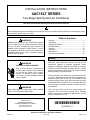
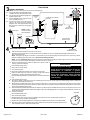
Install on a Solid, Level Mounting Pad
The outdoor section is to be installed on a solid foundation.
This foundation should extend a minimum of 2” (inches)
beyond the sides of the outdoor section. To reduce the
possibility of noise transmission, the foundation slab
should NOT be in contact with or be an integral part of the
building foundation. See Figure 1.
If conditions or local codes require the unit be attached to
pad or mounting frame, tie down bolts should be used and
secured to unit base pan.

506467-01 Page 3 of 19Issue 1946
Discharge Air
Mounting Slab
Ground Level
Building
Structure
Mounting slab must slope slightly away from
building, not to exceed 1/4” per foot.
Figure 1. Slab Mounting
Elevate Unit
Accumulation of water and ice in base pan may cause
equipment damage.
CAUTION
Elevate unit per local climate and code requirements to
provide clearance above estimated snowfall level and
ensure adequate drainage of unit. Use snow stand in areas
where prolonged freezing temperatures are encountered.
If conditions or local codes require the unit be attached to
pad or mounting frame, tie down bolts should be used and
fastened through knockouts provided in unit base pan.
Clearance Requirements
When installing, allow sucient space for airow clearance,
wiring, refrigerant piping, and service. For proper airow,
quiet operation and maximum eciency. Position so water,
snow, or ice from roof or eaves cannot fall directly on unit.
Refer to Table 2 for installation clearances.
Location Minimum Clearance
Service box 30”
Top of unit* 48”
Between units 24”
Against wall 6”
* Maximum sot overhang is 36”.
NOTE: At least one side should be unobstructed by a wall or
other barrier.
Table 2. Clearances
30” around
Control
Box
24”
6”*
NOTE: See Table 2 for specific minimum
clearance guidelines.
Figure 2.
DO LOCATE THE UNIT:
• With proper clearances on sides and top of unit
• On a solid, level foundation or pad (unit must be level
to within ± 1/4 in./ft. per compressor manufacturer
specications)
• To minimize refrigerant line lengths
DO NOT LOCATE THE UNIT:
• On brick, concrete blocks or unstable surfaces
• Near clothes dryer exhaust vents where debris
accumulates
• Near sleeping area or near windows
• Under eaves where water, snow or ice can fall directly
on the unit
• With clearance less than 2 ft. from a second unit
• With clearance less than 4 ft. on top of unit
Rooftop Installations
Install unit at a minimum of 6” above surface of the roof
to avoid ice buildup around the unit. Locate the unit
above a load bearing wall or area of the roof that can
adequately support the unit. Consult local codes for rooftop
applications.
If unit cannot be mounted away from prevailing winds, a
wind barrier should be constructed. Due to variation in
installation applications, size and locate barrier according
to the best judgment of the installer.

Page 4 of 19 506467-01Issue 1946
Refrigeration Piping
• Use only refrigerant grade copper tubes.
• Split systems may be installed with up to 50 feet of
line set (no more than 20 feet vertical) without special
consideration (see long line set guidelines).
• Ensure that vapor and liquid tube diameters are
appropriate to capacity of unit.
• Run refrigerant tubes as directly as possible by
avoiding unnecessary turns and bends.
• When passing refrigerant tubes through the wall, seal
opening with RTV or other silicon-based caulk.
• Avoid direct tubing contact with water pipes, duct work,
oor joists, wall studs, oors, walls, and any structure.
• Do not suspend refrigerant tubing from joists and
studs with a rigid wire or strap that comes in direct
contact with tubing.
• Ensure that tubing insulation is pliable and completely
surrounds vapor tube.
It is important that no tubing be cut or seals broken until you
are ready to actually make connections to the evaporator
and to the condenser section. DO NOT remove rubber
plugs or copper caps from the tube ends until ready to
make connections at evaporator and condenser. Under no
circumstances leave the lines open to the atmosphere for
any period of time, if so unit requires additional evacuation
to remove moisture.
Table 3. Refrigerant Line Set Diameters (in.)
Liquid Line
Btuh
Line Set Length and Size
12 ft. 25 ft. 50 ft. 75 ft. 100 ft.
24,000 3/8 3/8 3/8 3/8 3/8
36,000 3/8 3/8 3/8 3/8 1/2
48,000 3/8 3/8 3/8 1/2 1/2
60,000 3/8 3/8 3/8 1/2 1/2
Suction Line
Btuh
Line Set Length and Size
12 ft. 25 ft. 50 ft. 75 ft. 100 ft.
24,000 3/4 3/4 3/4 3/4 7/8
36,000 7/8 7/8 7/8 7/8 1-1/8
48,000 7/8 7/8 7/8 1-1/8 1-1/8
60,000 1-1/8 1-1/8 1-1/8 1-1/8 1-1/8
For lines longer than 50 ft., refer to long line set guidelines.
Be extra careful with sharp bends. Tubing can “kink” very
easily, and if this occurs, the entire tube length will have
to be replaced. Extra care at this time will eliminate future
service problems.
It is recommended that vertical suction risers not be up-
sized. Proper oil return to the compressor should be
maintained with suction gas velocity.
Filter Drier
The lter drier is very important for proper system operation
and reliability. If the drier is shipped loose, it must be
installed by the installer in the eld. Unit warranty will be
void, if the drier is not installed.
Installation of Line Sets
DO NOT fasten liquid or suction lines in direct contact with
the oor or ceiling joist. Use an insulated or suspension
type of hanger. Keep both lines separate, and always
insulate the suction line. Liquid line runs (30 feet or more)
in an attic will require insulation. Route refrigeration line
sets to minimize length.
DO NOT let refrigerant lines come in direct contact with
foundation. When running refrigerant lines through the
foundation or wall, openings should allow for a sound
and vibration absorbing material to be placed or installed
between tubing and foundation. Any gap between
foundation or wall and refrigerant lines should be lled with
a vibration damping material.
If ANY refrigerant tubing is required to be buried by state
or local codes, provide a 6 inch vertical rise at service
valve.
CAUTION
Installation into an Existing R-22 System
If the unit will be installed in an existing system that uses
an indoor unit or line sets charged with R-22 refrigerant,
installer must perform the following procedures to convert
the system to an R-410A system.
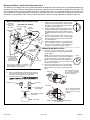
Remove Existing Expansion Valve
1. On fully cased coils, remove the coil access and
plumbing panels.
2. Remove any shipping clamps from the liquid line and
distributor assembly.
3. Disconnect the equalizer line from the check expansion
valve equalizer line tting on the vapor line.
4. Remove the vapor line sensing bulb.
5. Disconnect the liquid line from the check expansion
valve at the liquid line assembly.
6. Disconnect the check expansion valve from the liquid
line orice housing. Take care not to twist or damage
distributor tubes during this process.
7. Remove and discard check expansion valve and the
two Teon® rings (see Figure 3).

506467-01 Page 5 of 19Issue 1946
8. Use a eld-provided tting to temporarily reconnect the
liquid line to the indoor unit’s liquid line orice housing.
SENSING
LINE
TWO-PIECE PATCH PLATE
(UNCASED COIL ONLY)
VAPOR
LINE
DISTRIBUTOR
ASSEMBLY
DISTRIBUTOR
TUBES
LIQUID
LINE
MALE EQUALIZER
LINE FITTING
EQUALIZER
LINE
CHECK
EXPANSION
VALVE
TEFLON
®
RING
STUB END
TEFLON
®
RING
SENSING BULB
LIQUID LINE
ORIFICE
HOUSING
LIQUID LINE
ASSEMBLY WITH
BRASS NUT
Figure 3. Remove Existing Expansion Valve
(uncased coil shown)
Flushing Line Sets
If the unit will be installed in an existing system that uses
an indoor unit or line sets charged with R-22 refrigerant,
installer must perform the following ushing procedure.
NOTE: Existing system components (including line set
and indoor coil) must be an AHRI match with the unit in
order to fulll unit warranty requirements.
Refrigerant must be reclaimed in accordance with
national and local codes.
WARNING
Do NOT attempt to ush and re-use existing line sets
or indoor coil when the system contains contaminants
(i.e., compressor burn out).
CAUTION
“Clean refrigerant” is any refrigerant in a system that
has not had compressor burnout. If the system has
experienced burnout, it is recommended that the
existing line set and indoor coil be replaced.
NOTE
In lieu of R-410A, an industry-standard ushing agent
may also be used.
NOTE
LOW
HIGH
EXISTING
INDOOR
UNIT
GAUGE
MANIFOLD
CYLINDER CONTAINING
CLEAN R-410A TO BE
USED FOR FLUSHING
(Positioned to deliver liquid
refrigerant)
LIQUID LINE SERVICE
VALVE
INLET
DISCHARGE
TANK
RETURN
CLOSED
OPENED
RECOVER
Y
CYLINDER
RECOVERY MACHINE
NEW
OUTDOOR
UNIT
VAPOR LINE
SER
VICE VALVE
VAPOR
LIQUID
1
A
B
C
D
A
Cylinder with clean R-410A (positioned to deliver liquid refrigerant) to the
vapor service valve.
B Refrigerant gauge set (low side) to the liquid line valve.
C
Refrigerant gauge set center port to inlet on the recovery machine with
an empty recovery tank connected to the gauge set.
D Connect recovery tank to recovery machine per machine instructions.
Figure 4.
1. Connect gauges and equipment as shown in Figure 4.
2. Set the recovery machine for liquid recovery and start
the recovery machine. Open the gauge set valves to
allow the recovery machine to pull a vacuum on the
existing system line set and indoor unit coil.
3. Position the cylinder of clean R-410A for delivery of
liquid refrigerant and open its valve to allow liquid
refrigerant to ow into the system through the vapor
line valve. Allow the refrigerant to pass from the
cylinder and through the line set and the indoor unit
coil before it enters the recovery machine.
4. After all of the liquid refrigerant has been recovered,
switch the recovery machine to vapor recovery so
that all of the R-410A vapor is recovered. Allow the
recovery machine to pull the system down to 0.
5. Close the valve on the inverted R-410A drum and the
gauge set valves. Pump the remaining refrigerant out
of the recovery machine and turn the machine o.

Page 6 of 19 506467-01Issue 1946
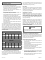
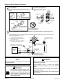
Refrigerant Piping - Install Indoor Expansion Valve
This outdoor unit is designed for use in systems that include an expansion valve metering device (purchased separately) at
the indoor coil. See the Product Specications for approved expansion valve kit match-ups and application information. The
check expansion valve unit can be installed internal or external to the indoor coil. In applications where an uncased coil is
being installed in a eld-provided plenum, install the check/expansion valve in a manner that will provide access for future
eld service of the expansion valve. Refer to below illustration for reference during installation of expansion valve unit.
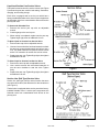
1 - Attach the vapor line sensing bulb in the proper
orientation as illustrated to the right using the clamp and
screws provided.
NOTE - Though it is preferred to have the sensing bulb
installed on a horizontal run of the vapor line, installation
on a vertical run of piping is acceptable if necessary.
NOTE - Confirm proper thermal contact between vapor
line and check/expansion bulb before insulating the
sensing bulb once installed.
2 - Connect the equalizer line from the check expansion
valve to the equalizer vapor port on the vapor line. Finger
tighten the flare nut plus 1/8 turn (7 ft-lbs) as illustrated
below.
TWO PIECE
PATCH PLATE
(UNCASED
COIL ONLY)
VAPOR
LINE
LIQUID LINE
ORIFICE
HOUSING
DISTRIBUTOR
TUBES
LIQUID LINE
MALE EQUALIZER LINE
FITTING (SEE
EQUALIZER LINE
INSTALLATION FOR
FURTHER DETAILS)
SENSING
LINE
EQUALIZER
LINE
CHECK
EXPANSION
VALVE
TEFLON
®
RING
(Uncased Coil Shown)
Sensing bulb insulation is required if
mounted external to the coil casing. sensing
bulb installation for bulb positioning.
STUB
END
TEFLON
®
RING
LIQUID LINE
ASSEMBLY WITH
BRASS NUT
DISTRIBUTOR
ASSEMBLY
3 - Install one of the provided Teflon
®
rings around the
stubbed end of the check expansion valve and lightly
lubricate the connector threads and expose surface of
the Teflon
®
ring with refrigerant oil.
4 - Attach the stubbed end of the check expansion valve to
the liquid line orifice housing. Finger tighten and use an
appropriately sized wrench to turn an additional 1/2 turn
clockwise as illustrated in the figure above, or tighten to
20 ft-lb.
5 - Place the remaining Teflon
®
washer around the other
end of the check expansion valve. Lightly lubricate
connector threads and expose surface of the Teflon
®
ring with refrigerant oil.
6 - Attach the liquid line assembly to the check expansion
valve. Finger tighten and use an appropriately sized
wrench to turn an additional 1/2 turn clockwise as
illustrated in the figure above or tighten to 20 ft-lb.
ON 7/8” AND LARGER LINES,
MOUNT SENSING BULB AT
EITHER THE 4 OR 8 O'CLOCK
POSITION.
12
ON LINES SMALLER THAN
7/8”, MOUNT SENSING
BULB AT EITHER THE 3 OR
9 O'CLOCK POSITION.
12
BULB
VAPOR LINE
VAPOR LINE
NOTE - NEVER MOUNT THE SENSING BULB ON
BOTTOM OF LINE.
BULB
BULB
BULB
VAPOR LINE
FLARE NUT
COPPER FLARE
SEAL BONNET
MALE BRASS EQUALIZER
LINE FITTING
FLARE SEAL CAP
OR
1
2
3
4
5
6
7
8
9
10
11
12
1/2 Turn
SENSING BULB INSTALLATION
EQUALIZER LINE INSTALLATION
1
2
3
4
5
6
7
8
9
10
11
12
1/8 Turn
1 - Remove and discard either the flare seal cap or flare nut
with copper flare seal bonnet from the equalizer line port
on the vapor line as illustrated in the figure below.
2 - Remove the field-provided
sembly.
INDOOR EXPANSION VALVE INSTALLATION

506467-01 Page 7 of 19Issue 1946
Before brazing, ensure the system is fully
recovered of all refrigerant. Application of a
brazing torch to a pressurized system may
result in ignition of the refrigerant and oil
mixture. Check the high and low pressures
before applying heat.
WARNING
Brazing alloys and ux contain materials which are
hazardous to your health.
Avoid breathing vapors or fumes from brazing
operations. Perform operations only in well-ventilated
areas.
Wear gloves and protective goggles or face shield to
protect against burns.
Wash hands with soap and water after handling brazing
alloys and ux.
WARNING
Use a manifold gauge set designed for use on R-410A
refrigerant systems.
NOTE
ATTACH THE MANIFOLD GAUGE SET FOR BRAZING LIQUID AND VAPOR LINE SERVICE VALVES
OUTDOOR
UNIT
LIQUID LINE
VAPOR LINE
LIQUID LINE SERVICE
VALVE
VAPOR LINE
SERVICE
VALVE
ATTACH
GAUGES
INDOOR
UNIT
VAPOR SERVICE PORT MUST BE OPEN
TO ALLOW EXIT POINT FOR NITROGEN
A - Connect gauge set low pressure side to
liquid line service valve (service port).
B - Connect gauge set center port to bottle of
nitrogen with regulator.
C - Remove core from valve in vapor line
service port to allow nitrogen to escape.
NITROGEN
HIGHLOW
USE REGULATOR TO FLOW
NITROGEN AT 1 TO 2 PSIG.
B
A
C
WHEN BRAZING LINE SET TO
SERVICE VALVES, POINT FLAME
AWAY FROM SERVICE VALVE.
Flow regulated nitrogen (at 1 to 2 psig) through the low-side refrigeration gauge set into the liquid line service port valve, and out of the
vapor line service port valve.
CUT AND DEBUR
CAP AND CORE REMOVAL
Cut ends of the refrigerant lines square (free from nicks or dents)
and debur the ends. The pipe must remain round. Do not crimp end
of the line.
Remove service cap and core from
both the vapor and liquid line service
ports.
1
2
LIQUID LINE SERVICE
VALVE
SERVICE
PORT
CORE
SERVICE PORT
CAP
SERVICE
PORT
CORE
SERVICE
PORT CAP
CUT AND DEBUR
LINE SET SIZE MATCHES
SERVICE VALVE CONNECTION
DO NOT CRIMP SERVICE VALV E
CONNECTOR WHEN PIPE IS
SMALLER THAN CONNECTION
3
VAPOR LINE SERVICE
VALVE
COPPER TUBE
STUB
REFRIGERANT LINE
REDUCER
SERVICE VALVE
CONNECTION
LINE SET SIZE IS SMALLER
THAN CONNECTION
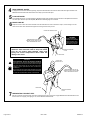
Refrigerant Piping - Brazing Procedures

Page 8 of 19 506467-01Issue 1946
WHEN BRAZING LINE SET TO
SERVICE VALVES, POINT FLAME
AWAY FROM SERVICE VALVE.
LIQUID LINE SERVICE VALVE
LIQUID LINE
BRAZE LINE SET
Wrap both service valves with water-saturated cloths as illustrated here and as mentioned in step 4, before brazing to line set.
Cloths must remain water-saturated throughout the brazing and cool-down process.
WATER-SATURATED
CLOTH
IMPORTANT — Allow braze joint to cool. Apply
additional water-saturated cloths to help cool brazed
joint. Do not remove water-saturated cloths until
piping has cooled. Temperatures above 250ºF will
damage valve seals.
6
VAPOR LINE
WATER-SATURATED
CLOTH
VAPOR LINE
SERVICE VALVE
After all connections have been brazed, disconnect manifold gauge set from service ports. Apply additional water-saturated cloths to both
services valves to cool piping. Once piping is cool, remove all water-saturated cloths.
WHEN BRAZING LINE SET TO
SERVICE VALVES, POINT FLAME
AWAY FROM SERVICE VALVE.
PREPARATION FOR NEXT STEP
7
WRAP SERVICE VALVES
To help protect service valve seals during brazing, wrap water-saturated cloths around service valve bodies and copper tube stubs. Use
additional water-saturated cloths underneath the valve body to protect the base paint.
4
FLOW NITROGEN
Flow regulated nitrogen (at 1 to 2 psig) through the refrigeration gauge set into the valve stem port connection on the liquid service valve and
out of the vapor valve stem port. See steps 3A, 3B and 3C on manifold gauge set connections.
5
WARNING
FIRE, PERSONAL INJURY, OR PROPERTY DAMAGE
may result if you do not wrap a water-saturated cloth around
both liquid and suction line service valve bodies and copper
tube stub while brazing the line set! The braze, when
complete, must be quenched with water to absorb any
residual heat.
Do not open service valves until refrigerant lines and
indoor coil have been leak-tested and evacuated. Refer
to Leak Test and Evacuation section of this manual.
WARNING
While protecting the
service valve seals with
water-saturated cloths,
ensure that water does
NOT enter the system.

506467-01 Page 9 of 19Issue 1946
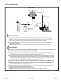
Leak Test and Evacuation
TO VAPOR
SERVICE VALVE
HFC-410A
MANIFOLD GAUGE SET
OUTDOOR UNIT
HIGH
LOW
1
2
A
B
NITROGEN
NOTE - Position
canister to deliver
liquid refrigerant.
A - With both manifold valves closed, connect the cylinder of HFC-410A refrigerant to the center port of the
manifold gauge set. Open the valve on the HFC-410A cylinder (vapor only).
B - Open the high pressure side of the manifold to allow HFC-410A into the line set and indoor unit. Weigh in
a trace amount of HFC-410A. [A trace amount is a maximum of two ounces (57 g) refrigerant or three
pounds (31 kPa) pressure.] Close the valve on the HFC-410A cylinder and the valve on the high
pressure side of the manifold gauge set. Disconnect the HFC-410A cylinder.
C - Connect a cylinder of nitrogen with a pressure regulating valve to the center port of the manifold gauge
set.
D - Adjust nitrogen pressure to 150 psig (1034 kPa). Open the valve on the high side of the manifold gauge set
in order to pressurize the line set and the indoor unit.
E - After a few minutes, open one of the service valve ports and verify that the refrigerant added to the
system earlier is measurable with a leak detector.
F -
After the line set has been connected to the indoor and outdoor units, check the line set connections and
indoor unit for leaks. Use the following procedure to test for leaks:
A - Connect the high pressure hose of an HFC-410A manifold gauge set to the vapor valve service port.
NOTE - Normally, the high pressure hose is connected to the liquid line port. However, connecting it
to the vapor port better protects the manifold gauge set from high pressure damage.
B - With both manifold valves closed, connect the cylinder of HFC-410A refrigerant to the center port of
the manifold gauge set.
CONNECT GAUGE SET
TEST FOR LEAKS
NOTE - Later in the procedure, the HFC-410A container will be replaced by the nitrogen container.
After leak testing, disconnect gauges from service ports.
NOTE - Service valve cores remain removed for the following evacuation procedure.
LEAK TEST

Page 10 of 19 506467-01Issue 1946
A - Open both manifold valves and start the vacuum pump.
B -
NOTE - During the early stages of evacuation, it is desirable to close the manifold gauge valve at least once. A rapid rise in pressure
indicates a relatively large leak. If this occurs, repeat the leak testing procedure.
NOTE - The term absolute pressure means the total actual pressure above absolute zero within a given volume or system. Absolute
pressure in a vacuum is equal to atmospheric pressure minus vacuum pressure.
C - When the absolute pressure reaches 23,000 microns (29.01 inches of
mercury), perform the following:
Close manifold gauge valves.
Close valve on vacuum pump.
Turn off vacuum pump.
Disconnect manifold gauge center port hose from vacuum pump.
Attach manifold center port hose to a nitrogen cylinder with pressure
regulator set to 150 psig (1034 kPa) and purge the hose.
Open manifold gauge valves to break the vacuum in the line set and indoor
unit.
Close manifold gauge valves.
D - Shut off the nitrogen cylinder and remove the manifold gauge hose from the cylinder. Open the manifold gauge valves to release the
nitrogen from the line set and indoor unit.
E - Reconnect the manifold gauge to the vacuum pump, turn the pump on, and continue to evacuate the line set and indoor unit until the
absolute pressure does not rise above 500 microns (29.9 inches of mercury) within a 20-minute period after shutting off the vacuum pump
and closing the manifold gauge valves.
F - When the absolute pressure requirement above has been met, disconnect the manifold hose from the vacuum pump and connect it to a
cylinder of HFC-410A positioned to deliver liquid refrigerant. Open the manifold gauge valve 1 to 2 psig in order to release the vacuum in the
line set and indoor unit.
G - Perform the following:
Close manifold gauge valves.
Shut off HFC-410A cylinder.
Reinstall service valve cores by removing manifold hose from service valve. Quickly install cores with core
tool while maintaining a positive system pressure.
Replace stem caps and finger tighten them, then tighten an additional one-sixth (1/6) of a turn as illustrated.
OUTDOOR
UNIT
TO VAPOR
SERVICE VALVE
TO LIQUID LINE
SERVICE VALVE
MICRON
GAUGE
VACUUM PUMP
1/4 SAE TEE WITH SWIVEL
COUPLER
500
MANIFOLD
GAUGE SET
HFC-410A
RECOMMEND
MINIMUM 3/8” HOSE
A - Connect low side of manifold gauge set with
1/4 SAE in-line tee to vapor line service valve
B - Connect high side of manifold gauge set to
liquid line service valve
C - Connect available micron gauge connector
on the 1/4 SAE in-line tee.
D - Connect the vacuum pump (with vacuum
gauge) to the center port of the manifold
gauge set. The center port line will be used
later for both the HFC-410A and nitrogen
containers.
HIGH
LOW
1
2
3
4
5
6
7
8
9
10
11
12
1/6 TURN
NITROGEN
3
CONNECT GAUGE SET
A
B
C
D
4
EVACUATE THE SYSTEM
NOTE - Remove cores from service valves (if not already done).
Possible equipment damage.
Avoid deep vacuum operation. Do not use
compressors to evacuate a system.
Extremely low vacuum can cause internal
arcing and compressor failure. Damage
caused by deep vacuum operation will
void warranty.
WARNING !
EVACUATION
H - Open suction service valve first before liquid valve to release the unit charge into the system. Replace valve
caps and tighten (8 ft. lb.). Caps are the primary seal.
Evacuate the line set and indoor unit until a slight vacuum is indicated on the micron gauge (approximately 23,000 microns or
29.01 inches of mercury).
NOTE - Position
canister to deliver
liquid refrigerant.

506467-01 Page 11 of 19Issue 1946
Liquid and Suction Line Service Valves
The liquid line and suction line service valves (see Figure
5) and service ports are used for leak testing, evacuation,
charging, and checking charge.
Each valve is equipped with a service port which has a
factory-installed Schrader valve. A service port cap protects
the Schrader valve from contamination and serves as the
primary leak seal.
To Access the Schrader Port:
1. Remove the service port cap with an adjustable
wrench.
2. Connect gauge to the service port.
3. When testing is completed, replace service port cap.
Tighten nger tight, then an additional 1/6 turn.
To Open Liquid or Suction Line Service Valve:
1. Remove stem cap with an adjustable wrench.
2. Use service wrench with a hex-head extension to back
the stem out counterclockwise as far as it will go. Use a
3/16” hex head extension for liquid line service valves
and a 5/16” extension for suction line service valves.
3. Replace the stem cap. Tighten nger tight, then tighten
an additional 1/6 turn.
To Close Liquid or Suction Line Service Valve:
1. Remove the stem cap with an adjustable wrench.
2. Use a service wrench with a hex-head extension to
turn the stem clockwise to seat the valve. Tighten
rmly.
3. Replace the stem cap. Tighten nger tight, then tighten
an additional 1/6 turn.
Suction Line (Ball Type) Service Valve
Suction line (ball type) service valves function the same
way as the other valves; the dierence is in the construction
(see Figure 6).
The ball valve is equipped with a service port with a factory-
installed Schrader valve. A service port cap protects the
Schrader valve from contamination and serves as the
primary seal.
Figure 5.
Figure 6.

Page 12 of 19 506467-01Issue 1946
Electrical Wiring
All eld wiring must be done in accordance with the National
Electrical Code (NEC) recommendations, Canadian
Electrical Code (CEC) and CSA Standards, or local codes,
where applicable.
Electrical Shock Hazard!
Turn OFF electric power before connecting
unit, performing any maintenance or
removing panels or doors. More than one
disconnect may be required to turn o all
power.
FAILURE TO DO SO COULD RESULT IN
BODILY INJURY OR DEATH.
WARNING
Unit must be grounded in accordance with national and
local codes. Failure to ground unit properly can result in
personal injury or death.
WARNING
Line voltage is present at all components when unit is
not in operation on units with single pole contactors.
Disconnect all remote electric power supplies before
opening access panel. Unit may have multiple power
supplies. Failure to disconnect all power supplies could
result in personal injury or death.
WARNING
Refer to the furnace or blower coil Installation Instructions
for additional wiring application diagrams and refer to unit
rating plate for minimum circuit ampacity and maximum
overcurrent protection size.
1. Install line voltage power supply to unit from a properly
sized disconnect switch. Any excess high voltage eld
wiring should be trimmed or secured away from the
low voltage eld wiring.
2. High voltage power connections to 3-phase models
is made to “Pig Tail” leads with eld supplied splice
connectors.
3. Ground unit at unit disconnect switch or to an earth
ground. To facilitate conduit, a hole is in the bottom
of the control box. Connect conduit to the control box
using a proper conduit tting. Units are approved for
use only with copper conductors. 24V Class II circuit
connections are made in the low voltage junction box.
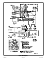
A complete unit wiring diagram is located inside the
unit control box cover.
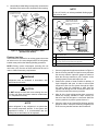
4. Install room thermostat according to thermostat
installation instruction and on an inside wall that is
not subject to drafts, direct sunshine, or other heat
sources.
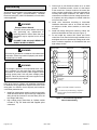
5. Install low voltage wiring from outdoor to indoor unit
and from thermostat to indoor unit (see Figure 7).
6. Do not bundle any excess 24V control wire inside
control box. Run control wire through installed wire tie
and tighten wire tie to provide low voltage strain relief
and to maintain separation of eld-installed low and
high voltage circuits.
1
Refer to thermostat installation instructions
2
“L” is used for any accessories (e.g. diagnostic /
warning / alarm), used to activate thermostat
warning light
R
R
R
C
C
C
G
G
Indoor Blower Only
Y2
Y2
Thermostat Indoor Unit Outdoor Unit
L L
Y1
Compressor /
1st Stage
Y1
1
1
L
Compressor /
2nd Stage
2
W
W1
Heat
1
Figure 7. Thermostat Designations -
Non-Communicating

506467-01 Page 13 of 19Issue 1946
Start-Up
If unit is equipped with a crankcase heater, it should
be energized 24 hours before unit start-up to prevent
compressor damage as a result of slugging.
CAUTION
1. Rotate fan to check for frozen bearings or binding.
2. Inspect all factory and eld-installed wiring for loose
connections.
3. After evacuation is complete, open liquid line and
suction line service valves to release refrigerant
charge (contained in outdoor unit) into system.
4. Replace the stem caps and secure nger tight, then
tighten an additional 1/6 of a turn.
5. Check voltage supply at the disconnect switch. The
voltage must be within the range listed on the unit
nameplate. If not, do not start equipment until the
power company has been consulted and the voltage
condition corrected.
6. Set thermostat for cooling demand, turn on power to
indoor blower, and close the outdoor unit disconnect
switch to start the unit.
7. Recheck unit voltage with unit running. Power must be
within range shown on unit nameplate.
Refrigerant Charging
Excessive amounts of liquid refrigerant entering the
suction line can damage the compressor. When adding
refrigerant, precautions must be taken to control the
ow of liquid into the system. This can be done by using
a liquid vaporizing adapter or manual control using a
sight glass as indicator.
CAUTION
Units are factory charged with the amount of R-410A
refrigerant indicated on the unit rating plate. This charge is
based on a matching indoor coil and outdoor coil with 15’
line set. For varying lengths of line set, refer to Table 4 for
refrigerant charge adjustment. A blank space is provided
on the unit rating plate to list the actual eld charge.
Table 4. Refrigerant Charge Adjustment
Liquid Line Set Diameter
Oz. Per 5 ft. adjust from 15
ft. line set*
3/8 in.
3 oz. per 5 ft.
or 0.6 oz. per 1 ft.
* If line length is greater than 15 ft., add this amount. If line
length is less than 15 ft., remove this amount.
Mineral oils are not compatible with R-410A. If oil must
be added, it must be a polyolester oil.
IMPORTANT
NOTE: Both airow and refrigerant charge must be
monitored for proper system set-up. It may be necessary to
alternately check and adjust the airow and the refrigerant
charge.
If the system is void of refrigerant, or if the outdoor ambient
temperature is cool, use the weigh-in method to charge the
unit. Do this after any leaks have been repaired.
1. Recover the refrigerant from the unit.
2. Conduct a leak check, then evacuate as previously
outlined.
3. Weigh in the charge according to the total amount
shown on the unit nameplate.
If weighing facilities are not available or if unit is being
charged during warm weather, use one of the following
procedures.
• For systems using a xed orice on the indoor
evaporator and outdoor temperatures above
65°F – charge using the superheat method and table
provided on the unit access panel.
• For systems using a TXV on the indoor evaporator
and outdoor temperature above 60°F – charge in
cooling mode using the subcooling method and table
provided on the unit access panel.
• For systems below 60°F – charge in heating mode
using the subcooling method and table provided on
the unit access panel. Attach low pressure gauge
hose to auxiliary service port to access suction side in
heating mode.
NOTE: All unit table values are based on 70 to 80°F
indoor return air temperature for cooling mode, and
65°F to 75°F return air temperature for heat mode.

Page 14 of 19 506467-01Issue 1946
Operation
System Diagnostic Module
4AC16LT units contain a diagnostic module for
troubleshooting air conditioning system failures. By
monitoring and analyzing data from the compressor and
thermostat demand, the module can accurately detect
the cause of electrical and system related failure without
any sensors. If a system problem occurs, a ashing LED
indicator communicates the failure code.
LED Description
POWER LED (Green) indicates voltage is present at the
power connection of the module.
ALERT LET (Yellow) communicates an abnormal system
condition through a unique ash code. The ALERT LED
will ash a number of times consecutively, pause, and then
repeat the process. The number of consecutive ashes
correlates to a particular abnormal condition.
TRIP LED (Red) indicates there is a demand signal
from the thermostat but no current to the compressor is
detected by the module. The TRIP LED typically indicates
the compressor protector is open or may indicate missing
supply power to the compressor.
Interpreting the Diagnostic LEDs
When an abnormal system condition occurs, the
diagnostic module displays the appropriate ALERT and/or
TRIP LED. The yellow ALERT LED will ash a number of
times consecutively, pause, and then repeat the process.
To identify a ash code number, count the number of
consecutive ashes. Refer to Table 5 for information on
the ash codes.
Every time the module powers up, the last ALERT LED
ash code that occurred prior to shutdown is displayed
for 60 seconds. The module will continue to display the
previous ash code until the condition returns to normal
or 24 VAC is removed from the module. TRIP and ALERT
LEDs ashing at the same time means control circuit
voltage is too low for operation.
24 VAC Power Wiring
The diagnostic module requires a constant nominal 24VAC
power supply. The wiring to the module’s R and C terminals
must be directly from the indoor unit or thermostat.
Thermostat Wiring
The diagnostic module requires a thermostat demand
signal to operate properly. See Figure 7 for connections.
The thermostat signal input is 24VAC and should not be
less than 0.5VAC.
Mis-wired Module Codes
Depending on the system conguration, some ALERT ash
codes may not be active. The presence of safety switches
aects how the system alerts are displayed by the module.
Mis-wiring the diagnostic module will cause false LED
codes. Table 6 describes LED operation when the module
is mis-wired and what troubleshooting action is required to
correct the problem.

506467-01 Page 15 of 19Issue 1946
LED Status Fault Description Troubleshooting Information
POWER
(Green)
Module has power Supply voltage is present at module terminals
TRIP
(Red)
Thermostat demand signal
Y1 is present, but the
compressor is not running
1. Compressor protector is open
• Check for high head pressure
• Check compressor supply voltage
2. Outdoor unit power disconnect is open
3. Compressor circuit breaker or fuse(s) is open
4. Broken wire or connector is not making contact
5. Low pressure switch open if present in system
6. Compressor contactor has failed open
ALERT
(Yellow)
Flash Code 1
Long Run Time
Compressor is running
extremely long run cycles
--
ALERT
(Yellow)
Flash Code 2
System Pressure Trip
Discharge or suction
pressure out of limits or
compressor overloaded
1. High head pressure
• Check high pressure switch if present in system
• Check if system is overcharged with refrigerant
• Check for non-con
densable in system
2. Condenser coil poor air circulation (dirty, blocked, damaged)
3. Condenser fan is not running
• Check fan capacitor
• Check fan wiring and connectors
• Check fan motor for failure or blockage
4. Return air duct has substantial leakage
5. If low pressure switch present in system, check Flash Code 1 information
ALERT
(Yellow)
Flash Code 3
Short Cycling
Compressor is running only
briey
1. Thermostat demand signal is intermittent
2. Time delay relay or control board defective
3. If high pressure switch present, go to Flash Code 2 information
4. If low pressure switch present, go to Flash Code 1 information
ALERT
(Yellow)
Flash Code 4
Locked Rotor 1. Run capacitor has failed
2. Low line voltage (contact utility if voltage at disconnect is low)
• Check wiring connections
3. Excessive liquid refrigerant in compressor
4. Compressor bearing are seized
5. Measure compressor oil level
ALERT
(Yellow)
Flash Code 5
Open Circuit 1. Outdoor unit power disconnect is open
2. Compressor circuit breaker or fuse(s) is open
3. Compressor contactor has failed open
• Check compressor contactor wiring and connectors
• Check for compressor contactor failure (burned, pitted, or open)
• Check wiring and connectors between supply and compressor
• Check for low pilot voltage at compressor contactor coil
4. High pressure switch is open and requires manual reset
5. Open circuit in compressor supply wiring or connections
6. Unusually long compressor protector reset time due to extreme ambient temperature
7. Compressor windings are damaged
• Check compressor motor winding resistance
ALERT
(Yellow)
Flash Code 6
Open Start Circuit
Current only in run circuit
1. Run capacitor has failed
2. Open circuit in compressor start wiring or connections
• Check wiring and connectors between supply and the compressor S terminal
3. Compressor start winding is damaged
• Check compressor motor winding resistance
Table 5. Diagnostic Module Codes

Page 16 of 19 506467-01Issue 1946
LED Status Fault Description Troubleshooting Information
ALERT
(Yellow)
Flash Code 7
Open Run Circuit
Current only in start circuit
1. Open circuit in compressor run wiring or connections
• Check wiring and connectors between supply and the compressor R terminal
2. Compressor run winding is damaged
• Check compressor motor winding resistance
ALERT
(Yellow)
Flash Code 8
Welded Contactor
Compressor always runs
1. Compressor contactor has failed closed
2. Thermostat demand signal not connected to module
ALERT
(Yellow)
Flash Code 9
Low Voltage
Control circuit less than
17VAC
1. Control circuit transformer is overloaded
2. Low line voltage (contact utility if voltage at disconnect is low)
• Check wiring conditions
Table 5. Diagnostic Module Codes
Mis-wired Module Indication Recommended Troubleshooting Action
Green LED is not on; module
does not power up
Determine if both R and C module terminals are connected. Verify voltage is present at module’s R
and C terminals. Review 24VAC Power Wiring section for R and C wiring.
Green LED intermittent;
module powers up only when
compressor runs.
Determine if R and Y terminals are wired in reverse. Verify module’s R and C terminals have a
constant source. Review 24VAC Power Wiring section for R and C wiring.
TRIP LED is on, but system
and compressor check OK.
Verify Y terminal is connected to 24VAC at contactor coil. Verify voltage at contactor coils falls below
0.5VAC when o.
TRIP LED and ALERT LED
ashing together.
Verify R and C terminals are supplied with 19-28VAC.
ALERT Flash Code 3
(compressor short cycling)
displayed incorrectly.
Verify Y terminal is connected to 24VAC at contactor coil. Verify voltage at contactor coil falls below
0.5VAC when o.
ALERT Flash Code 5, 6, or 7
(open circuit, open start circuit,
or open run circuit) displayed
incorrectly.
Check that compressor run and start wires are through module’s current sensing holes. Verify Y
terminal is connected to 24VAC at contactor coil. Verify voltage at contactor coil falls below 0.5VAC
when o.
ALERT Flash Code 6 (open
start circuit) displayed for
Code 7 (open run circuit) or
vice versa.
Check that compressor run and start wires are routed through the correct module sensing holes.
ALERT Flash Code 8
(welded contactor) displayed
incorrectly.
Determine if module’s Y terminal is connected. Verify Y terminal is connected to 24VAC at contactor
coil. Verify 24 VAC is present across Y and C when the thermostat demand signal is present. If not,
R and C are reverse wired. Verify voltage at contactor coil falls below 0.5VAC when o. Review
Thermostat Demand Wiring for Y and C wiring.
Table 6. Mis-wired Module Troubleshooting

506467-01 Page 17 of 19Issue 1946
Maintenance
Regular Maintenance Requirements
Your system should be regularly inspected by a qualied
service technician. These regular visits may include
(among other things) checks for:
• Motor operation
• Ductwork air leaks
• Coil & drain pan cleanliness (indoor & outdoor)
• Electrical component operation & wiring check
• Proper refrigerant level & refrigerant leaks
• Proper airow
• Drainage of condensate
• Air lter(s) performance
• Blower wheel alignment, balance & cleaning
• Primary & secondary drain line cleanliness
Air Filter
Inspect air lters at least monthly and replace or clean as
required. Disposable lters should be replaced. Washable
lters may be cleaned by soaking in mild detergent and
rinsing with cold water. Allow lter to dry before reinstalling.
Replace lters with the arrows pointing in the direction of
airow. Dirty lters are the most common cause of poor
heating / cooling performance and compressor failures.
Indoor Coil
If the system has been operated with a clean lter in place,
it should require minimal cleaning. If cleaning is needed,
call your dealer for service.
Condensate Drain
During cooling season check at least monthly for free ow
of drainage and clean if necessary.
Condenser Coils
Grass cuttings, leaves, dirt, dust, lint from clothes dryers,
and foliage from trees can be drawn into coils by movement
of the air. Clogged condenser coils will lower the eciency
of your unit and could cause damage to the condenser.
Periodically, debris should be brushed from the condenser
coils. Use a soft bristle brush with light pressure only. DO
NOT damage or bend condenser coil ns. Damaged or
bent ns may aect unit operation.
SHARP OBJECT HAZARD!
Condenser coils have sharp edges. Wear adequate
body protection on body extremities (e.g. gloves).
FAILURE TO FOLLOW THIS WARNING COULD
RESULT IN BODILY INJURY.
WARNING
Painted Surfaces
For maximum protection of the unit’s nish, a good grade
of automobile wax should be applied every year. In
geographical areas where water has a high concentration
of minerals (calcium, iron, sulfur, etc.), it is recommended
that lawn sprinklers not be allowed to spray the unit. In
such applications, the sprinklers should be directed away
from the unit. Failure to follow this precaution may result
in premature deterioration of the unit nish and metal
components.
In sea coast areas, special maintenance is required due
to the corrosive atmosphere provided by the high salt
concentration in ocean mists and the air. Periodic washing
of all exposed surfaces and coil will add additional life to
your unit. Please consult your installing dealer for proper
procedures in your geographic area.

Page 18 of 19 506467-01Issue 1946
Important System Information
• Your system should never be operated without a clean
air lter properly installed.
• Return air and supply air registers should be free from
restrictions or obstructions to allow full ow of air.
IF YOUR SYSTEM DOES NOT WORK, BEFORE
REQUESTING A SERVICE CALL:
1. Ensure thermostat is set below (cooling) or above
(heating) room temperature and that the system lever
is in the “COOL”, “HEAT” or “AUTO” position.
2. Check indoor and outdoor disconnect switches.
Conrm circuit breakers are ON or that fuses have not
blown. Reset breakers/replace fuses as necessary.
3. Inspect the outdoor unit for clogged condenser coils,
(grass cuttings, leaves, dirt, dust or lint). Ensure that
branches, twigs or other debris are not obstructing the
condenser fan.
IF YOUR SYSTEM STILL DOES NOT OPERATE,
CONTACT YOUR SERVICING DEALER.
Be sure to describe the problem, and have the model and
serial numbers of the equipment available.
If warranty replacement parts are required, the warranty
must be processed through a qualied distribution location.
Homeowner Information
ELECTRICAL SHOCK HAZARD!
Turn OFF electric power to unit before performing any
maintenance or removing panels or doors.
FAILURE TO DO SO COULD RESULT IN BODILY
INJURY OR DEATH.
WARNING
Thermostat Operation
The wall-mounted thermostat controls your air conditioner.
The thermostat is available in various congurations from
dierent manufacturers. The information below is typical for
most thermostats. Ask your dealer for specic information
regarding the model of thermostat installed.
Fan Switch
In AUTO or INT (intermittent) mode, the blower operates
only when the thermostat calls for heating or cooling. This
mode is generally preferred when humidity control is a
priority.
The ON or CONT mode provides continuous indoor
blower operation, regardless of whether the compressor
is operating. This mode is required when constant air
circulation or ltering is desired.
On models without a fan selection switch, the fan will cycle
with the outdoor unit.
Temperature Indicator
The temperature indicator displays the actual room
temperature.

506467-01 Page 19 of 19Issue 1946
Figure 8. Wiring Diagram
-
 1
1
-
 2
2
-
 3
3
-
 4
4
-
 5
5
-
 6
6
-
 7
7
-
 8
8
-
 9
9
-
 10
10
-
 11
11
-
 12
12
-
 13
13
-
 14
14
-
 15
15
-
 16
16
-
 17
17
-
 18
18
-
 19
19


Allied 4AC16LT Installation guide
- Category
- Split-system air conditioners
- Type
- Installation guide
Ask a question and I''ll find the answer in the document
Finding information in a document is now easier with AI
Related papers
Other documents
-
COMFORT-AIRE RSG1448S1R Operating instructions
-
Lennox 16HPX Series Units Installation guide
-
Whirlpool GOLD W4GH6 User manual
-
Fedders C30ABZ1VF Operating instructions
-
-
-
-
Bard QW Series Literature Assembly
-
ROYALTON 4AC16L36P User manual
-
Broan PSH4BG Installation guide