Craftex CX Series CX800 Owner's manual
- Category
- Lathes
- Type
- Owner's manual

CX800
43” X 20” HEAVY DUTY WOOD LATHE
with VARIABLE SPEED
User Manual

2
TABLE OF CONTENTS
General Safety Instructions for Machines............................................................... 3
Specific Safety Instructions..................................................................................... 4
CX800 Features...................................................................................................... 5
Physical Features ................................................................................................... 6
Proper Grounding ................................................................................................... 7
Un-Packing............................................................................................................. 8
Setup ...................................................................................................................... 8
Installing / Removing Headstock Center................................................................. 9
Installing / Removing Tailstock Center.................................................................... 9
Installing / Removing Faceplate..............................................................................10
Control Panel..........................................................................................................11
Test Run.................................................................................................................12
Tailstock..................................................................................................................13
Inboard Tool Rest ...................................................................................................13
Outboard Tool Rest.................................................................................................14
Spindle Speeds.......................................................................................................14
Work-piece Inspection ............................................................................................15
Spindle Turning.......................................................................................................16
Faceplate Turning...................................................................................................16
Outboard Turning....................................................................................................17
Maintenance ...........................................................................................................17
Belt Replacement....................................................................................................18
Troubleshooting......................................................................................................21
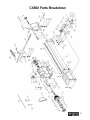
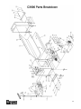
Parts Breakdown................................................................................................22 & 23
Parts List............................................................................................................24 & 25
Warranty.................................................................................................................26

3
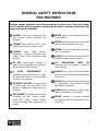
GENERAL SAFETY INSTRUCTIONS
FOR MACHINES
Extreme caution should be used when operating all power tools. Know your power
tool, be familiar with its operation, read through the owner’s manual, and practice safe
usage procedures at all times.
ALWAYS read and understand the
user manual before operating the
machine.
CONNECT your machine ONLY to the
matched and specific power source.
ALWAYS wear safety glasses
respirators, hearing protection and
safety shoes, when operating your
machine.
DO NOT wears loose clothing or
jewelry when operating your machine.
Wear protective hair covering.
A SAFE ENVIRONMENT is
important. Keep the area free of dust,
dirt and other debris in the immediate
vicinity of your machine.
BE ALERT! DO NOT use prescription
or other drugs that may affect your
ability or judgment to safely use your
machine.
DISCONNECT the power source when
changing drill bits, hollow chisels,
router bits, shaper heads, blades,
knives or making other adjustments or
repairs.
NEVER leave a tool unattended while it
is in operation.
NEVER allow unsupervised or untrained
personnel to operate the machine
NEVER reach over the table when the
tool is in operation.
ALWAYS keep blades, knives and bits
sharpened and properly aligned.
ALL OPERATIONS MUST BE
performed with the guards in place to
ensure safety.
ALWAYS use push sticks and feather
boards to safely feed your work through
the machine.
ALWAYS make sure that any tools used
for adjustments are removed before
operating the machine.
ALWAYS keep bystanders safely away
while the machine is in operation.
NEVER attempt to remove jammed
cutoff pieces until the blade has come to
a full stop.

4
Like all power tools and machinery, proper safety and attention must be adhered to.
There is danger associated with using any tool or machine so pay careful attention
each and every time you use your tool. If you are not familiar with the operations of a
lathe, you should obtain the advice and/or instructions from a qualified professional.
Read this operation manual carefully
and understand it before operating the
lathe.
Do not over-reach. Keep proper footing
and balance at all times.
Maintain machine in top condition.
Keep machine clean for best and safest
performance. Follow instructions for
lubrication and changing accessories.
Disconnect the machine from power
source before servicing, changing
accessories, and making any
adjustments.
To avoid accidental starting, make
sure the switch is in the OFF position
before plugging in the power cord.
Never leave the lathe running and
unattended. Turn the power OFF. Do
not leave the machine until it comes to a
complete stop.
Start and stop the machine yourself.
To avoid accidental injuries make sure
not to have anybody help you do this.
Always wear dust mask operation
creates a lot of sawdust and/or chips.
Always operate the tools in a well-
ventilated area and make sure to use a
proper dust collection system for
optimum dust removal.
Turn OFF then machine before making
any adjustments or servicing.
Do not attempt to measure the work-
piece size while the machine is running.
Make sure the work-piece is clamped
securely between the centers before
starting the machine.
Only use correct size centers.
After adjusting or servicing the
machine, remember to remove all
wrenches and other tools from the
machine.
Make sure you have read and
understood the instructions given in
this manual and you are familiar with
your lathe before operating it. If you fail
to do so, serious injury could occur.
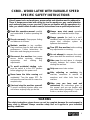
CX800 – WOOD LATHE WITH VARIABLE SPEED
SPECIFIC SAFETY INSTRUCTIONS
WARNING
The safety instructions given above can not be complete because the environment in
every shop is different. Always consider safety first as it applies to your individual
working conditions.

5
MODEL CX800 – HEAVY DUTY WOOD LATHE WITH VARIABLE SPEED
As part of the growing line of Craftex CX-Series woodworking equipment, we are proud to offer
the CX800, a Heavy Duty Wood Lathe with Variable Speed. The Craftex name guarantees
Craft Excellence. By following the instructions and procedures laid out in this user manual, you
will receive years of excellent service and satisfaction. The CX800 is a professional tool and
like all power tools, proper care and safety procedures should be adhered to.
Motor..............................................3-HP, 220-V, 60-Hz, 3-Phase
Amp................................................9-Amp
Number of Speeds..........................Variable Speed, 50 – 3000 RPM
Spindle Taper.................................MT2
Spindle Size....................................1-1/4” x 8 TPI RH
Swing Over Bed..............................20”
Swing Over Tool Rest.....................16-3/4”
Swing Over Gap.............................24-7/8”
Distance Between Centers.............43”
Spindle Speed Ranges...................Variable, 50-100RPM, 100-2000RPM, 150-3000RPM
Tailstock Taper...............................MT2
Bed Construction............................Precision Ground Cast Iron
Stand Construction.........................Pre-Formed Sheet Steel Metal
Headstock Construction..................Cast Iron
Tailstock Construction ....................Cast Iron
Overall Dimensions ........................Length 104” x Width 25” x Height 50”
Approx. Shipping Weight................855 lbs
Warranty.........................................3 Years
CX800 – HEAVY DUTY WOOD LATHE
FEATURES

6
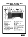
CX800 – HEAVY DUTY WOOD LATHE
PHYSICAL FEATURES

7
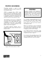
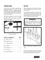
PROPER GROUNDING
Grounding provides a path of least
resistance for electric current to reduce the
risk of electric shock.
CX800 is equipped with a 220-V single
phase motor and is provided with a power
supply cord that is to be connected directly
to the source. Connection must be done by
a qualified electrician in accordance with
electrical code and local electrical codes.
This machine is for use on a normal 220
volt circuit. Make sure that the machine is
connected to an outlet having the same
configuration as the plug. If an adaptor
plug is used, it must be attached to the
metal screw of the receptacle.
To prevent electrical hazards, have a
qualified electrician ensure that the line is
properly wired.
Figure-1 220-Volts outlet for CX800
It is strongly recommended not to use
extension cords with your CX800. Always
try to position your machine close to the
power source so that you do not need to
use extension cords.
When it is necessary to use an extension
cord, make sure the extension cord does
not exceed 50-feet in length and the cord is
12-gauge to prevent motor damage.
Your CX800 should be wired with a plug
having 3-prongs to fit a 3 prong grounded
receptacle as shown in figure-3.
Do not remove the grounding prong to fit it
into a 2-pronged outlet. Always check with
a qualified electrician if you are in doubt.
WARNING
Improper connection of the equipment-
grounding conductor can result in a risk
of electric shock. Check with a qualified
electrician if you are in doubt as to
whether the outlet is properly grounded.

8
UNPACKING
The machine is properly packaged and
shipped complete in a crate for safe
transportation. When unpacking, carefully
inspect the crate to ensure that nothing has
been damaged during transit. Open the
crate and check that the lathe and the parts
are in good condition.
While doing inventory, if you can not find
any part, check if the part is already
installed on the machine. Some of the parts
come pre-assembled.
Figure-2 Inventory
LIST OF CONTENTS QTY
A. Tailstock Center..................................1
B. Headstock Center................................1
C. T-Handle Wrenches ............................2
D. Faceplate ............................................1
E. Knockout Rod......................................1
F. Tool Rests...........................................2
G. Lathe (No Shown) ...............................1
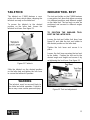
SETUP
Before setting up your machine, you should
read and understand the instructions given
in this manual.
The unpainted surfaces of this lathe are
coated with rust preventive waxy oil and
you will want to remove this before you
begin assembly. Use a solvent cleaner that
will not damage the painted surfaces.
Figure-3 Lifting straps positioned to lift the
lathe
Figure-3 shows where to position the straps
to lift the lathe safely. Make sure when
lifting, the lathe is balance on both sides.
WARNING
CX800 is a very heavy machine. Do not
over-exert yourself. Use a fork truck or
other mechanical devices for safe
moving.

9
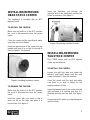
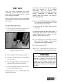
INSTALLING/REMOVING
HEAD STOCK CENTER
The headstock is provided with an MT2
tapered center.
TO INSTALL THE CENTER:
Make sure the switch is in the OFF position
the cord is disconnected from the power
outlet.
Clean the center and the spindle and make
sure they are free of debris.
Insert the tapered end of the center into the
spindle and push it in so that it securely fit
into the spindle. See figure-4.
Figure-4 Installing headstock center
TO REMOVE THE CENTER:
Make sure the switch is in the OFF position
the cord is disconnected from the power
outlet.
Hold the center with one hand so that it
does not fall on the lathe bed when it is
knocked out. See figure-5.
Insert the knockout rod through the
opposite end of the headstock and tap the
center to remove it. See figure-5.
Figure-5 Removing headstock center
INSTALLING/REMOVING
TAILSTOCK CENTER
The CX800 comes with an MT2 tapered
center for the tailstock.
TO INSTALL THE CENTER:
Loosen the quill lock lever and rotate the
tailstock quill hand wheel until the quill
comes out about 1” from the tailstock.
Clean the center and the quill and make
sure there is no dust or debris on the
mating surfaces of both.
Insert the tapered end of the center into the
quill and push it in, making sure that it is
installed securely into the quill. See figure-
6.
Secure the quill in place by re-tightening the
quill lock lever.

10
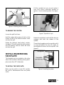
Figure-6 Installing tailstock center
TO REMOVE THE CENTER:
Loosen the quill lock lever.
Hold the center with a piece of cloth so that
it does not fall on the lathe bed when came
out from the quill.
Rotate the tailstock hand wheel counter-
clockwise. This will cause the quill to retract
into the tailstock and the center will come
out from the quill.
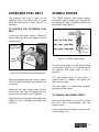
INSTALLING/REMOVING
FACEPLATE
The faceplate can be installed on the other
side of the headstock allowing turning work-
piece more than 20” in diameter.
TO INSTALL THE FACEPLATE:
Make sure the switch is in the OFF position
the cord is disconnected from the power
outlet.
Pull the spindle lock pin out and rotate it
from nine o’clock (unlocked) position to
twelve o’ clock (locked) position. See figure-
7.
Figure-7 Spindle lock pin
Rotate the spindle by hand until the lock pin
engages and locks the rotation of the
spindle.
Thread the faceplate onto the spindle until it
is snug and tighten the four set screws on
the faceplate to secure it to the spindle. See
figure-8.
Figure-8 Installing faceplate

11
TO REMOVE THE FACEPLATE:
Make sure the spindle lock pin is engaged.
Loosen the four screws securing the
faceplate to the spindle and unthread the
faceplate.
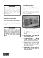
CONTROL PANEL
The control panel for CX800 is located in
front of the machine just below the
headstock.
Refer to figure-9 reading the descriptions
below and familiarize yourself with the
controls on your CX800.
Figure-9 CX800 Control panel
A. ON BUTTON: Starts the spindle
rotation.
B. OFF/EMERGENCY STOP BUTTON:
Stops the spindle rotation.
C. FORWARD/REVERSE SWITCH:
Changes the direction of rotation of the
spindle to clockwise or anticlockwise.
D. SPINDLE SPEED CONTROL KNOB:
Adjusts the spindle speed from low to
high within the range the belt is
positioned on the pulleys.
E. SPINDLE RPM DIGITAL READOUT:
Shows the spindle RPM (rotation per
minute) in digital form.
WARNING
The faceplate must be properly threaded
onto the spindle and secured by
tightening the four set screws to prevent
the work-
p
iece from flying off during
operation. Failure to follow these
instructions could cause serious
personal injuries.
WARNING
Make sure the switch is in the OFF
p
osition and the cord is disconnected
from the power source before installing,
servicing and removing/replacing any
components on the machine. Failure to
do so may result serious personal
injuries.

12
TEST RUN
Once you have assembled your lathe
completely, it is then time for a test run to
make sure that the machine works properly
and is ready for operation.
Remove all the tools used for assembling
the machine and make sure all the guards
are in place.
TO TEST RUN THE CX800:
1. Pull the spindle lock lever out and turn it
to nine o’clock (unlocked) position.
Figure-10 Spindle lock pin
2. Connect the cord to the power outlet.
3. Turn the Spindle Speed Control Knob
and set to zero.
4. Push the ON button in. It should turn the
machine ON and rotate the spindle.
5. Turn the Spindle Speed Control Knob to
increase the spindle speed.
The machine will run smoothly with little
vibration and noise.
If you hear any unusual noise(s) coming
from the machine or if it vibrates
excessively, shut the machine OFF
immediately and disconnect from the power
source. Investigate to determine the
problem with your machine. See page-21
for troubleshooting.
6. Push the OFF/Emergency Stop Button
in, it should turn the machine OFF and
stop the rotation the spindle.
7. Do not re-set the switch and push the
ON button.
The machine should not start at this point. If
the machine gets started, it means that the
safety feature does not work on your
machine and it should be fixed.
8. If the machine runs smoothly, and the
ON and OFF buttons are working
properly proceed to the next step.
9. Turn the machine OFF.
10. Use the Forward/Reverse switch and
turn the spindle in the opposite direction.
WARNING
Do not make any adjustments while the
machine is running. Turn the machine
OFF and un-plug the cord from the
power source before making any
adjustments. Failure to do so may cause
serious personal injury and damage to
the lathe.

13
TAILSTOCK
The tailstock on CX800 features a cam-
action lock lever which allows clamping the
tailstock securely on the lathe bed.
To secure the tailstock to the desired
position on the lathe bed, loosen the
tailstock lock lever. See figure-11.
Figure-11 Tailstock
Slide the tailstock on the desired position
on the lathe bed and tighten the lock lever
to secure the tailstock in position.
INBOARD TOOL REST
The tool rest holder on the CX800 features
a cam-action lock lever that allows securing
it in different positions and different angles
on the lathe bed. The tool rest can also be
positioned and secured in different angles
and height.
TO POSITION THE INBOARD TOOL
REST ON THE LATHE BED:
Loosen the tool rest holder lock lever (see
figure-12) and slide the tool rest holder to
the desired position on the lathe bed.
Tighten the lock lever and secure it in
place.
Loosen the lock lever securing the tool rest
to the holder. Position the tool rest to the
desired angle and height and secure it by
re-tightening the lock lever. See figure-12.
Figure-12 Tool rest adjustment
WARNING
The tailstock must be secured firmly to
the lathe bed while operation. Failure to
do so may cause serious personal injury.

14
OUTBOARD TOOL REST
The outboard tool rest is used on the
outboard side of the lathe and it is used
when the work-piece is more than 20” in
diameter.
TO POSITION THE OUTBOARD TOOL
REST:
Loosen the lock levers shown in figure-13
while holding the tool rest support rod with
another hand.
Figure-13 Outboard tool rest adjustment
Adjust the support brackets shown in figure-
13 to the desired position and retighten the
lock levers.
Adjust the tool rest support rod so that it
rests on the shop floor and tighten the lock
lever to lock the support rod in position.
Adjust the tool rest height and position it as
required for the operation and tighten the
lock lever.
SPINDLE SPEEDS
The CX800 features three speed ranges
and these speed ranges are selected by
positioning the belt on different grooves of
the pulleys. See figure-14.
Figure-14 CX800 speed range
The low speed range is used when turning
a work-piece where a lot of material must
be removed and rough finish is not a
problem.
The high speed range is used when a
smooth finish is required and when only
light cuts are made.
The mid range is a compromise between
the high and low range.
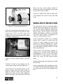
TO CHANGE THE SPINDLE SPEED:
Make sure the switch is in the OFF position
and the cord is disconnected from the
power source.
Loosen the knob securing the belt cover as
shown in figure-15.

15
Figure-15 Removing the belt cover
Open the cabinet door and loosen the lock
lever shown in figure-16 and pull the motor
height lever up to raise the motor and
retighten the lock lever securing the motor
in position. See figure-16.
Figure-16 Motor height handle and lock
lever
Position the belt on the pulleys for the
correct speed range looking at figure-14.
Once the belt is on the right grooves on the
pulleys, loosen the lock lever shown in
figure-16 and the motor will hang freely
against the belt. Let the motor weight to
tension the belt. If the motor does not hang
freely use the motor height handle to
tension the belt the re-tighten the lock lever
to secure the motor in place.
Close the cabinet door and the belt cover
and re-tighten the knob to secure the belt
cover.
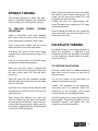
WORK-PIECE INSPECTION
The work-piece must be inspected before
turning. Some work-pieces are not safe to
turn or may require adjustment before they
are safe for turning. Before turning any
wood, make sure to inspect it for nails,
staples, small pieces of stone or metal and
any other object which is dangerous to
come on contact with the chisel.
If the work-piece contains any of these
objects and it comes in contact with the
chisel, the object might fly and hit the
operator or seriously damage the chisel.
For a safe turning operation always inspect
your work-piece carefully before cut and
wear eye protection.
Some woods with excessive twisting or
wrapping are un-stable while cutting and
are dangerous to cut. Do not turn these
work-pieces at a high speed or the work-
piece can come off and cause serious
injury.
Cutting wet or green stock gives poor result
when turned.
Some work-pieces with large/loose knots
can break into half during the operation and
can cause serious injury and damage to the
tool.

16
SPINDLE TURNING
The turning operation in which the work-
piece is mounted between the headstock
and the tailstock is called spindle turning.
TO PERFORM SPINDLE TURNING
OPERATION:
Select a work-piece and draw diagonal
lines from corner to corner across the end
of the work-piece to find the center point.
Take a spur and a mallet and tap center
marks on both ends of the work-piece.
Drill about 1/4" holes on the center marks
on both ends of the work-piece using a 1/4"
drill bit.
You can cut the corners of the work-piece
lengthwise to make turning easier.
Make sure the spur center is aligned with
the mark made on the work-piece and push
the spur center about 1/4" into the work-
piece end.
Insert the spur into the headstock spindle
with the work-piece attached to it and make
sure it is secured.
Install the live center into the tailstock quill
and tighten the quill lock lever to secure the
quill in position.
Now, loosen the tailstock lock lever and
slide the tailstock on the lathe bed towards
the work-piece until the live center comes in
contact with the work-piece. Make sure the
live center is aligned with the marked center
on the end of the work-piece.
Now, loosen the quill lock lever and rotate
the tailstock hand wheel pushing the live
center into the work-piece about 1/4" and
re-tighten the quill lock lever.
Position the tool rest approximately 1/8”
above the work-piece center and 1/4" away
from the work-piece.
Before starting the lathe turn the spindle by
hand, and make sure the work-piece is not
touching the tool rest.
FACEPLATE TURNING
Faceplate turning is the turning operation in
which the work-piece is attached to the
faceplate and then the faceplate is installed
on the headstock spindle (with the work-
piece) for turning.
TO PERFORM FACEPLATING:
Find the center point by drawing diagonal
lines from corner to corner on one end of
the work-piece.
Cut off the corners of the work-piece to
make turning easier and safe.
Position the faceplate on the work-piece
and make sure it is centered. Attach the
work-piece to the faceplate using wood
screws that do no have tapered heads.
Once the work-piece is securely attached to
the faceplate, thread the faceplate onto the
headstock spindle and tighten the four
screws to secure the faceplate.

17
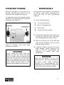
OUTBOARD TURNING
When the work-piece is more than 20” in
diameter, you will need to mount it on the
other side of the headstock for turning.
For outboard turning, the faceplate and the
headstock hand wheel positions should be
exchanged. See figure-17.
Figure-17 Faceplate and hand wheel
positions are swapped
MAINTENANCE
During the life of your machine, you will need
to practice some regular maintenance to
keep your lathe in peak performance
condition.
1. Check the lathe daily for:
A. Loose mounting bolts
B. Worn or damaged wires
C. Worn switch
D. Any other unsafe condition
2. Protect the unpainted cast iron surfaces of
the lathe by clean the chips after every
use and wiping with dry piece of cloth.
3. Apply a thin layer of oil on the bed slide
ways and the unpainted cast iron surface
to keep the bed rust-free.
4. A build up of dust in the motor can cause
motor damage. Periodic cleaning of the
motor is not only recommended, but
mandatory for normal wood lathe
performance.
WARNING
Before starting the lathe rotate the
spindle by hand and make sure that
there is enough clearance between the
work-
p
iece and the tool rest and other
parts on the outboard side of the lathe.
Failure to follow these instructions could
cause serious personal injury to the
operator and damage to the work-piece.
WARNING
Make sure the switch is in the OFF
p
osition and the cord is disconnected from
the power source before installing,
servicing and removing/replacing any
components on the machine. Failure to do
so may result serious personal injuries.

18
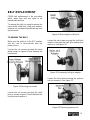
BELT REPLACEMENT
CX800 belt replacement is the procedure
which takes time and you need to be
patient while doing it.
To remove the belt, you need to remove the
hand wheel, shaft joint, shaft joint adaptor,
spanner nut, out-board spindle bearing, and
speed sensor.
TO REMOVE THE BELT:
Make sure the switch is in the OFF position
and the cord is disconnected from the
power source.
Loosen the set screws securing the hand
wheel shown in figure-18 and remove the
hand wheel.
Figure-18 Securing set screws
Loosen the set screws securing the shaft
joint as shown in figure-19 and unthread the
shaft joint and remove it.
Figure-19 Removing the shaft joint
Loosen the set screws securing the shaft joint
adaptor. Unthread the shaft joint adaptor and
remove it. See figure-20.
Figure-20 Removing shaft joint adaptor
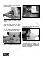
Loosen the set screws securing the spanner
nut and remove it. See figure-21.
Figure-21 Removing spanner nut

19
Remove the outboard spindle bearing as
shown in figure-22.
Figure-22 Removing the outboard spindle
bearing
Loosen the screws securing the speed
sensor, shown in figure-23 and bring the
sensor out and rest it on the headstock
opening.
Now, pull out the spindle lock pin and turn it
to 9 o’ clock position to unlock the spindle.
Figure-23 Uninstalling spindle speed sensor
Open the cabinet door and loosen the
motor lock lever. Use the motor height hand
wheel to raise the motor up. Retighten the
lock lever and remove the belt from the
motor pulley. See figure-24.
Figure-24 Removing the belt from motor
pulley
Remove the belt from the spindle pulley.
Now with one hand holding the spindle from
inside of the headstock, tap the spindle
using mallet from outboard side towards the
tailstock. See figure-25.
Figure-25 Removing the belt
Remove the belt as shown in figure-25 and
clean the outboard and inboard spindle
bearings. Apply a thick layer of grease on
the rollers of the bearings.

20
TO INSTALL THE NEW BELT:
Make sure the switch is in the OFF position
and the cord is disconnected from the
power source.
Install the new belt on the pulleys and insert
the spindle through the outboard end into
the headstock.
Slide the bearing on to the spindle.
Thread the spanner nut onto the spindle.
Hold the faceplate with one hand and
tighten the spanner nut with the other hand
using the hex wrench provided. Secure the
spanner nut by tightening the set screws.
Reinstall the speed sensor on the
headstock and secure it using two screws.
Make sure the speed sensor is not touching
the pulley or the cord is not hanging around
the pulley.
Thread the shaft joint adaptor onto the
spindle and secure it by tightening the set
screws on it.
Align the key way with the key on the shaft
joint and reinstall the shaft joint onto the
shaft joint adaptor securing it by tightening
the set screws.
Install the hand wheel and secure it by
tightening the set screws.
Make sure the belt is installed on the right
grooves on the pulleys and tensioned
properly. Tighten the lock lever to lock the
motor in position and close the cabinet
door.
WARNING
Once the spanner nut is threaded onto
the spindle, rotate the spindle and make
sure the spanner nut is not over-
tightened. Over-tightening the spanner
nut will effect the rotation of the spindle.
WARNING
Make sure the switch is in the OFF
p
osition and the cord is disconnected
from the power source before installing,
servicing and removing/replacing any
components on the machine. Failure to
do so may result serious personal
injuries.
Page is loading ...
Page is loading ...
Page is loading ...
Page is loading ...
Page is loading ...
Page is loading ...
-
 1
1
-
 2
2
-
 3
3
-
 4
4
-
 5
5
-
 6
6
-
 7
7
-
 8
8
-
 9
9
-
 10
10
-
 11
11
-
 12
12
-
 13
13
-
 14
14
-
 15
15
-
 16
16
-
 17
17
-
 18
18
-
 19
19
-
 20
20
-
 21
21
-
 22
22
-
 23
23
-
 24
24
-
 25
25
-
 26
26


Craftex CX Series CX800 Owner's manual
- Category
- Lathes
- Type
- Owner's manual
Ask a question and I''ll find the answer in the document
Finding information in a document is now easier with AI
Related papers
-
Craftex CX Series CX802 Owner's manual
-
-
-
-
-
-
-
-
-
Other documents
-
 Craftex CT172 Owner's manual
-
Rikon Power Tools 70-220VSR User manual
-
 MicroLux 86892 User manual
-
-
 Craftex CT024N Owner's manual
-
 Craftex CT160 User manual
-
Grizzly G0838 Owner's manual
-
Grizzly G0694 User manual
-
-
 Grizzly Industrial G0838 User manual


