
1
Star
Manufacturing
International Inc.
10 Sunnen Drive
St. Louis, MO 63143
Phone: (314) 781-2777
Fax: (314) 781-3636
Installation
and
Operating
Instructions
ULTRA-MAX GAS HOTPLATE
MODELS
8I-802H-LP 8I-804H-LP
8I-806H-LP 8I-808H-LP
2M-Z7923 Rev. -- 6/1/04
WARNING: Improper installation,
adjustment, alteration, service or
maintenance can cause property damage,
injury or death. Read the installation,
operating and maintenance instructions
thoroughly before installing or servicing this
equipment.
FOR YOUR SAFETY: Do not store or use
gasoline or other flammable vapors or liquids
in the vicinity of this or any other appliance.
WARNING: This appliance shall be installed
in accordance with current regulations and
used only in well-ventilated space. Refer to
instructions before installing and using this
appliance.
In addition, there should be posted, in a
prominent location, detailed instructions to
be followed in the event the operator smells
gas. Obtain the instructions from the local
gas supplier.

2
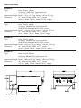
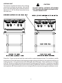
SPECIFICATIONS
8I-802H-LP
Type: Manual Control, 2-Burner
2 Controls, 52,000 BTUH Total Propane Gas
(30,000 BTUH Nat/26,000 BTUH LP per burner)
Approximate Weight: Installed - 70 Lb s (31.7 kg), shipping - 120 Lbs (54.4 kg)
Dimensions: 12" - Width, 30 5/8" - Depth, 14 7/8" - Height
(30.5 cm - Width, 77.8 cm - Depth, 37.8 cm - Height)
8I-804H-LP
Type: Manual Control, 4-Burner
4 Controls, 104,000 BTUH Total Propane Gas
(30,000 BTUH Nat/26,000 BTUH LP per burner)
Approximate Weight: Installed - 140 Lbs (63.5 kg), shipping - 216 Lbs, (97.9 kg)
Dimensions: 24" - Width, 30 5/8" - Depth, 14 7/8" - Height
(61 cm - Width, 77.8 cm - Depth, 37.8 cm - Height)
8I-806H-LP
Type: Manual Control, 6-Burner
6 Controls, 156,000 BTUH Total Propane Gas
(30,000 BTUH Nat/26,000 BTUH LP per burner)
Approximate Weight: Installed - 210 Lbs (95.2 kg), shipping - 294 Lbs, (133.3 kg)
Dimensions: 36" - Width, 30 5/8" - Depth, 14 7/8" - Height
(91.4 cm - Width, 77.8 cm - Depth, 37.8 cm - Height)
8I-808H-LP
Type: Manual Control, 8-Burner
8 Controls, 208,000 BTUH Total Propane Gas
(30,000 BTUH Nat/26,000 BTUH LP per burner)
Approximate Weight: Installed - 280 Lbs (127 kg), shipping - 380 Lbs, (172.3 kg)
Dimensions: 48" - Width, 30 5/8" - Depth, 14 7/8" - Height
(122 cm - Width, 77.8 cm - Depth, 37.8 cm - Height)

3
This symbol is intended to alert the user to the presence of important
operating and maintenance instructions in the manual accompanying
the appliance.
RETAIN THIS MANUAL FOR FUTURE REFERENCE
NOTICE
Using any part other than genuine Star factory supplied parts relieves
the manufacturer of all liability.
NOTICE
Star reserves the right to change specifications and product design
without notice. Such revisions do not entitle the buyer to corre-
sponding changes, improvements, additions or replacements for
previously purchased equipment.
MAINTENANCE AND REPAIRS
Contact your local authorized service agent for service or required maintenance. Refer to the authorized service
center listing provided with the unit. The Star Service Help Desk (1-800-807-9054) is available during normal
business hours to answer any questions that may arise. Please have your model number and serial number for faster
service.
SAFETY SYMBOL

4
GENERAL INSTALLATION DATA
CAUTION
This equipment is designed and sold for commercial
use only by personnel trained and experienced in its
operation and is not sold for consumer use in and
around the home nor for use directly by the general
public in food service locations.
The Ultra-Max™ series gas hotplate is equipped for
the type of gas indicated on the nameplate mounted
on the front panel. All units are shipped from the
factory for use with propane gas. The unit can easily be
converted for use with natural gas: see Natural Gas -
Conversion.
-IMPORTANT-
Be sure to remove all paper protection and packing
material from unit prior to lighting.
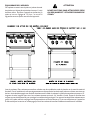
Install on non-combustible countertop with 4"
legs or combustible floor using a maximum 27"
high stand. Clearance from combustible
construction must be 9" minimum from back
wall and 7" from side walls. Clearance from non-
combustible surfaces on back and sides may be
0". For servicing, 6" is recommended from back
of unit on non-combustible walls.
The installation of the Appliance must conform
to the NATIONAL FUEL GAS CODE "ANSI
Z223.1 - LATEST EDITION" AND ALL LOCAL
GAS COMPANY RULES AND
REGULATIONS.
IN CANADA INSTALLATION SHALL BE IN
ACCORDANCE WITH THE CURRENT
CAN/CGA-B149.1 NATURAL GAS
INSTALLATION CODE OR CAN/CGA-
B149.2 PROPANE INSTALLATION CODE
AND LOCAL CODES WHERE APPLICABLE.
NOTICE
When this appliance is installed with casters, it must be
installed with the casters supplied, a connector
complying with either ANSI Z21.69 or CAN/CGA-
6.16 and a quick-disconnect device complying with
either ANSI Z21.41 or CAN1-6.9. It must also be
installed with restraining means to guard against
transmission of strain to the connector, as specified in
the appliance manufacturer's instructions.
For your protection, we recommend a qualified
installing agency install this appliance. They should
be familiar with gas installations and your local
gas requirements. In any case, your gas company
should be called to approve the final installation.
This appliance, its pressure regulator and its individual
shutoff valve must be disconnected from the gas
supply piping system during any pressure testing of that
system at test pressures in excess of 1/2 PSIG. This
appliance and its pressure regulator must be isolated
from the gas supply piping system by closing its individual
manual shutoff valve during any pressure testing of the
gas supply piping system at test pressures equal to or
less than 1/2 PSIG.
EXHAUST CANOPY
Open hotplates create fumes, moisture, heat, and
should be installed under an efficient exhaust hood
with flame proof filters. A vertical distance of not less
than 48" shall be provided between the top of the
appliance and filters or any other combustible material.
Exhaust installation must conform to local codes.
AIR SUPPLY
Provisions for adequate air supply must be provided.
CAUTION
AIR INTAKES IN BOTTOM
Air for combustion enters from the front and bottom
of the unit. Do not obstruct this area.

5
LEVELING UNIT
This hotplate is supplied with 4 feet or floor stand legs
which must be screwed into the body. Unit must be
level. Level unit by adjusting the (4) feet which have an
adjustment of 1-3/4" for accurate and perfect line-up
with other units.
Caster Kits: Casters can be used with floor stand models or optional equipment stand. For installation, carefully
mark and cut off from the bottom of each leg using a straight cutting saw and de-burr the inside tube wall prior to
installing the caster. Cut leg should measure 19" tube length, not overall length. Casters add about 6-1/4" of height
to the unit. Be sure to use approved strain relief means for protecting gas line connection. If an appliance is equipped
with casters and is gas connected with a quick connect coupling, all personnel must be aware that there is a restraint
on the appliance and if disconnected for service or cleaning it must be reconnected as originally installed prior to use.
CAUTION
DO NOT INSTALL WITHOUT ATTACHING
FEET OR SUPPLIED STAND LEGS AND SHELF
- DO NOT REMOVE FEET.

6
GAS PIPING
Gas piping shall be of such size and so installed as to
provide a supply of gas sufficient to meet the full gas
input of the appliance. If the appliance is to be connected
to existing piping, it shall be checked to determine if it
has adequate capacity. Joint compound shall be used
sparingly and only on the male threads of the pipe
joints. Such compounds shall be resistant to the action
of L.P. gases.
WARNING: Any loose dirt or metal particles which
are allowed to enter the gas lines on this appliance will
damage the valve and affect its operation. When
installing this appliance, all pipe and fittings must be free
from all internal loose dirt.
GAS PRESSURE REGULATOR
A convertible pressure regulator is provided with each
hotplate. It should be connected to the inlet pipe at the
rear of the unit. The gas supply is then connected to it.
The supply pressure to the regulator is not to exceed
1/2 PSIG. It is shipped set for 10" water column
manifold pressure for use with propane gas.
MANUAL SHUT OFF VALVE
A manual shut off valve should be installed upstream
from the manifold and within six feet of the hotplate.
CONNECTING GAS SUPPLY LINE
The gas inlet of the hotplate is sealed at the factory to
prevent entry of dirt. Do not remove this seal until the
actual connection is made to the gas supply line.
NATURAL GAS - CONVERSION
This hotplate is equipped with fixed orifice hoods and
is shipped from the factory for use with propane gas.
To convert to natural gas, install the burner orifice
hoods, located on the manifold, as follows:
1. Remove grates and burners.
2. Remove the burner orifice hoods and install the
orifice hoods supplied.
3. Replace the burners and grates. Be sure the
venturi opening is positioned on valve orifice.
4. Set manifold pressure to (5) inch water column. A
1/8" pipe plug on the burner manifold can be
removed for attaching a pressure gauge. Remove
the slotted, or hex-threaded plug from the pressure
regulator. Invert the plug and re-install. The
letters "NAT" should now be visible on the plug.
The regulator is now set for 5" (12.7 cm) water
column. The pilot flame may need to be adjusted
for NAT gas.
CHECKING FOR GAS LEAKS
Check entire piping system for leaks. Soap and water
solution or other material acceptable for the purpose,
shall be used in locating gas leakage.
CAUTION
Matches, candle flame or other sources of ignition
shall not be used for locating gas leaks.
PILOT LIGHTING INSTRUCTIONS
The hotplate is equipped with factory pre-set
standing pilots and should be lit immediately
after the gas is turned on.
Pilot lights may need an adjustment based on local gas
supplies. See below for pilot light adjustments. If the
operator smells gas or the pilot lights need to be relit:
1. Turn off main valve to unit.
2. Turn off all knobs and pilot valves and wait 5
minutes to clear gas.
3. The pilot lights on this hotplate can be adjusted by
turning the adjustable screw counterclockwise to
open and clockwise to close.
4. Turn on main valve and light all pilots.
5. Adjust pilot light flames as small as possible around
pilot head, usually about 1/4" high, but high enough
to light burner immediately when burner valve is
turned on high.
6. Turn burner knobs to desired setting.
7. To turn burners off, turn knobs clockwise to
"OFF."

7
COMPLETE SHUTDOWN INSTRUCTIONS
Turn the burner valve knobs to the OFF position to
turn burners off and close manual valve gas shutoff.
CLEANING
Clean regularly. Be sure appliance has cooled down.
Remove grate section and burner head to sink for
washing. Brush out carboned particles. Venturi must
be free from grease, dirt, lint, or any foreign material.
Remove and wash crumb pan. Be sure to replace
top grates laying flat and centered over the burner.
Wipe exterior surfaces with a mild detergent and a
cloth. A non-abrasive cleaner can be used on caked
areas. Be careful with spraying on some cleaners as
they may contain abrasives and caustics which could
scratch or damage the finish.
BURNER IGNITION AND ADJUSTMENT
1. To ignite burners turn burner valve knob counter
clockwise to "ON"position.
2. Slowly decrease openings of air shutters to give a
soft blue flame having luminous tips, then slowly
increase openings to a point where the yellow tips
disappear and a hard blue flame is obtained.
LIGHTING
When hotplate is first lit, it may smoke for
approximately 20-30 minutes until the preservation
oils and impurities are burned off.
OPERATING INSTRUCTIONS
BOTTOM CRUMB PAN
The crumb pan is located at the bottom of the unit, and
is easily removed from the front of the unit for
cleaning. Be sure it is in place during operation.
BURNER OPERATION
Each burner is controlled by an individual on-off valve.
A variety of temperatures may be obtained by turning
the burner valve knob to any position between ON
and OFF. It is possible through this arrangement to
have a high heat section, while having a low heat
simmering or holding section. For the high heat
operation, turn the valve counter clockwise for the
section to a position of ON or close to it. For holding
or simmering, turn the valves closer to the OFF
position on the dial. If even less heat is required, the
valve may be turned OFF and the product kept warm
on the pilot flame. You select the heat pattern you like
and set the valves accordingly. Be sure burners are
staying fully lit when set in low positions.
RETAIN THIS MANUAL FOR FUTURE REFERENCE
Part No. 2M-Z7923 Rev. -- 6/1/04

8
Part# 2M-4497-2 11/03 RB
The foregoing warranty is in lieu of any and all other warranties expressed or implied and constitutes the entire warranty.
FOR ASSISTANCE
Should you need any assistance regarding the operation or maintenance of any Star equipment write, phone, fax, or e-mail our Service Department.
In all correspondence mention the model number and the serial number of your unit and the voltage or type of gas you are using.
ALL:
* Pop-Up Toasters
* Butter Dispensers
* Pretzel Merchandisers
* Pastry Display Cabinets
* Nacho Chip Merchandisers
* Accessories of any kind
* Sneeze Guards
* Pizza Ovens
* Heat Lamps
* Hot Cups
* Pumps
Visit our Website at: www.star-mfg.com E-mail: [email protected] For Fax-On-Demand Literature: (800) 807-9814
THOROUGHLY INSPECT YOUR UNIT ON ARRIVAL
This unit has been tested for proper operation before leaving our plant to insure delivery of your unit in perfect condition. However, there are instances in which the
unit may be damaged in transit. In the event you discover any type of damage to your product upon receipt, you must immediately contact the transportation company
who delivered the item to you and initiate your claim with same. If this procedure is not followed, it may affect the warranty status of the unit.
LIMITED EQUIPMENT WARRANTY
All workmanship and material in Star products have a one (1) year limited warranty on parts and labor in the United States and Canada. Such warranty is limited to
the original purchaser only and shall be effective from the date the equipment is placed in service. Star's obligation under this warranty is limited to the repair of defects
without charge, by the factory authorized service agency or one of its sub-agencies. Models that are considered portable (see below) should be taken to the closest
Star service agency, transportation prepaid.
> Star will not assume any responsibility for loss of revenue.
> On all shipments outside the United States and Canada, see International Warranty.
* The warranty period for the JetStar series six (6) ounce popcorn machines is two (2) years.
* The warranty period for the Chrome-Max Griddles is five (5) years on the griddle surface. See detailed warranty provided with unit.
* The warranty period for Teflon/Dura-Tec coatings is one year under normal use and reasonable care. This warranty does not apply if damage occurs to Teflon/
Dura-Tec coatings from improper cleaning, maintenance, use of metallic utensils, or abrasive cleaners. This warranty does not apply to the "non-stick” properties
of such materials.
>This warranty does not apply to "Special Products" but to regular catalog items only. Star's warranty on "Special Products" is six (6) months on parts and ninety (90)
days on labor.
>This warranty does not apply to any item that is disassembled or tampered with for any purpose other than repair by a Star Authorized Service Center or the Service
Center's sub-agency.
>This warranty does not apply if damage occurs from improper installation, misuse, wrong voltage, wrong gas or operated contrary to the installation and operating
instructions.
> This warranty is not valid on Conveyor Ovens unless a "start-up/check-out" has been performed by a Factory Authorized Technician.
PARTS WARRANTY
Parts that are sold to repair out of warranty equipment are warranted for ninety (90) days. The part only is warranted. Labor to replace the part is chargeable to
the customer.
SERVICES NOT COVERED BY WARRANTY
PORTABLE EQUIPMENT
Star will not honor service bills that include travel time and mileage charges for servicing any products considered "Portable" including items listed below. These
products should be taken to the Service Agency for repair:
1. Travel time and mileage rendered beyond the 50 mile radius limit
2. Mileage and travel time on portable equipment (see below)
3. Labor to replace such items that can be replaced easily during a daily cleaning
routine, ie; removable kettles on fryers, knobs, grease drawers on griddles, etc.
4. Installation of equipment
5. Damages due to improper installation
6. Damages from abuse or misuse
7. Operated contrary to the Operating and Installation Instructions
8. Cleaning of equipment
9. Seasoning of griddle plates
10. Voltage conversions
11. Gas conversions
12. Pilot light adjustment
13. Miscellaneous adjustments
14. Thermostat calibration and by-pass adjustment
15. Resetting of circuit breakers or safety controls
16. Replacement of bulbs
17. Replacement of fuses
18. Repair of damage created during transit, delivery, &
installation OR created by acts of God
* The Model 510F Fryer
* The Model 526TO Toaster Oven
* The Model J4R, 4 oz. Popcorn Machine
* The Model CFS Series Food Steamer
* The Model 526WO Warming Oven
* The Model 518CM & 526CM Cheese Melter
* The Model 12MC & 15MC & 18MCP Hot Food Merchandisers
* The Model 12NCPW & 15NCPW Nacho Chip/Popcorn Warmer
* All Hot Dog Equipment except Roller Grills & Drawer Bun Warmers
* All Nacho Cheese Warmers except Model 11WLA Series Nacho Cheese Warmer
* All Condiment Dispensers except the Model CSD, HPD, & SPD Series Dispenser
* All Specialty Food Warmers except Model 130R, 500, 11RW Series, and 11WSA Series
Page is loading ...

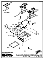
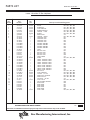
10
PARTS LIST EFFECTIVE
IMPORTANT: WHEN ORDERING, SPECIFY VOLTAGE OR TYPE GAS DESIRED PAGE
INCLUDE MODEL AND SERIAL NUMBER OF
Some items are included for illustrative purposes only and in certain instances may not be available.
Number
Per
Unit
Description and Model Designation
Star Manufacturing International, Inc.
MODEL
Part
Number
Key
Number
6/1/04 Rev. --
1 2F-Z0637 2/4/6/8 GRATE 802 / 804 / 806 / 808
2 2F-Z5473 2/4/6/8 BURNER SET 802 / 804 / 806 / 808
3 I5-Z5463 2/4/6/8 PILOT BRACKET 802 / 804 / 806 / 808
4 I5-Z5464 1/2/3/4 BURNER BRACKET 802 / 804 / 806 / 808
5 2F-Z5475 1/2/3/4 VENTURI - LONG 802 / 804 / 806 / 808
6 2I-Z5476 2/4/6/8 GASKET 802 / 804 / 806 / 808
7 2J-Z4686 1 REGULATOR ALL
8 2F-Z5474 1/2/3/4 VENTURI - SHORT 802 / 804 / 806 / 808
9 2K-Z5459 1 MANIFOLD PIPE 802
2K-Z5460 1 MANIFOLD PIPE 804
2K-Z5461 1 MANIFOLD PIPE 806
2K-Z5462 1 MANIFOLD PIPE 808
10 I5-HP0000 1 WELDED ASSEMBLY 802
I5-HP0001 1 WELDED ASSEMBLY 804
I5-HP0002 1 WELDED ASSEMBLY 806
I5-HP0003 1 WELDED ASSEMBLY 808
11 2A-Z4614 4 FOOT ALL
12 I5-Z5469 1 BOTTOM PAN 802
I5-Z5470 1 BOTTOM PAN 804
I5-Z5471 1 BOTTOM PAN 806
I5-Z5470 2 BOTTOM PAN 808
13 2M-Y7134 1 STAR EMBLEM ALL
14 2R-Z4997 2/4/6/8 KNOB 802 / 804 / 806 / 808
15 2M-Z5478 1 FRONT CONTROL LABEL 802
2M-Z5479 1 FRONT CONTROL LABEL 804
2M-Z5480 1 FRONT CONTROL LABEL 806
2M-Z5481 1 FRONT CONTROL LABEL 808
16 I5-HP0008 1 FRONT PANEL ASSEMBLY 802
I5-HP0009 1 FRONT PANEL ASSEMBLY 804
I5-HP0010 1 FRONT PANEL ASSEMBLY 806
I5-HP0011 1 FRONT PANEL ASSEMBLY 808
17 2V-Y8832 2/4/6/8 GAS VALVE 802 / 804 / 806 / 808
18 I5-HP0014 2/4/6/8 PILOT ASSEMBLY 802 / 804 / 806 / 808
19 2K-Z5458 1/2/3/4 FITTING - 1/4" TEE 802 / 804 / 806 / 808
20 2A-Z5538 2/4/6/8 ORIFICE #42 NATURAL 802 / 804 / 806 / 808
2J-Y7136 2/4/6/8 ORIFICE #53 LP 802 / 804 / 806 / 808
21 2P-1453 1 PIPE PLUG - 1/8" NPT ALL
22 2V-6671 1/2/3/4 PILOT VALVE 802 / 804 / 806 / 808
23 I5-Z5472 1 PAN SUPPORT BRACKET 808
24 I5-Z5532 2 DEFLECTOR 808
25 I5-Z5465 1 REAR PANEL 802
I5-Z5466 1 REAR PANEL 804
I5-Z5467 1 REAR PANEL 806
I5-Z5468 1 REAR PANEL 808
26 2K-Z4920 1/2/3/4 PILOT TUBE 802 / 804 / 806 / 808
1
1
8I-802H-LP, 804H-LP, 806H-LP, 808H-LP
Ultra-Max LP Gas Hotplates
Page is loading ...
Page is loading ...
Page is loading ...
Page is loading ...
Page is loading ...
Page is loading ...
-
 1
1
-
 2
2
-
 3
3
-
 4
4
-
 5
5
-
 6
6
-
 7
7
-
 8
8
-
 9
9
-
 10
10
-
 11
11
-
 12
12
-
 13
13
-
 14
14
-
 15
15
-
 16
16


Star Manufacturing 8I-808H-LP Operating instructions
- Type
- Operating instructions
- This manual is also suitable for
Ask a question and I''ll find the answer in the document
Finding information in a document is now easier with AI
in other languages
Related papers
-
Star Manufacturing 8I-808H-LP Operating instructions
-
-
-
-
Star Manufacturing CSD-2-H Operating instructions
-
Star Manufacturing 8024CB Operating instructions
-
-
Star Manufacturing 8160RCBA Installation And Operating Instructions Manual
-
-
Star Manufacturing ULTRA-MAX 836TSCHS Operating instructions
Other documents
-
Star 806HA Owner's manual
-
 Star Max 624MF Installation And Operation Instructions Manual
-
Wells Manufacturing G-15 User manual
-
-
Star TMHP4 Owner's manual
-
Star 604HF-SU Owner's manual
-
Wells Manufacturing H-2412G Operating instructions
-
Nieco Corporation 1020 Operating instructions
-
Wells H-2412G User manual
-
