
Technical Assistance
• TopWorx engineers are available to provide technical
assistance on GO
™
Switch products. However, it is the cus-
tomer's responsibility to determine the safety and suitability of
the product in their application. It is also the customer's re-
sponsibility to install the switch using the current electrical
codes in their region.
Special Conditions for Safe Use
• The 70 Series GO Switch with Connection Head assembly
shall be suitably earthed by its installation via the male thread
of the GO Switch body.
• Do not allow dust layers to build up on this product.
• All terminal screws, used and unused, shall be fully tight-
ened down by end user.
• No more than one single multi-stranded lead shall be
connected to the terminal unless multiple conductors have
been joined in a suitable manner, e.g. two conductors into a
single insulated bootlace ferrule, or any method indicated on
the terminal certificate.
• All terminals and accessories, such as cross-connectors,
shall be installed in accordance with the terminal manufactur-
er’s instructions. TopWorx Incorporated will supply the rele-
vant terminal manufacturer’s instructions with each assembly
covered by Baseefa09ATEX0281X & IECEx BAS 09.0135X
certificates.
• The maximum voltage and current shown in the rating label
must not be exceeded.
• When connecting conductors of cross section below the
maximum 2.3mm³ allowed for the terminal, then the maximum
amps per pole must be reduced inline with the maximum amps
permitted for a terminal equivalent to the conductor size fitted.
IOM
Air and Hydraulic Cylinders
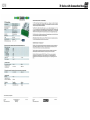
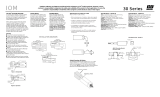
A ferrous cylinder cushion or piston will actuate the switch. To
determine the correct thread length, measure the distance from
the head cap surface to the cushion and add 1/2" for seal nut.
Thread seal nut onto switch. Screw switch into cylinder by hand
until switch touches cushion. Back out 1/4 to 1/2 turn. Tighten seal
nut.
Cylinder Applications Switch Sealing Torque Values
Models 73, 75 & 7G:
5/8" Diameter/18mm
Torque Jam Nuts to:
15 lbs-ft to achieve seal at 2,000 PSI
25 lbs-ft to achieve seal at 5,000 PSI
Do not exceed 30 lbs-ft
Models 77:
3/4" Diameter/20mm
Torque Jam Nuts to:
20 lbs-ft to achieve seal at 2,000 PSI
65 lbs-ft to achieve seal at 5,000 PSI
Do not exceed 75 lbs-ft
Models 7I:
1" Diameter
Torque Jam Nuts to:
25 lbs-ft to achieve seal at 2,000 PSI
75 lbs-ft to achieve seal at 5,000 PSI
Do not exceed 125 lbs-ft
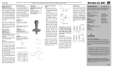
Baseefa09ATEX0281X
IECEx BAS 09.0135X
Ex de IIC T4/T6 Gb
Ex tb IIIC T130°C/T85°C Db IP66
T4/T130°C Tamb: -40°C to + 100°C
T6/T85°C Tamb: -40°C to + 50°C
0518
II 2 GD
6. LIMITATION OF REMEDY AND LIABILITY: SELLER SHALL NOT BE
LIABLE FOR DAMAGES CAUSED BY DELAY IN PERFORMANCE. THE
REMEDIES OF BUYER SET FORTH IN THIS AGREEMENT ARE EXCLU-
SIVE. IN NO EVENT, REGARDLESS OF THE FORM OF THE CLAIM OR
CAUSE OF ACTION (WHETHER BASED IN CONTRACT, INFRINGEMENT,
NEGLIGENCE, STRICT LIABILITY, OTHER TORT OR OTHERWISE), SHALL
SELLER’S LIABILITY TO BUYER AND/OR ITS CUSTOMERS EXCEED THE
PRICE TO BUYER OF THE SPECIFIC GOODS MANUFACTURED OR
SERVICES PROVIDED BY SELLER GIVING RISE TO THE CLAIM OR
CAUSE OF ACTION. BUYER AGREES THAT IN NO EVENT SHALL
SELLER’S LIABILITY TO BUYER AND/OR ITS CUSTOMERS EXTEND TO
INCLUDE INCIDENTAL, CONSEQUENTIAL OR PUNITIVE DAMAGES. THE
TERM “CONSEQUENTIAL DAMAGES” SHALL INCLUDE, BUT NOT BE
LIMITED TO, LOSS OF ANTICIPATED PROFITS, REVENUE OR USE AND
COSTS INCURRED INCLUDING WITHOUT LIMITATION FOR CAPITAL,
FUEL AND POWER, AND CLAIMS OF BUYER’S CUSTOMERS.
7. PATENTS: Subject to the limitations contained in Section 6, Seller shall
defend any suits brought against Buyer based on a claim that use of the Goods
manufactured by Seller constitutes an infringement of a valid patent of the
United States, and shall pay any damages awarded therein against Buyer,
provided that Buyer: promptly notifies Seller in writing of the filing of such suit or
the threat thereof; permits Seller to control completely the defense or compro-
mise of such claim of infringement; and provides all reasonable assistance and
cooperation requested by Seller for the defense of such suit. In the event that
only the Goods manufactured by Seller are held to be infringing in such suit and
their use is enjoined, Seller shall, at its sole option and expense, provide a
commercially reasonable alternative, including, but not limited to, procuring for
Buyer the right to continue using the Goods, replacing them with a non-
infringing product or modifying them so they become non-infringing. Buyer
agrees that Seller shall not be liable for infringement, and that Buyer shall fully
indemnify Seller therefore, if infringement is based upon the use of Goods in
connection with goods not manufactured by Seller or in a manner for which the
Goods were not designed by the Seller or if the Goods were not designed by
the Seller or if the Goods were designed by the Buyer or were modified by or for
the Buyer in a manner to cause them to become infringing.
8. TAXES: Any tax or governmental charge payable by the Seller because of
the manufacture, sale or delivery of the Goods, or provision of Services, may at
Seller's option be added to the price herein specified. The foregoing shall not
apply to taxes based upon Seller’s net income.
9. TERMS OF PAYMENT: Subject to the approval of Seller's Credit Depart-
ment, terms are F.O.B. shipping point, net 30 days from date of Seller's invoice
in U.S. currency, except for applicable milestone payments covered below or
export shipments for which Seller may require other arrangements. Freight
charges may include shipping and handling charges, and Buyer shall pay all
such charges. If any payment owed to Seller hereunder is not paid when due, it
shall bear interest at a rate 1-1/2% per month interest from the date on which it
is due until it is received and future shipments may be placed on hold. Seller
shall have the right, among other remedies, either to terminate the Agreement
or to suspend further deliveries under this and/or other agreements with Buyer
in the event Buyer fails to make any payment hereunder when due. Buyer shall
be liable for all expenses attendant to collection of past due amounts, including
attorneys' fees. Unless otherwise provided in Seller's written quotation, periodic
milestone payments shall be made by Buyer when the purchase price of this
Agreement exceeds $100,000. In such cases, invoices shall be issued by Seller
and paid by Buyer based on the following milestones: Milestone 1: 30% of price
upon acceptance of order by Seller. Milestone 2: 30% of price upon release by
Seller of approved bills of material to manufacturing for assembly. Milestone 3:
40% of price upon shipment of the Goods by Seller. Seller reserves the right to
designate additional Milestones where the Agreement provides for Services in
excess of $50,000.
10. SOFTWARE AND FIRMWARE: Notwithstanding any other provision herein
to the contrary, Seller or applicable third party owner shall retain all rights of
ownership and title in its respective firmware and software, including all copy-
rights relating to such firmware and software and all copies of such firmware
and software. Except as otherwise provided herein, Buyer is hereby granted a
nonexclusive, royalty free license to use firmware and software, and copies of
firmware and software, incorporated into the Goods only in conjunction with
such Goods and only at the Buyer’s plant site where the Goods are first used.
Buyer may negotiate with Seller separate licenses to use such copies and
firmware and software at other plant sites. Buyer’s use of certain firmware (as
specified by Seller) and all other software shall be governed exclusively by
Seller’s and/or third party owner’s applicable license terms.
11. BUYER SUPPLIED DATA: To the extent that Seller has relied upon any
specifications, information, representation of operating conditions or other data
or information supplied by Buyer to Seller (“Data”) in the selection or design of
the Goods and/or provision of the Services and the preparation of Seller's
quotation, and in the event that actual operating conditions or other conditions
differ from those represented by Buyer and relied upon by Seller, any warran-
ties or other provisions contained herein which are affected by such conditions
shall be null and void.
12. EXPORT/IMPORT: Buyer agrees that all applicable import and export
control laws, regulations, orders and requirements, including without limitation
those of the United States and the European Union, and the jurisdictions in
which the Seller and Buyer are established or from which items may be sup-
plied will apply to its receipt and use of Goods and Services. In no event shall
Buyer use, transfer, release, import, export, or re-export Goods in violation of
such applicable laws, regulations, orders, or requirements.
13. GENERAL PROVISIONS: (a) Buyer shall not assign its rights or obligations
under the Agreement without Seller's prior written consent; (b) there are no
understandings, agreements or representations, express or implied, not
specified in the Agreement; (c) no action, regardless of form, arising out of
transactions under the Agreement, may be brought by either party more than
two years after the cause of action has accrued; (d) any modification of these
terms and conditions must be set forth in a written instrument signed by a duly
authorized representative of Seller; (e) the Agreement is formed and shall be
construed, performed and enforced under the laws of the State of Missouri
(however, Buyer and Seller agree that the proper venue for all actions arising
under the Agreement shall be only in the State where the Goods involved in
such actions were manufactured; (f) The 1980 United Nations Convention on
Contracts for the International Sale of Goods does not apply to this Agreement;
(g) If any provision of the Agreement is invalid under any statute or rule of law,
such provision, to that extent only, shall be deemed to be omitted without
affecting the validity of the remainder of the Agreement; (h) Seller specifically
objects to the application of any Federal Acquisition Regulation (“FAR”) or other
governmental procurement provision or clause to the Agreement; (i) UNLESS
OTHERWISE SPECIFICALLY PROVIDED IN SELLER’S QUOTATION,
GOODS AND SERVICES HEREUNDER ARE NOT INTENDED FOR USE IN
ANY NUCLEAR OR NUCLEAR RELATED APPLICATIONS. Buyer (i) accepts
Goods and Services in accordance with the restriction set forth in the immedi-
ately preceding sentence, (ii) agrees to communicate such restriction in writing
to any and all subsequent purchasers or users and (iii) agrees to defend,
indemnify and hold harmless Seller from any and all claims, losses, liabilities,
suits, judgments and damages, including incidental and consequential damag-
es, arising from use of Goods and Services in any nuclear or nuclear related
applications, whether the cause of action be based in tort, contract or other-
wise, including allegations that the Seller's liability is based on negligence or
strict liability; (j) The rights, remedies and protections afforded to Seller under
this Agreement, including but not limited to indemnification of Seller, limitation
of remedy and liability and limited warranty shall extend to Seller and to its
affiliates, subsidiaries, or related companies performing or supplying work,
services, or products under this Agreement or any agreement into which it is
incorporated by reference; and (k) Seller does not agree to: (i) indemnify Buyer;
or (ii) name Buyer as an additional insured.
TOPWORX TERMS AND CONDITIONS OF SALE
These terms and conditions, the attendant quotation or acknowledgment, and
all documents incorporated by reference therein, binds TopWorx, Inc. hereinaf-
ter the Seller, and the buyer, hereinafter Buyer, and constitutes the entire
agreement (Agreement) between Buyer and Seller for the provision of services
(Services) and/or the sale of goods (Goods) including (except as provided in
Section 10) firmware incorporated therein.
1. PRICES: Unless otherwise specified by Seller, Seller's price for the Goods
and/or Services shall remain in effect for thirty (30) days after the date of
Seller's quotation or acceptance of the order for the Goods/Services, whichever
is delivered first, provided an unconditional, complete authorization for the
immediate manufacture and shipment of the Goods and/or provision of Ser-
vices pursuant to Seller's standard order processing procedures is received and
accepted by Seller within such time period. If such authorization is not received
by Seller within such thirty (30) day period, Seller shall have the right to change
the price for the Goods/Services to Seller's price in effect for the Goods/
Services at the time the order is released to final manufacture. Prices for Goods
do not cover storing, installing, starting up or maintaining Goods unless ex-
pressly stated in Seller’s quotation. Notwithstanding the foregoing, the price for
Goods/Services sold by Seller, but manufactured by others, shall be Seller's
price in effect at the time of shipment to Buyer.
2. DELIVERY, ORDER ACCEPTANCE AND DOCUMENTATION: All shipping
dates are approximate and are based upon Seller's prompt receipt of all
necessary information from Buyer to properly process the order. Notwithstand-
ing any provisions to the contrary in this or other documents related to this
transaction, and regardless of how price was quoted, whether FOB, FAS, CIF
or otherwise, legal title to the Goods and risk of loss thereto shall transfer to
Buyer as follows: for sales in which the end destination of the Goods is within
the United States, upon delivery to the freight carrier at the shipping point; for
sales in which the end destination of the Goods is outside of the United States,
immediately after the Goods have passed beyond the territorial limits of the
United States. Seller shall provide Buyer with that data/documentation which is
specifically identified in the quotation. If additional copies of data/documentation
or non-standard data/documentation are to be provided by Seller, they shall be
provided to Buyer at Seller's price then in effect. Data/documentation marked
as confidential or proprietary may not be reproduced or used for any purpose
other than the purpose for which it was provided and may not be disclosed to
third parties without the prior written permission of Seller.
3. EXCUSE OF PERFORMANCE: Seller shall not be liable for delays in
performance or for non-performance due to failure or interruption of computer
or telecommunication systems, acts of God, war, riot, fire, terrorism, labor
trouble, unavailability of materials or components, explosion, accident, compli-
ance with governmental requests, laws, regulations, orders or actions, or other
unforeseen circumstances or causes beyond Seller's reasonable control. In the
event of such delay, the time for performance or delivery shall be extended by a
period of time reasonably necessary to overcome the effect of the delay.
4. TERMINATION AND SUSPENSION BY BUYER: Buyer may terminate or
suspend its order for any or all of the Goods/Services covered by the Agree-
ment provided that Buyer gives Seller reasonable advance written notice of
such termination or suspension and reimburses Seller for all losses, damages,
costs and expenses arising from such termination or suspension.
5. LIMITED WARRANTY: Subject to the limitations contained in Section 6
herein, Seller warrants that the licensed firmware embodied in the Goods will
execute the programming instructions provided by Seller, and that the Goods
manufactured or Services provided by
Seller will be free from defects in materials or workmanship under normal use
and care. The foregoing warranties will apply until the expiration of the applica-
ble warranty period. All other Goods are warranted for twelve (12) months from
the date of shipment by Seller. Consumables and Services are warranted for a
period of 90 days from the date of shipment or completion of the Services.
Products purchased by Seller from a third party for resale to Buyer (“Resale
Products”) shall carry only the warranty extended by the original manufacturer.
Buyer agrees that Seller has no liability for Resale Products beyond making a
reasonable commercial effort to arrange for procurement and shipping of the
Resale Products. If Buyer discovers any warranty defects and notifies Seller
thereof in writing during the applicable warranty period, Seller shall, at its
option, correct any errors that are found by Seller in the firmware or Services or
repair or replace F.O.B. point of manufacture that portion of the Goods or
firmware found by Seller to be defective, or refund the purchase price of the
defective portion of the Goods/Services. All replacements or repairs necessitat-
ed by inadequate maintenance, normal wear and usage, unsuitable power
sources or environmental conditions, accident, misuse, improper installation,
modification, repair, use of unauthorized replacement parts, storage or han-
dling, or any other cause not the fault of Seller are not covered by this limited
warranty, and shall be at Buyer’s expense. Seller shall not be obligated to pay
any costs or charges incurred by Buyer or any other party except as may be
agreed upon in writing in advance by Seller. All costs of dismantling, reinstalla-
tion and freight and the time and expenses of Seller’s personnel and represent-
atives for site travel and diagnosis under this warranty clause shall be borne by
Buyer unless accepted in writing by Seller. Goods repaired and parts replaced
by Seller during the warranty period shall be in warranty for the remainder of
the original warranty period or ninety (90) days, whichever is longer. This
limited warranty is the only warranty made by Seller and can be amended only
in a writing signed by Seller. THE WARRANTIES AND REMEDIES SET
FORTH ABOVE ARE EXCLUSIVE. THERE ARE NO REPRESENTATIONS OR
WARRANTIES OF ANY KIND, EXPRESS OR IMPLIED, AS TO MERCHANTA-
BILITY, FITNESS FOR PARTICULAR PURPOSE OR ANY OTHER MATTER
WITH RESPECT TO ANY OF THE GOODS OR SERVICES.
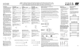
70 Series with Connection Head


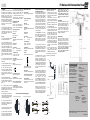 1
1
 2
2
 3
3


 TopWorx GO™ Switch Stroke-to-Go IOM 7C, 7D, 7E, 7F Owner's manual
Emerson GO™ Switch 80 Series IOM Owner's manual
 TopWorx 10 & 20 Series IOM Owner's manual
 TopWorx 30 Series IOM Owner's manual
TopWorx GO Switch 70 Series IOM Owner's manual
 TopWorx GO 7CX & 7DX IOM Stroke-To-GO IOM Owner's manual
TopWorx GO™ Switch 10 & 20 Series IOM Owner's manual
 TopWorx GO Switch 7J IOM Owner's manual
 TopWorx Slip-Lok Flyer Owner's manual
 TopWorx GO Switch Models C7, C8, H7, H8, M7, M8, R7, SV7 IOM Owner's manual


Trumeter 710 Series User guide
Aurora Centrifugal Pump Owner's manual
Eaton DH325NGKLP Operating instructions