Page is loading ...

Instructions - Parts List
Xtreme
™
Lowers
High volume lowers for protective coatings. For professional use only.
See page 3 for model information, see page 33 for maximum working pressure.
I
mportant Safety Instructions
Read all warnings and instructions in this manual.
Save these instructions.
TI8630b
Model L220C1 Lower without Filter
Model L220C2 Lower with Built-in Filter
TI8405a
311762W
EN

Related Manuals
2 311762W
Contents
Related Manuals . . . . . . . . . . . . . . . . . . . . . . . . . . . 2
Models . . . . . . . . . . . . . . . . . . . . . . . . . . . . . . . . . . . 3
Warnings . . . . . . . . . . . . . . . . . . . . . . . . . . . . . . . . . 4
Component Identification . . . . . . . . . . . . . . . . . . . . 6
Repair . . . . . . . . . . . . . . . . . . . . . . . . . . . . . . . . . . . . 7
Disassembly . . . . . . . . . . . . . . . . . . . . . . . . . . . . 7
Service Built-in Filter . . . . . . . . . . . . . . . . . . . . . 14
Parts . . . . . . . . . . . . . . . . . . . . . . . . . . . . . . . . . . . . 16
Repair Kits . . . . . . . . . . . . . . . . . . . . . . . . . . . . . . . 26
Xtreme Seals
™
Repair Kits . . . . . . . . . . . . . . . . 26
Tuff-Stack
™
Repair Kits . . . . . . . . . . . . . . . . . . 27
X-Tuff
®
Repair Kits . . . . . . . . . . . . . . . . . . . . . . 28
Kits . . . . . . . . . . . . . . . . . . . . . . . . . . . . . . . . . . . . . 29
Dimensions . . . . . . . . . . . . . . . . . . . . . . . . . . . . . . 31
Outlet Housing Mounting Hole Layout . . . . . . . . 32
Technical Data . . . . . . . . . . . . . . . . . . . . . . . . . . . . 33
Graco Standard Warranty . . . . . . . . . . . . . . . . . . . 36
Graco Information . . . . . . . . . . . . . . . . . . . . . . . . 36
Related Manuals
Component Manuals in English:
Manual Description
311164
Xtreme Packages Instructions and Parts
3A0420
XP Sprayer Operation
311238
NXT
®
Air Motor Instructions and Parts
311239
Air Control Modules for NXT Air Motors
Instructions and Parts
Xtreme Lower Repair Kits
406882
Filter Seal and Cap Conversion Kit,
Instructions-Parts
406879
XP 36cc Lower, Repair-Parts
406880
XP 48cc Lower, Repair-Parts
406990
XP 54cc Lower, Repair-Parts
406881
XP 58cc Lower, Repair-Parts
406991
XP 72cc Lower, Repair-Parts
406888
XP/Xtreme 85cc Lower, Repair-Parts
406992
XP 90cc Lower, Repair-Parts
406993
XP 97cc Lower, Repair-Parts
406889
XP/Xtreme 115cc Lower, Repair-Parts
406890
XP/Xtreme 145cc Lower, Repair-Parts
406891
XP/Xtreme 180c Lower, Repair-Parts
406892
XP/Xtreme 220cc Lower, Repair-Parts
406893
XP/Xtreme 250cc Lower, Repair-Parts
406894
XP/Xtreme 290cc Lower, Repair-Parts

Models
311762W 3
Models
Check the identification plate (ID) on your lower for the 6-digit part number of your
lower. Use the following matrix to define the construction of your lower, based on the
six digits. For example, Lower Part Number L180C1 represents the lower (L), output
volume (180), carbon steel construction (C), and no filter with Xtreme Seal
™
packing
stack (1).
To order replacement parts, see Parts, starting on page 16.
★
Models with a 5.9 in. bolt pattern; see page 32.
✿
XP proportioner models with inlet spring and no purge
valve.
*See Repair Kits, page 26, for packing material details.
† Includes rupture disc.
For maximum fluid working pressures, see
Technical Data section starting on page 33.
L 180 C 1
First Digit
Second, Third, and
Fourth Digits Fifth Digit Sixth Digit
Lower Volume (cc) Material
Integrated
Filter
Xtreme Seal
™
Packing Set*
Tuff Stack
™
Packing Set*
X-Tuff
®
Packing Set*
L
(lower)
36★
C Carbon Steel 0✿
✔
✔
48★
1
✔
54★
2
✔✔
58★
3
✔
72★
4
✔
✔
85★
7
✔
90★
8
†
✔
97★
9
†
✔
115★
145
14A★
180
18A★
220
22A★
250
25A★
290
29A★
ID
TI8405a
Not all options are available in all sizes.
Part
No. Description Packings
24N942
290 Xtreme carbon steel, with
hard chrome rod
X-Tuff Packing
Set

Warnings
4 311762W
Warnings
The following warnings are for the setup, use, grounding, maintenance, and repair of this equipment. The exclama-
tion point symbol alerts you to a general warning and the hazard symbol refers to procedure-specific risk. Refer back
to these warnings. Additional, product-specific warnings may be found throughout the body of this manual where
applicable.
WARNING
FIRE AND EXPLOSION HAZARD
Flammable fumes, such as solvent and paint fumes, in work area can ignite or explode. To help pre-
vent fire and explosion:
• Use equipment only in well ventilated area.
• Eliminate all ignition sources; such as pilot lights, cigarettes, portable electric lamps, and plastic
drop cloths (potential static arc).
• Keep work area free of debris, including solvent, rags and gasoline.
• Do not plug or unplug power cords, or turn power or light switches on or off when flammable
fumes are present.
• Ground all equipment in the work area. See Grounding instructions.
• Use only grounded hoses.
• Hold gun firmly to side of grounded pail when triggering into pail.
• If there is static sparking or you feel a shock, stop operation immediately. Do not use equipment
until you identify and correct the problem.
• Keep a working fire extinguisher in the work area.
SKIN INJECTION HAZARD
High-pressure fluid from gun, hose leaks, or ruptured components will pierce skin. This may look like
just a cut, but it is a serious injury that can result in amputation. Get immediate surgical treatment.
• Do not point gun at anyone or at any part of the body.
• Do not put your hand over the spray tip.
• Do not stop or deflect leaks with your hand, body, glove, or rag.
• Do not spray without tip guard and trigger guard installed.
• Engage trigger lock when not spraying.
•
Follow Pressure Relief Procedure in manual 311164, when you stop spraying and before clean-
ing, checking, or servicing equipment.
EQUIPMENT MISUSE HAZARD
Misuse can cause death or serious injury.
• Do not operate the unit when fatigued or under the influence of drugs or alcohol.
• Do not exceed the maximum working pressure or temperature rating of the lowest rated system
component. See Technical Data in all equipment manuals.
• Use fluids and solvents that are compatible with equipment wetted parts. See Technical Data in
all equipment manuals. Read fluid and solvent manufacturer’s warnings. For complete information
about your material, request MSDS forms from distributor or retailer.
• Check equipment daily. Repair or replace worn or damaged parts immediately with genuine man-
ufacturer’s replacement parts only.
• Do not alter or modify equipment.
• Use equipment only for its intended purpose. Call your distributor for information.
• Route hoses and cables away from traffic areas, sharp edges, moving parts, and hot surfaces.
• Do not kink or over bend hoses or use hoses to pull equipment.
• Keep children and animals away from work area.
• Comply with all applicable safety regulations.

Warnings
311762W 5
MOVING PARTS HAZARD
Moving parts can pinch or amputate fingers and other body parts.
• Keep clear of moving parts.
• Do not operate equipment with protective guards or covers removed.
• Pressurized equipment can start without warning. Before checking, moving, or servicing equip-
ment, follow the Pressure Relief Procedure in manual 311164. Disconnect power or air supply.
TOXIC FLUID OR FUMES HAZARD
Toxic fluids or fumes can cause serious injury or death if splashed in the eyes or on skin, inhaled, or
swallowed.
• Read MSDS’s to know the specific hazards of the fluids you are using.
• Store hazardous fluid in approved containers, and dispose of it according to applicable guidelines.
• Always wear impervious gloves when spraying or cleaning equipment.
PERSONAL PROTECTIVE EQUIPMENT
You must wear appropriate protective equipment when operating, servicing, or when in the operating
area of the equipment to help protect you from serious injury, including eye injury, inhalation of toxic
fumes, burns, and hearing loss. This equipment includes but is not limited to:
• Protective eyewear
• Clothing and respirator as recommended by the fluid and solvent manufacturer
•Gloves
• Hearing protection
WARNING

Component Identification
6 311762W
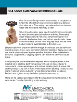
Component Identification
(Shown with Built-in Filter)
Key:
A Displacement Rod
B Packing Nut
C Throat Cartridge
D Outlet Housing
E Locking Pin
F Cylinder
G Drain/Purge Valve (not on XP Lowers)
H Inlet Housing
J Fluid Outlet
K Optional Fluid Outlet (for second spray gun; not on
XP Lowers)
L Pipe Plug (non-filtered outlet)
M Fluid Filter
N Over Pressure Rupture Disc (for 36cc, 48cc, 54cc,
58 cc, and 72cc only)
A
B
C
D
E
G
H
J
K
L
M
TI8404b
F
XP Sprayer Xtreme Lowers
A
B
C
D
E
H
L
N
F
M
r_b058C0_311762_6

Repair
311762W 7
Repair
Required Tools
• Set of adjustable wrenches
• Torque wrench
• Rubber mallet
• Arbor press
• Soft wooden block (approx. 1 square ft in size)
• Large vise with soft jaws
• Thread lubricant
• Petroleum jelly
• Anti-seize lubricant
Disassembly
Layout all removed parts in sequence to ease reassem-
bly. Clean all parts with a compatible solvent and
inspect them for wear or damage.
1. Relieve pressure. See your Xtreme Packages man-
ual (311164) for instructions.
2. Disconnect lower from motor as illustrated in your
Xtreme Packages manual (311164). Or, if you have
a cart mounted system, tip cart up to service lower
on cart.
3. For lowers with built-in filters, loosen and remove
both top filter cap (20) and bottom filter cap (26).
See Service Built-in Filter, page 14.
4. Loosen and remove inlet housing (14) from lower
cylinder (11).
5. Press inlet ball (16) out from bottom of inlet housing
(14) (take care not to damage seat (18) to remove
entire inlet ball guide assembly.
a.
For Xtreme Lowers:
Remove inlet ball, bottom
o-ring (27*), and seat. Then remove remaining
o-rings from top and bottom grooves of inlet ball
guide (15).
Repair kits are available to replace the throat (3)
and piston (4) packings, and to replace the o-rings
and cylinder seals. For best results, use all new
parts in the kit. Kit parts are marked with an aster-
isk, for example (25*). These kits can also be used
to convert the lower to different packing materials.
See the Packing Kits sections.
On model L180C7 only, shims (17) will be below
inlet ball guide (15).
F
IG
. 1:
TI8267b
20
26
TI8286a
11
14
TI8287a
}
17
27*
15
27*
14
16*
18

Repair
8 311762W
b.
For 115 and smaller XP Lowers:
Remove
spring, inlet ball, bottom o-ring, and shims. Then
remove remaining o-rings from top and bottom
grooves of inlet ball guide (15).
c.
For 145cc and larger XP Lowers:
Remove inlet
ball, bottom o-ring, and shim. Then remove
remaining o-rings from top and bottom grooves
of inlet ball guide (15).
6. Stand lower upright in large vise. Using a rubber
mallet, loosen, but do not remove packing nut (2).
7. Remove locking pin (10) from lower cylinder (11).
8. Unscrew and lift outlet housing (8) straight up off
cylinder. Be careful not to scratch displacement rod
(1).
F
IG
. 2
F
IG
. 3
}
17
27*
15
27*
14
16*
18
r_b036C0_311762_8
}
17
27*
15
27*
14
16*
18
r_b14AC0_311762_8
17
27*
43
TI8274a
2
TI8269a
10
TI8309b
8
1

Repair
311762W 9
9. Remove cartridge assembly. Remove o-ring (27* or
29*) from bottom of outlet housing (8), and then
unscrew packing nut (2) from packing cartridge (7).
Remove female gland, male gland, and v-packings
(3) from packing cartridge (7).
10. Stand lower cylinder (11) upright on a wooden
block. Using a rubber mallet or an arbor press, drive
displacement rod (1) out of the bottom until the pis-
ton comes free. Pull the rod and piston from the cyl-
inder, being careful not to scratch the rod or
cylinder.
11. Inspect outer surface of displacement rod (1) and
inner surface of lower cylinder (11) for scoring or
wear; replace if damaged.
12. Put flats of piston valve (13) in a vise. Use a wrench
to loosen displacement rod (1) from piston valve.
13. Remove displacement rod from piston valve. Be
careful that piston ball (12*) does not fall as you
separate piston valve and rod.
14. Remove glands and v-packings (4) from piston
valve (13). Inspect piston ball (12*) and piston valve
for wear or damage.
15. Clean all parts with a compatible solvent.
NOTICE
To reduce the possibility of costly damage to displace-
ment rod (1) and lower cylinder (11), first place lower
cylinder on a soft block of wood. Always use a rubber
mallet or an arbor press to drive the displacement rod
out of the lower cylinder. Never use a hammer to drive
the rod out. Damage to the rod end will shorten pump
life.
TI8467a
2
3
7
8
}
32*
Female Gland
Male Gland
TI8305a
1
11
TI8298a
1
13
TI8299a
12*
TI8300a
13
{
4
12*

Repair
10 311762W
Reassembly
1. Replace female gland on piston valve (13). Install
the five v-packings (4) one at a time with lips facing
up. Refer to the Packing Kits sections for the correct
packing order for your lower. Install the male gland.
2. Ensure there are no burrs or debris on mating
threads of displacement rod (1) and piston valve
(13). Apply anti-seize lubricant to threads and mat-
ing surfaces of displacement rod and piston valve.
3. Place flats of piston valve in a vise. Place piston ball
(12*) on piston valve.
4. Screw displacement rod (1) onto piston valve (13),
and hand tight. Then torque per table on page 13.
To convert the lower to a different packing material,
see the Packing Kits sections.
For best results, soak leather packings in oil before
reassembly.
TI8461a
{
4
13
Female Gland
Male Gland
Orient crowfoot of torque wrench at a 90° angle to
ensure accurate torque values.
NOTICE
To reduce the possibility of costly damage to displace-
ment rod (1) and lower cylinder (11), first place lower
cylinder on a soft block of wood. Always use a rubber
mallet or an arbor press to drive the displacement rod
into the lower cylinder. Never use a hammer to drive
the rod.
TI8462a
1
12*
13
Apply anti-seize
lubricant to
threads before
torquing.
TI8303a
1
13

Repair
311762W 11
5. To reinstall displacement rod (1) into lower cylinder
(11), first lubricate piston packings (4). Then, with
piston end facing down, lower rod into cylinder. Start
piston into cylinder as much as possible, then drive
rod and piston the rest of the way into the cylinder
with an arbor press or rubber mallet.
6. Lubricate inside of packing cartridge (7), outside
threads of packing nut (2), and throat packings (3).
Install packing cartridge into housing. Place male
gland in packing cartridge. Install the five v-packings
one at a time with lips facing down. Refer to the
Packing Kits sections for the correct packing order
for your lower. Install female gland.Then, reassem-
ble packing nut (2), but do not tighten.
7. Screw lower cylinder (11) onto outlet housing (8)
until it bottoms out. Use a wrench to tighten lower
cylinder. Back off as little as possible until hole in
housing lines up with flat on cylinder. Insert locking
pin (10) into cylinder.
8. Assemble inlet housing.
a.
For 115cc and smaller XP Lowers:
Install seat
(18), two shims (17), inlet ball (16), spring (43),
and one o-ring (27) into inlet housing (14).
b.
For 145cc and larger XP Lowers:
Install seat
(18), shim (17), inlet ball (16), spring (43), and
one o-ring (27) into inlet housing (14).
To convert lower to a different packing material, see
Packing Kits sections.
For best results, soak leather packings in oil before
reassembly.
TI8305a
1
11
TI8467a
2
3
7
8
}
❄
Blue o-ring for 220cc, 250cc, 290cc lowers.
32*❄
Female Gland
Male Gland
TI8278a
8
10
11
}
17
27*
15
27*
14
16*
18
r_b036C0_311762_8
43
}
17
27*
15
27*
14
16*
18
r_b14AC0_311762_8
17
27*
43

Repair
12 311762W
c.
For Xtreme Lowers:
Install inlet seat (18), inlet
ball (16), and one o-ring (27*) into inlet housing
(14).
9. Lubricate and install o-rings (27*) in top and bottom
grooves of inlet ball guide (15).
10.
On model L180C7 only,
install shims (17) into inlet
housing (14), then press inlet ball guide (15) into
inlet housing (14).
11.
On all models except L180C7,
press inlet ball
guide (15) into inlet housing (14) and install
shims (17).
12. Thread inlet housing (14) onto lower cylinder (11).
Torque to 140-150 ft-lb
(189-203 N•m).
Shims (three maximum) can be assembled either
for short ball travel or long ball travel. See F
IG
. 4 for
an example of each.
TI8290a
27*
14
16
18
{
17
15
17
{
15
ti8746a
17
{
15
ti8745a
F
IG
. 4: Shim Configuration for lowers without inlet
spring
TI8290a
}
17*
27*
15
27*
14
Shortest Ball Travel
Longest Ball Travel
TI8745a
TI8746a
◆
❖
✠
◆
Factory set configuration for optimum pump
change over.
❖
Shims can be configured to change ball travel
length. Use longer ball travel length for higher vis-
cosity fluids.
✠
Optional inlet ball spring kit available. Use to
improve change over rate with longer ball travel
configurations. See Kits, page 29, for more infor-
mation.

Repair
311762W 13
13. Using torque wrench, torque packing cartridge (7) to
outlet housing (8). Torque to 140-150 ft-lb (189-203
N•m).
14. Insert packings in correct orientation; see Parts,
page 16. Install packing nut (2) and torque to the
value in the table below.
Required Torque
15. For lowers with built-in filter, see Service Built-in
Filter, page 14, if filter needs service. Then reinstall
both top filter cap (20) and bottom filter cap (26).
16. Reconnect lower to air motor. See Xtreme Pack-
ages manual (311164).
Pump Throat Packing (2) Piston Valve (13)
L036C0
L048C0
L054C0
L058C0
25-30 ft-lb
(34 N•m)
85 ft-lb
(114 N•m)
L072C0
L085C0
L085C1
L085C2
25-30 ft-lb
(34 N•m)
125 ft-lb
(168 N•m)
L085C3
L085C4
125 ft-lb
(168 N•m)
L090C0
L097C0
L115C0
L115C1
L115C2
25 ft-lb
(34 N•m)
L115C3
L115C4
125 ft-lb
(168 N•m)
L145C0
L145C1
L145C2
L145C8
L14AC1
25 ft-lb
(34 N•m)
L145C3
L145C4
125 ft-lb
(168 N•m)
L180C0
L180C1
L180C2
L18AC1
25 ft-lb
(34 N•m)
L180C3
L180C4
L180C7
L180C9
125
(168 N•m)
L220C0
L220C1
L220C2
L22AC1
25 ft-lb
(34 N•m)
200 ft-lb
(269 N•m
L220C3
L220C4
L220C9
125 ft-lb
(168 N•m)
L250C0
L250C1
L250C2
L250C8
25 ft-lb
(34 N•m)
L250C3
L250C4
L25AC4
125 ft-lb
(168 N•m)
L290C0
L290C1
L290C2
L29AC1
24N942
25 ft-lb
(34 N•m)
L290C3
L290C4
125 ft-lb
(168 N•m)
2
(see table)
TI8279b
8
7
(Torque to 140-150 ft-lb)
TI8281b
20
26

Repair
14 311762W
Service Built-in Filter
Select models have a built-in filter in the lower housing.
Disassembly
To remove and clean the built-in filter:
1. Relieve fluid pressure.
a. Turn off sprayer motor and any feed pumps.
b. Drain all fluid pressure from sprayer. See
sprayer manual for detailed instructions.
2. Use wrench to loosen and remove top filter cap
(20).
3. Remove o-ring (59*), strainer (23), and filter support
(24).
4. Use wrench to loosen and remove bottom filter cap
(26). Remove o-rings (22*, 25*).
5. Replace o-rings (22*, 25*), strainer (23), and filter
support (24).
6. Remove pipe plug (49), and use brush or drill to
clean port as necessary.
TI8292a
20
TI8293a
59*
24
23
O-rings take a set at high pressures. Always
replace the o-rings once the filter caps have been
removed.
TI8463a
26
25*
22*
TI8747a

Repair
311762W 15
Reassembly
To reassemble the built-in filter:
1. Install o-rings (22*, 25*) onto bottom filter cap (26).
Then use wrench to reassemble and tighten bottom
filter cap. Torque to 40-60 ft-lb (52-82 N•m).
2.
Reassemble o-ring (59*) onto top filter cap (20).
Install strainer (23), and filter support (24) in top fil-
ter cap. Then use wrench to install and tighten top
filter cap. Torque to 40-60 ft-lb (52-82 N•m)
.
NOTE: 36cc through 115cc Xtreme pump lowers no lon-
ger use the short filter screens (23) or supports (24).
See page 30 for details.
NOTICE
To prevent leaking, ensure that the proper repair com-
ponents are used for the appropriate series pump.
See Filter Cap Repair Kit, 24F975, page 30, for
more information.
Lubricate all o-rings with before installation.
TI8294a
26
25*
22*
thin
medium
TI8402a
TI8464a
20
24
59*
23
thick
pin faces
up
slot is on bottom
open end
down
pin hole
faces up

Parts
16 311762W
Parts
XP Sprayer Lower Models
36cc, 48cc, 54cc, 58cc, 72cc, 85cc, 90cc, 97cc, and 115cc
19*
20
21
23
24
4
1
2
59*
}
7
3* (Throat)
2
8
10
54
26
25*
4
22*
9*
29*
11
56
12*
(Piston)
4*
{
1
{
17
18
Torque per specifications in table on page 13.
Torque to 140-150 ft-lb (189-203 N•m).
Torque to 40-60 ft-lb (52-82 N•m).
Apply lubricant to threads before assembly.
Torque to 45-55 ft-lb (61-75 N•m).
7. Thick, medium, and thin refers to the relative
cross-section thickness of the o-ring seals.
1
2
4
5
6
27*
15
43*
16*
27*
14
2
r_b036c0_311762_15
*
Parts included in repair kits (purchase separately).
S
ee Repair Kits sections.
✖
85cc - 115cc use plug.
Ensure orifice of (55) points down.
49 ✖
32*
6
1
6
5
5
1
5
✿
13
medium
thin
thin
thin
medium
thick
61
55 ✖

Parts
311762W 17
36cc, 48cc, 54cc, 58cc, and 72cc XP Models
▲
Replacement Danger and Warning labels, tags, and
cards are available at no cost.
* Parts included in repair kits (purchase separately).
† See page 30 to verify correct part numbers.
Part numbers listed are for bulk quantities. Individual
quantities are included in repair kits. See
Repair
Kits
on page 26.
Ref.
Descriptions
36cc 48cc 54cc 58cc 72cc
Qty.L036C0 L048C0 L054C0 L058C0 L072C0
1 ROD, displacement
16D458 16D459 16J900 16D460 16J901 1
2 NUT, packing
16D468 16D468 16D468 16D468 15K029 1
3* PACKINGS, stack; throat
See Repair Kits on page 26. 1
4* PACKINGS, stack; piston
See Repair Kits on page 26. 1
7 CARTRIDGE, packing, throat
16D467 16D467 16D467 16D467 16K490 1
8 HOUSING, outlet
15F659 15F659 15F659 15F659 15F659 1
9* O-RING, top cylinder; PTFE, medium (10 pack)
288067 288067 288067 288067 288067 1
10 PIN, self-locking
244826 244826 244826 244826 244826 1
11 CYLINDER, lower
16D469 16D470 16J906 16D471 16J907 1
12 BALL, piston (pack of 3)
262485 262485 262485 262485 262741 1
13 VALVE, piston
16D464 16D464 16D464 16D464 16K068 1
14 HOUSING, inlet
15F667 15F667 15F667 15F667 15F667 1
15 GUIDE, ball, inlet
16D472 16D472 16D472 16D472 16D472 1
16* BALL, inlet (pack of 3)
244899 244899 244899 244899 244899 1
17 SHIM, inlet, ball guide (pack of 9)
288064 288064 288064 288064 288064 2
18 SEAT, inlet
15F665 15F665 15F665 15F665 15F665 1
19* PLUG, throat seal (pack of 10)
247393 247393 247393 247393 247393 1
20
†
CAP, filter, top
16M461 16M461 16M461 16M461 16M461 1
21 SPRING, compression
171941 171941 171941 171941 171941 1
22*
†
O-RING, filter; thin, PTFE (10 pack)
244895 244895 244895 244895 244895 1
23 STRAINER, 30 mesh screen; see page 29 for more
options
224458 224458 224458 224458 224458 1
24 SUPPORT, filter
186075 186075 186075 186075 186075 1
25*
†
O-RING, filter; medium, PTFE (10 pack)
262484 262484 262484 262484 262484 1
26
†
CAP, filter
16M462 16M462 16M462 16M462 16M462 1
27* O-RING; foot valve, PTFE, thin (pack of 10)
288068 288068 288068 288068 288068 2
29* O-RING; cylinder bottom, PTFE, medium (pack of 10)
262512 262512 262512 262512 262512 1
30
▲
TAG, warning
172479 172479 172479 172479 172479 1
32* O-RING, PTFE, throat cartridge, medium (10 pack)
262512 262512 262512 262512 262512 1
43 SPRING, foot valve
124007 124007 124007 124007 124007 1
49 PLUG, pipe; 3/8 npt
198292 198292 198292 198292 198292 1
54 PLUG, pipe; 1/2 in.
100737 100737 100737 100737 100737 1
55 HOUSING, rupture disc assy
258962 258962 258962 258962 258962 1
56 ADAPTER, rod
15Y399 15Y399 15Y399 15Y399 15Y399 1
59*
†
O-RING, filter; thick, PTFE (10 pack)
262483 262483 262483 262483 262483 1
61 COUPLER, assembly
247167 247167 247167 247167 247167 1

Parts
18 311762W
85cc, 90cc, 97cc, and 115cc XP Models
▲
Replacement Danger and Warning labels, tags, and cards
are available at no cost.
* Parts included in repair kits (purchase separately).
† See page 30 to verify correct part numbers.
Part numbers listed are for bulk quantities. Individual quan-
tities are included in repair kits. See
Repair Kits on page
26.
Ref.
Descriptions
85cc 90cc 97cc 115cc
Qty.L085C0 L090C0 L097C0 L115C0
1 ROD, displacement
24B819 16J902 16J903 24B820 1
2 NUT, packing
15K029 15K029 15K029 15K029 1
3* PACKINGS, stack; throat
See Repair Kits on page 26. 1
4* PACKINGS, stack; piston
See Repair Kits on page 26. 1
7 CARTRIDGE, packing, throat
15F660 16K490 16K490 15F661 1
8 HOUSING, outlet
15F659 15F659 15F659 15F659 1
9* O-RING, top cylinder; PTFE, medium (10 pack)
288067 288067 288067 288067 1
10 PIN, self-locking
244826 244826 244826 244826 1
11 CYLINDER, lower
15F682 16J908 16J909 15F656 1
12 BALL, piston (pack of 3)
288065 288065 288065 288065 1
13 VALVE, piston
24B818 24B818 24B818 24B817 1
14 HOUSING, inlet
15F667 15F667 15F667 15F667 1
15 GUIDE, ball, inlet
16D472 16D472 16D472 16D472 1
16* BALL, inlet (pack of 3)
244899 244899 244899 244899 1
17 SHIM, inlet, ball guide (pack of 9)
288064 288064 288064 288064 2
18 SEAT, inlet
15F665 15F665 15F665 15F665 1
19* PLUG, throat seal (pack of 10)
247393 247393 247393 247393 1
20
†
CAP, filter, top
16M461 16M461 16M461 16M461 1
21 SPRING, compression
171941 171941 171941 171941 1
22*
†
O-RING, filter; thin, PTFE (10 pack)
244895 244895 244895 244895 1
23 STRAINER, 30 mesh screen; see page 29 for more options
224458 224458 224458 224458 1
24 SUPPORT, filter
186075 186075 186075 186075 1
25*
†
O-RING, filter; medium, PTFE (10 pack)
262484 262484 262484 262484 1
26
†
CAP, filter
16M462 16M462 16M462 16M462 1
27* O-RING; foot valve, PTFE, thin (pack of 10)
288068 288068 288068 288068 2
29* O-RING; cylinder bottom, PTFE (pack of 10)
256512 medium, 288068 thin
288068 262512 262512 288068 1
30
▲
TAG, warning
172479 172479 172479 172479 1
32* O-RING, PTFE, throat cartridge (10 pack)
256512 medium, 288068 thin
288068 262512 262512 288068 1
43 SPRING, foot valve
124007 124007 124007 124007 1
49 PLUG, pipe; 3/8 npt
198292 198292 198292 198292 1
54 PLUG, pipe; 1/2 in.
100737 100737 100737 100737 1
55 PLUG, pipe, 3/8 npt, hex hd
198292 198292 198292 198292 1
56 ADAPTER, rod
1
59*
†
O-RING, filter; thick, PTFE (10 pack)
262483 262483 262483 262483 1
61 COUPLER, assembly
247167 247167 247167 247167 1

Parts
311762W 19
XP Sprayer Lower Models
145cc, 180cc, 220cc, 250cc, and 290cc
19*
20
21
23
24
4
1
2
59*
}
7
3* (Throat)
2
8
10
54
26
25*
4
22*
9*
29*
11
56
12*
(Piston)
4*
{
1
14
2
Torque per specifications in table on page 13.
Torque to 140-150 ft-lb (189-203 N•m).
Torque to 40-60 ft-lb (52-82 N•m).
Apply lubricant to threads before assembly.
Torque to 45-55 ft-lb (61-75 N•m).
7. Thick, medium, and thin refers to the relative
cross-section thickness of the o-ring seals.
1
2
4
5
6
{
17
27*
15
43*
16*
27*
17
27*
18
r_b036c0_311762_15
* Parts included in repair kits (purchase separately).
See Repair Kits sections.
49 ✖
6
1
6
5
5
1
5
medium
thin
medium
thick
thin
thin
thin
61
55
13
32*❄
❄
Blue o-ring for 220, 250, and 290 lowers.

Parts
20 311762W
145cc, 180cc, 220cc, 250cc, and 290cc XP Models
▲
Replacement Danger and Warning labels, tags, and cards
are available at no cost.
* Parts included in repair kits (purchase separately).
† See page 30 to verify correct part numbers.
Part numbers listed are for bulk quantities. Individual quan-
tities are included in repair kits. See
Repair Kits on page
26.
Ref.
Descriptions
145cc 180cc 220cc 250cc 290cc
Qty.L14AC0 L18AC0 L22AC0 L25AC0 L29AC0
1 ROD, displacement
24B821 24B822 24B823 24B824 24B825 1
2 NUT, packing
15K030 15K031 15K031 15K031 15K031 1
3* PACKINGS, stack; throat
See Repair Kits on page 26. 1
4* PACKINGS, stack; piston
See Repair Kits on page 26. 1
7 CARTRIDGE, packing, throat
197325 197326 197327 197328 197327 1
8 HOUSING, outlet
16E151 16E151 16A763 16A763 16A763 1
9* O-RING, top cylinder; PTFE, medium (10 pack)
244892 244892 244893 244893 244893 1
10 PIN, self-locking
244826 244826 244826 244826 244826 1
11 CYLINDER, lower
197315 197316 197317 197318 197319 1
12 BALL, piston (pack of 3)
253029 253029 244898 244898 244899 1
13 VALVE, piston
24B826 24B827 24B828 24B829 24B830 1
14 HOUSING, inlet
197303 197303 197304 197304 197304 1
15 GUIDE, ball, inlet
198646 198646 198647 198647 198647 1
16* BALL, inlet (pack of 3)
245128 245128 253030 253030 253030 1
17 SHIM, inlet, ball guide (pack of 9)
244855 244855 244856 244856 244856 3
18 SEAT, inlet
196358 196358 197344 197344 197344 1
19* PLUG, throat seal (pack of 10)
247394 247394 247395 247395 247395 1
20
†
CAP, filter, top
16M461 16M461 16M461 16M461 16M461 1
21 SPRING, compression
171941 171941 171941 171941 171941 1
22*
†
O-RING, filter; thin, PTFE (10 pack)
244895 244895 244895 244895 244895 1
23 STRAINER, 30 mesh screen; see page 29 for more options
224458 224458 224458 224458 224458 1
24 SUPPORT, filter
186075 186075 186075 186075 186075 1
25*
†
O-RING, filter; medium, PTFE (10 pack)
262484 262484 262484 262484 262484 1
26
†
CAP, filter
16M462 16M462 16M462 16M462 16M462 1
27* O-RING; foot valve, PTFE, thin (pack of 10)
244890 244890 244894 244894 244894 3
29* O-RING; cylinder bottom, PTFE, thin (pack of 10)
244890 244890 244894 244894 244894 1
30
▲
TAG, warning
172479 172479 172479 172479 172479 1
32* O-RING, PTFE, throat cartridge, thin (10 pack)
244890 244890 244891 244891 244891 1
43 SPRING, foot valve
116801 116801 116802 116802 116802 1
49 PLUG, pipe; 3/8 npt
198292 198292 198292 198292 198292 1
54 PLUG, pipe; 1/2 in.
100737 100737 100737 100737 100737 1
55 PLUG, pipe; 3/8 npt
198292 198292 198292 198292 198292 1
59*
†
O-RING, filter; thick, PTFE (10 pack)
262483 262483 262483 262483 262483 1
61 COUPLER, assembly
244819 244819 244819 244819 244819 1
/