Page is loading ...

GX2335S Owner’s Manual page 31
Horizon
GX2335S NOVA+
25 Watts VHF/FM
Marine Transceiver
Owner’s Manual
W
X
SCAN
IC
A
/B
M
E
M
LAMP
H
/L
CALL
U I C
SCMB
SQL VOL
HOLD ON/OFF
U
S
A
H
I

page 32 Owner’s Manual GX2335S
TABLE OF CONTENTS
FCC NOTICE .......................................................................................................... 1
GENERAL INFORMATION .................................................................................... 2
INTRODUCTION .................................................................................................... 2
FCC/ INDUSTRY CANADA INFORMATION .......................................................... 2
ACCESSORIES ...................................................................................................... 3
PACKING LIST ....................................................................................................... 3
OPTIONS ................................................................................................................ 3
INSTALLATION...................................................................................................... 4
FREQUENCY AND DEVIATION TESTS ................................................................ 4
LOCATION.............................................................................................................. 4
INSTALLATION USING REGULAR MOUNTING BRACKET ................................. 6
OPTIONAL MOUNTING KITS ................................................................................ 6
ELECTRICAL CONNECTIONS .............................................................................. 7
CONTROLS AND INDICATORS............................................................................ 8
CONTROLS AND CONNECTIONS ........................................................................ 8
INDICATORS ........................................................................................................ 13
OPERATION......................................................................................................... 14
RECEPTION ......................................................................................................... 14
TRANSMISSION................................................................................................... 14
TRANSMIT TIME - OUT TIMER (TOT) ................................................................ 14
SIMPLEX/DUPLEX CHANNEL USE .................................................................... 15
USA, CANADA, AND INTERNATIONAL MODE .................................................. 15
WEATHER CHANNELS ....................................................................................... 15
NORMAL SCANNING........................................................................................... 15
PRIORITY SCANNING ......................................................................................... 16
WEATHER ALERT ............................................................................................... 16
EMERGENCY CHANNEL 16................................................................................ 17
CHANNEL 9 .......................................................................................................... 17
OPERATING ON CHANNEL 13 ........................................................................... 17
OPERATING ON CHANNEL 67 ........................................................................... 17
CHANNEL A/B INSTANT CALL............................................................................ 18
Programming .................................................................................................. 18
Operation ........................................................................................................ 19
VOICE SCRAMBLER ........................................................................................... 19
Programming .................................................................................................. 19
Operation with voice scrambler ...................................................................... 20
RESETTING THE TRANSCEIVER’S MICROPROCESSOR ............................... 21
RAM MIC OPERATION ........................................................................................ 22
RAM MIC CONTROLS AND CONNECTIONS ..................................................... 22
INDICATORS ........................................................................................................ 24
INTERCOM OPERATION..................................................................................... 25
Communication............................................................................................... 25
Calling............................................................................................................. 26
MAINTENANCE ................................................................................................... 27
REPLACEMENT PARTS ...................................................................................... 27
TROUBLESHOOTING CHART ............................................................................ 28
SPECIFICATIONS ................................................................................................ 29
GENERAL ............................................................................................................. 29
TRANSMITTER .................................................................................................... 29
RECEIVER............................................................................................................ 29

GX2335S Owner’s Manual page 1
FCC NOTICE
NOTICE
Unauthorized changes or modifications to this equipment may void
compliance with FCC Rules. Any change or modification must be
approved in writing by Standard Communications Corp.
NOTICE
This equipment has been tested and found to comply with the limits for
a Class B digital device, pursuant to Part 15 of the FCC Rules. These
limits are designed to provide reasonable protection against harmful
interference in a residential installation. This equipment generates,
uses and can radiate radio frequency energy and, if not installed and
used in accordance with the instructions, may cause harmful
interference to radio communications. However, there is no guarantee
that interference will not occur in a particular installation. If this
equipment does cause harmful interference to radio or television
reception, which can be determined by turning the equipment off and
on, the user is encouraged to try to correct the interference by one or
more of the following measures:
— Reorient or relocate the receiving antenna.
— Increase the separation between the equipment and receiver.
— Connect the equipment into an outlet on a circuit different from
that to which the receiver is connected.
— Consult the dealer or an experienced radio/TV technician for
help.

page 2 Owner’s Manual GX2335S
1 GENERAL INFORMATION
1.1 INTRODUCTION
The Standard Communications Corp. (SCC) GX2335S Nova+ is a VHF/FM
transceiver designed for use in the frequency range of 156.025 to 163.275
MHz. It requires 13.8V for operation and has a switchable RF output power
of 1 watt or 25 watts.
The transceiver is capable of intercom operation with the use of an
optional CMP23 (full remote-control speaker/microphone with display).
The transceiver operates on all currently-allocated marine channels which
are switchable for use with either USA, International, or Canadian
regulations. It has an emergency channel 16 which can be immediately
selected from any channel by pressing the red 16/9 key. Weather channels
can also be accessed immediately by pressing the WX key with channel
selection.
The transceiver is supplied with a removable speaker/microphone. Other
features of the transceiver include: scanning, priority scanning and faulty
antenna indication. An optional CVS240 voice scrambler can also be
installed for privacy of communications.
1.2 FCC/ INDUSTRY CANADA INFORMATION
The following data pertaining to the transceiver is necessary to fill out the
license application.
Type Acceptance ................................................................... FCC Part 80
Output Power ..........................................1 Watt (low) and 25 Watts (high)
Emission...................................................................................... 16K0F3E
Frequency Range ............................................... 156.025 to 163.275 MHz
FCC Type Number ...................................................................... APV0597
Industry Canada Type Approval ..................................... 363822194ALVC
Additional FCC and Industry Canada data, including licensing
requirements, are contained in the companion document titled
OWNER’S MANUAL SUPPLEMENT. The document also contains
charts for VHF channel assignments, transceiver procedures,
maintenance, factory service information, and warranty data.

GX2335S Owner’s Manual page 3
2 ACCESSORIES
2.1 PACKING LIST
When the package containing the transceiver is first opened, please check
it for the following contents:
• GX2335S Nova+ Transceiver (White/Black)
• CMP847W+/B+ (White/Black) Microphone (attached to the
transceiver) and hanger kit
• Open-Frame Mounting Bracket and attaching hardware
• DC23A Dust Cover
• Spare Fuse (6 A, 250 V )
• Owner’s Manual
• Owner’s Manual Supplement
• Quick-Reference Card
2.2 OPTIONS
CMB14 .........................................................Straight Flush-Mount Bracket
CMB15 .......................................................... Angled Flush-Mount Bracket
CMP23 ........................................ Remote-Access Microphone (RAM Mic)
CAW23........................................................ Extension Cable for RAM Mic
CAW2340....................................................CMP847 Mic Extension Cable
101S............................................................................. Extension Speaker
201S............................................................................. Extension Speaker
201SZ...................................................... Flush Mount Extension Speaker

page 4 Owner’s Manual GX2335S
3 INSTALLATION
3.1 FREQUENCY AND DEVIATION TESTS
FCC Regulations require that the radio’s deviation and frequency be tested
before initial installation or operation. This test should be performed by a
Certified Marine Technician.
3.2 LOCATION
1. The radio can be mounted at any angle. Choose a mounting location
that:
• is far enough from any compass to avoid erroneous compass reading
due to the speaker magnet
• provides protection from sea spray and rain
• provides accessibility to the front panel controls
• allows connection to a power source and an antenna
• has nearby space for installation of a microphone hanger
• antenna can be mounted at least 3 feet from radio
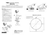
2. After the location is determined, choose the viewing angle of the front
panel. If the transceiver is mounted overhead, it is probably preferable
to tilt the face down for better viewing. If it is mounted below eye level
on a flat surface, it is probably preferable to tilt the face upward. The
face can be tilted up or down as illustrated in Figure 1.
To change the viewing angle:
a. Remove the four screws on the rear sleeve case of the transceiver.
b. Push the transceiver from the rear towards the front of the sleeve case
and remove it.
Figure 1. Viewing Angles

GX2335S Owner’s Manual page 5
NOTE
Try to keep the rectangular gasket that is between the sleeve case and
the transceiver attached to the sleeve case. If it is removed during this
procedure, or adheres to the transceiver case instead of to the sleeve
case, it must be repositioned with care. Improper positioning will cause
a defective moisture seal between the transceiver and the sleeve
case. Water can then enter and damage the transceiver.
c. If the rectangular gasket between the sleeve case and the transceiver is
removed or becomes detached from the sleeve case, refer to Figure 2
for correct installation. The key to successful orientation is the triangle
mark on the gasket. It should be on the long side of the sleeve case.
3. Install the radio following the procedure in the next section.
TRIANGLE
MARK
GASKET
SIDE B
(SHORT SIDE)
SIDE A
(LONG SIDE)
SLEEVE CASE
Figure 2. Placement of Moisture-sealing Gasket

page 6 Owner’s Manual GX2335S
3.3 INSTALLATION USING REGULAR MOUNTING
BRACKET
1. Mount the bracket using the washers, nuts, and long hex head bolts.
2. Position the radio within the bracket arms, matching the radio notches
to achieve the desired positioning.
3. Secure the radio to the bracket knobs as shown in Figure 3.
3.4 OPTIONAL MOUNTING KITS
Optional mounting kits for the transceiver are:
CMB14 Angled Mount
CMB15 Straight Mount
These mounts are shown in Figure 4. Instructions and hardware are
included in each mounting kit.
Figure 3. Regular Mounting Bracket
Figure 4. Optional CMB14 and CMB15 Mounting Brackets

GX2335S Owner’s Manual page 7
3.5 ELECTRICAL CONNECTIONS
CAUTION
Improper polarity connections will damage the radio!
Connect the power cord and antenna to the radio. Antenna and Power
Supply connections are as follows (see Figure 5):
1. Mount the antenna at least 3 feet away from the radio. At the rear of
the radio, connect the antenna cable. It must have a SO-239
connector. RG-8/U coaxial cable must be used if the antenna is 25
feet or more from the radio. RG58 cable can be used for distances less
than 25 feet.
2. Connect the red power cord to a 13.8 VDC ± 20% power source.
Connect the black power cord to negative ground.
3. If an optional remote extension speaker is to be used, connect it at this
time. Connect the RCA phono plug to the external speaker jack of the
transceiver.
4. It is advisable to have a Certified Marine Technician check the power
output and the standing wave ratio of the antenna after installation.
Figure 5. General Installation
WX
S
C
A
N
IC
A/B
M
EM
L
A
M
P
H/L
C
A
L
L
U
I
C
S
C
M
B
S
Q
L
V
O
L
P
U
S
H
O
N
/
O
F
F
U
S
A
H
I
Optional Speaker
Antenna
Water proof
Deck Outlet
Power Source
Black
Red
Fuse

page 8 Owner’s Manual GX2335S
4 CONTROLS AND INDICATORS
NOTE
This section defines each control of the transceiver. See Figure 6 for
location of controls. For detailed operation instructions refer to chapter
5 of this manual.
4.1 CONTROLS AND CONNECTIONS
q POWER SWITCH/VOLUME CONTROL
To turn the power on or off, press and hold this knob for 3 seconds,
and sets the audio volume. When power is turned on, the transceiver is
set to the priority channel.
Secondary Use
When the transceiver is turned on while the SCAN and WX keys are
held down, the internal microprocessor is reset. This clears memory
and all user-programmed settings, such as scan memory, priority scan
assignments, and A/B channel assignments. This condition is known as
the default condition, the same as when shipped from the factory. For a
list of these defaults, see the section on Resetting the Transceiver’s
Microprocessor.
w SQUELCH CONTROL (SQL)
Sets the point at which random noise on the channel does not activate
the audio circuits but a received signal does. This point is called the
squelch threshold. Further adjustment of the squelch control will
degrade reception of wanted transmissions.
e CHANNEL SELECTOR KNOB
Rotary knob used to select channels. The CH key on the microphone
can also be used to select channels.
Secondary Use
While holding down the SCAN Key and rotating the rotary knob,
you can confirm memory channels for scanning.

GX2335S Owner’s Manual page 9
Figure 6. Controls and Connectors
SPK
MIC
ANT
DC
PWR
PWR UP CH
WX
SCAN
IC
A/B
MEM
LAMP
H/L
CALL
U I C
SCMB
SQL VOL
HOLD ON/OFF
q
w
e
r
t
y
u
i
o
!0
!1
!2
!3
!4

page 10 Owner’s Manual GX2335S
r KEY PAD
16/9 Key
Immediately recalls channel 16 from any channel location. Holding
down this key recalls channel 9.
Secondary use
Please see secondary use for the WX key and the MEM key.
WX Key
Immediately recalls a weather channel from any channel.
Secondary use
1. Holding down the
16/9
key while pressing the WX key, changes the
mode from USA to International or Canadian.
2. Holding down the WX and SCAN key while turning the power on,
resets the microprocessor and erases scan channels from
memory. This clears the memory and establishes the factory-set
defaults. For a list of these defaults, see the section on Resetting the
Transceiver’s Microprocessor.
SCAN Key
Starts and stops scanning programmed channels. Refer to normal
scanning and priority scanning of sections 5.8/5.9 for details of
operation. Neither scan will start if no channel has been stored in
memory. Look for MEM adjacent to the channel number to see if the
channel is in memory (also see MEM key).
IMPORTANT- There is only one priority channel. However, it can be
assigned as one of the following four channels: Ch 09, Ch 16, Ch A, or
Ch B. The priority channel is marked with a P on the LCD.
IC Key
The IC key operates when the optional RAM Mic connected. Refer to
section 6 for details of operation.
A/B Key
Immediately recalls two user assigned channels from any channel.
Secondary Use
1. Holding down the A/B key and pressing the MEM key, deletes the
displayed channel A or B.
2. Please see secondary use for Rotary knob.

GX2335S Owner’s Manual page 11
LAMP Key
Pressing this key, changes the brightness (3 levels) of the back light for LCD
and keypad.
Secondary use
During voice scrambler setup (If the optional CVS240 Voice Scrambler
module installed), the LAMP key is used to deselect a channel that had
been selected for voice scrambler use.
MEM Key
Memorizes the selected channel into the transceiver’s scan memory for
scanning. When pressed again, DELETES the channel from the scan
memory.
Secondary use
1. Assigns the priority channel. While holding down the 16/9 key, each
press of the MEM key will cause the display to toggle through the 4
channels that can be selected as a priority channel: A, B, 16, and 9.
When the 16/9 key is released, the channel currently displayed will
be the priority channel.
2. The MEM key is also used to read Voice Scramble (VS) codes into
memory, or delete Voice Scramble (VS) codes from memory (only if
the CVS240 scrambler is installed.)
H/L Key
Toggles between high and low power. Does not operate on “low power
only” and transmission-inhibit channels. When pressed and held while
the transceiver is on channel 13 or 67, the power will temporarily go high.
This key has the same function as the PWR UP key on the microphone.
t MICROPHONE JACK
Connects a microphone to the transceiver.
y ANTENNA JACK
Connects an antenna to the transceiver. Use a marine VHF antenna
with an impedance of 50 ohms.
u EXTERNAL SPEAKER JACK
Connects an external speaker to the transceiver. Use a speaker with an
impedance of 4 or 8 ohms, with an RCA phono plug.

page 12 Owner’s Manual GX2335S
i RAM MIC CONNECTOR
Connects the remote access microphone RAM Mic. Refer to section 6
for the details of operation.
o DC INPUT CABLE
Connects the transceiver to a DC power supply of 13.8 V.
!0 PTT (Push-To-Talk) SWITCH
Keys the transmitter when the transceiver is in radio mode. If the
transceiver is in the intercom operation mode, it activates the
microphone for the intercom.
!1 SPEAKER/MICROPHONE
Transmits the voice message and also functions as a speaker.
!2 PWR UP KEY
Momentarily selects high power on USA and Canadian channel 13 and
USA channel 67 only.
!3 CH KEY
This key has the same function as the Channel Selector knob on the front
panel of the transceiver. It can increase or decrease the channel numbers,
depending on whether up or down arrow on the key is pressed.
!4 MICROPHONE HANGER
When the microphone is placed on a battery-grounded hanger, the
transceiver automatically switches to channel 16. This feature may be
disabled by either hanging the microphone in a non-grounded hanger or
by performing the following procedure:
a. Remove the 4 screws on the rear of the microphone and remove the
rear case.
b. Cut or remove the black wire attached to the microphone hanger on
the rear case.
c. Reinstall the rear case.
NOTE
Microphone Hanger feature is disabled when the RAM Mic is connected.

GX2335S Owner’s Manual page 13
4.2 INDICATORS
USA/INTL/CAN Indicator
Indicates the mode of operation.
WX Indicator
Indicates a weather channel.
HI/LO Indicator
Indicates the power setting. “HI” indicates 25 watts and “LO” indicates 1
watt.
S / D Indicator
Indicates simplex “S” or duplex “D” mode. See Section 5.4.
MEM Indicator
Indicates that the channel is memorized in the transceiver’s memory for
scanning.
A Indicator
Indicates a simplex channel in USA or Canadian mode whose counterpart
in the International mode is a duplex channel.
VS Indicator
Indicates that the voice scrambler (if installed) is in use.
EXP Indicator
Indicates an expansion channel. Expansion channels are presently not
allowed by the FCC. Use of this feature prior to FCC allocation may result in
a fine.
7-SEGMENT (I) Display
Indicates the voice scrambler code form “000” to “127” (only when a
CVS240 scrambler is installed and activated). Also used to display “P” for
priority channel and “A” and “B” for A/B channels.
7-SEGMENT (ll) Display
Indicates the channel number in use. In the Intercom mode, indicates “IC”.
CAN
USA
INTL
EXP
MEM
HI
LO
S
TX
VS
WX
(I) (II)

page 14 Owner’s Manual GX2335S
5 OPERATION
5.1 RECEPTION
1. After the transceiver has been installed, ensure that the power supply
and antenna are properly connected.
2. Press the POWER SWITCH on.
3. Turn the SQUELCH CONTROL knob fully counterclockwise. This
state is known as “squelch off”.
4. Turn up the volume until noise or audio from the speaker is at a
comfortable level.
5. Turn the squelch control knob until the random noise just disappears.
This state is known as the “squelch threshold.”
6. To turn on the backlight for the display, press the LAMP key. Each
press of the LAMP key changes the intensity (bright, dim and off) .
7. Rotate the CHANNEL SELECTOR KNOB to select the desired
channel. Refer to the channel chart in the OWNER’S MANUAL
SUPPLEMENT for available channels.
8. When a message is received, adjust the volume to the desired
listening level. The “BUSY” indicator in the LCD is displayed indicating
that the channel is being used.
5.2 TRANSMISSION
1. Perform steps 1 through 7 of RECEPTION.
2. Before transmitting, monitor the channel and ensure it is clear. THIS IS
AN FCC REQUIREMENT!
3. Press the PTT (push-to-talk) switch. The TX indicator on the LCD is displayed.
4. Speak slowly and clearly into the microphone, hold the microphone
about 1/2 inch away from your mouth.
5. When the transmission is finished, release the PTT switch.
6. Refer to the OWNER’S MANUAL SUPPLEMENT for standard
transceiver operating procedures.
5.3 TRANSMIT TIME - OUT TIMER (TOT)
With the PTT switch on the microphone held down, transmit time is limited to
5 minutes. This prevents unintentional transmissions. About 10 seconds
before automatic transmitter shutdown, a warning beep will be heard from
the speaker(s). The transceiver will then automatically go to receive mode,
even if the PTT switch is continually held down. Before transmitting again,
the PTT switch must first be released and then pressed again. Also note that
the PTT switch is ineffective while the microphone is in its grounded hanger.

GX2335S Owner’s Manual page 15
5.4 SIMPLEX/DUPLEX CHANNEL USE
Refer to the OWNER’S MANUAL SUPPLEMENT for instructions on use of
simplex and duplex channels.
NOTE
All channels are factory-programmed in accordance with FCC (USA),
Industry Canada (Canada), and International regulations, Mode of
operation cannot be altered from simplex to duplex or vice-versa.
5.5 USA, CANADA, AND INTERNATIONAL MODE
1. To change the modes, hold the 16/9 key and press the WX key. The
mode changes from USA to International to Canada with each press of
the WX key.
2. “USA” will be displayed on the LCD for the USA mode, “INTL” will be
displayed for International mode, and “CAN” will be displayed for
Canadian mode.
3. Refer to the OWNER’S MANUAL SUPPLEMENT for allocated
channels in each mode.
5.6 WEATHER CHANNELS
1. To receive a weather channel, press the WX key from any channel.
The transceiver will go to the last selected WX channel.
2. Rotate the CHANNEL SELECTOR KNOB, or press the CH key on the
microphone to go to another weather channel.
3. To exit from the weather channels, press the WX key. The transceiver
returns to the channel it was on prior to a weather channel.
5.7 NORMAL SCANNING
1. Adjust the SQUELCH CONTROL just until background noise
disappears.
2. Select a desired channel to be scanned using the CH key or CHANNEL
SELECTOR KNOB. Press the MEM key to program the channel into the
transceiver’s memory. “MEM” is displayed on the LCD.
3. Repeat step 2 for all the desired channels to be scanned.
4. To review channels programmed into scan memory, press and hold
the SCAN key and then rotate the channel selector knob. A
programmed channel will be displayed with each position change of
the channel selector knob.

page 16 Owner’s Manual GX2335S
5. To start scanning, press the SCAN key.
Scanning will proceed from the lowest to
the highest programmed channel number
and will stop on a channel when a
transmission is received.
6. To stop scanning, press the SCAN, 16/9, WX, or PTT key.
7. To DELETE a channel from the transceiver’s memory, press the MEM
key again while the memorized channel is displayed on the LCD.
“MEM” will be deleted from the LCD.
5.8 PRIORITY SCANNING
1. The following channels can be set as the priority channel; 16, 09, and
A or B preset channels. To set the priority channel, press and hold the
16/9 key and press the MEM key. The channel will change from 16 to
09 to A or B preset channel with each press of the MEM key. The
displayed channel is set to the priority channel.
2. For priority scanning, hold down the SCAN key at least 1 second
during normal scanning, Scanning will proceed between the
memorized channels and the priority channel. The priority channel will
be scanned after each programmed channel.
3. For example, channels 06, 07, 08 are memorized in the transceiver’s
memory, Priority scanning will proceed in the following sequence:
3. Even when the transceiver stops and listens to the signal of a
programmed channel, the transceiver will DUAL WATCH between this
channel and the priority channel.
5.9 WEATHER ALERT
In the event of extreme weather disturbances such as storms and
hurricanes, the NOAA (National Oceanic and Atmospheric Administration)
sends a weather alert accompanied by a 1050 Hz tone and subsequent
weather report on one of the weather channels. The transceiver is capable
of receiving this alert if the following is performed:
CH06
Priority
channel
CH07 CH08
Priority
channel
Priority
channel
NOVA+ RAM MIC

GX2335S Owner’s Manual page 17
1. Program weather channels into the transceiver’s memory for scanning.
Follow the same procedure as for regular channels under Section 5.6.
2. Press the SCAN key once to start memory scanning or hold down the
SCAN key during memory scanning to start priority scanning.
3. The programmed weather channels will be scanned along with the
regular programmed channels. However, scanning will not stop on a
normal weather broadcast.
4. When an alert is received on a weather channel, scanning will stop
and the transceiver will emit a loud intermittent beep to alert user of a
NOAA broadcast.
5. Press the WX key to stop the alert tone and receive the weather report.
5.10 EMERGENCY CHANNEL 16
1. To select the emergency channel, press the 16/9 key from any
channel.
2. Transmit your emergency signal in the same manner as on regular
channels. If you cannot contact anyone on channel 16, switch to
another channel.
3. To revert to the previous channel from channel 16 press the 16/9 key.
4. See the OWNER’S MANUAL SUPPLEMENT for additional
emergency operating practices.
5.11 CHANNEL 9
Channel 9 is used as a hailing channel for initial, non-emergency contact with
other vessels. Hold down the 16/9 key for 1 second or more to select channel 9.
5.12 OPERATING ON CHANNEL 13
Channel 13 is used at docks and bridges and for maneuvering in port.
Messages on this channel must concern navigation only, such as meeting and
passing in restricted waters. Messages must be short and use low power.
In emergencies and when approaching blind river bends, high power is
allowed. Press and hold the PWR UP key on the microphone or the H/L key
to temporarily switch to high power.
5.13 OPERATING ON CHANNEL 67
When channel 67 is used for navigational bridge-to-bridge traffic between
ships, high power may be temporarily used by pressing and holding the
PWR UP key on the microphone or the H/L key.

page 18 Owner’s Manual GX2335S
5.14 CHANNEL A /B INSTANT CALL
There could be two “calling channels” used by an organization. But USA
channels 9 and 16, and WX channels should not be assigned as A or B
channels because they are readily available with the 16/9 and WX keys. If
the A/B key is pressed and no channel A has been assigned, the LCD will
display— and no channel number will be present.
5.14.1 Programming
1. Turn on the transceiver.
2. Press the A/B key. The blinking letter A will appear on the display, and
dashes “—” indicate that no channel has been designated Channel A.
3. Rotate the channel knob until the desired channel number is
displayed.
4. With the desired channel number displayed, press the MEM key once.
The “A” will stop blinking, indicating that the displayed channel is now
designated Channel A.
5. Press the A/B key again. The blinking letter “b” will appear on the
display, and dashes “—” indicate that no channel has been designated
Channel B.
6. Rotate the CHANNEL SELECTOR knob until the desired channel
number is displayed.
7. With the desired channel number displayed, press the MEM key once.
The “b” will stop blinking, indicating that the displayed channel is now
designated Channel B.
USA
HI
USA
LO
L
USA
L
USA
LO
NOVA+ RAM Mic
NOVA+ RAM Mic
NOVA+ RAM Mic
/