
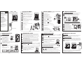
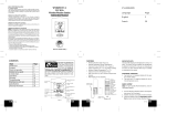
BUTTON PLACEMENT
1
6
7
8
9
2
3
4
5
MIN/-/MIN: shows minimum temperature;
adjusts clock, alarm, and temperature alarm
values
C/F: changes House Code and Channel Code;
selects °C or °F
SET: activates SET function
Battery Compartment
LCD Screen
ALARM /(°C/°F): toggles between °C and °F,
12 and 24 hour format, and alarm ON and OFF;
disables temperature alarms
CHN: scrolls through local and remote
channels (1 to 4);
HOUR/+/MAX: shows maximum temperature;
adjusts clock, alarm, and temperature alarm
values
MODE/SNOOZE: scrolls through the
clock, alarm, and (upper & lower) temperature
alarm modes; snooze for alarm
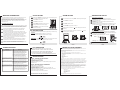
GETTING STARTED
Remove battery cover
Set up the transmitter(s) setting up the receiverbefore
Remove battery cover
2 AA size batteries (included)
2 AA size batteries (included)
setting up the transmitter
1
*
1
The temperature will appear on the LCD screen
House code will blink for 8 seconds
2
2
3
3
4
5
6
7
8
9
10
Select House code (1-15) by pressing C/F
Press SET
Press SET
Channel code will blink for 8 seconds
Select Channel code (1-4) by pressing C/F
* If you have multiple transmitters for a single receiver,
set each transmitter to the House codesame
* If you have multiple transmitters for a single receiver,
set each transmitter to a Channel codedifferent
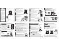
Min and Max Temperature
Temperature Trend
WS222 Receiver
WT440 Remote Transmitter
TEMPERATURE DISPLAY
A
B
*
The trend indicator shows the trend of the temperature
in the past half-hour interval.
Example:
The following indicates that the
temperature is rising.
Arrow Indicator
Rising
Steady
Falling
Trend
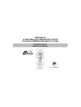
WS222 + WT440
Wireless Weather Station
OWNER’S
MANUAL
setting up the receiver
Synchronized!!!
1
1
1
2
2
3
4
WIRELESS TRANSMISSION
Automatic Learn Function:
Manual Learn Function (Remote Signal Search):
The learn function starts automatically and runs for approximately
3 minutes when batteries are first installed in the receiver.
Press and hold for
3 seconds to start.
CHN
If a new remote transmitter is added or if signal is lost (outdoor readout
on the receiver is blinking), the learn function must be executed again.
Within the 3 minutes, the receiver will pick up the temperature
signal from the remote transmitter and display the reading.
Unit will beep to indicate that
learn function has started.
Channel symbol will blink and
unit will continue to beep as
each remote transmitter is detected.
1
Within 3 minutes, the temperature reading of the remote transmitter
will display on the receiver.
WS222 receiver
WT440 transmitter
10
Battery Cover
11
Wall Mount Bracket & Table Stand
1
1
SET
C/F
-
AA
1
.5V
+
-
AA
1
.5V
+
5
9
4
7
6
8
10
11
2
Insert batteries into compartment,
observing proper polarity
Insert batteries into compartment,
observing proper polarity; replace cover
Select temperature display in C or F by pressing C/F
°°
Replace battery cover
Congratulations on your purchase of this
weather station set, WS222+WT440.
Please take the time to read and
understand this manual so you can begin
to enjoy the convenience and features this
product has to offer.
Main Display Unit WS222:
* clock and alarm clock function
* local temperature display
* receives and displays temperature
readings from up to 4 remote
transmitters via RF technology of 433MHz
* minimum/maximum temperature memory
* temperature trend indicator
* local/remote temperature alarms
* day/night icon
* user-selectable C or F
* battery type:2xAA
°°
FEATURES
Remote Transmitter WT440:
* drip-proof design with LCD screen
* temperature display in user-selectable
Cor F
* transmission range: up to 40 metres in
open area
* table stand or wall mountable
* battery type:2xAA
°°
SET
C/F
-
AA
1
.5V
+
-
AA
1
.5V
+
11
10
2
11
12
3
1
12
1
1
1
8
9
6
7
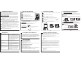
Press intheClockmodetodisplay
the minimum temperature
The MIN symbol will appear.
MIN
.
To return to normal temperature
display, press again.MIN
To return to normal temperature
display, press again.MAX
Press inClockmodetodisplay
the maximum temperature.
The MAX symbol will appear.
MAX
NOTE: Min/Max readings are automatically cleared daily at 00:00
Press to view the minimum or maximum temperatures of the
local and remote channels 1 to 4.
CHN
1
1
LOW BATTERY INDICATION
Replace the batteries when the Low Battery Indication lights up on
the LCD screen by the local (indoor) temperature display.
NOTE: After replacing the batteries, you will need to perform the Setup
and Learn Function procedures again. Refer to the GETTING STARTED
and WIRELESS TRANSMISSION sections.
Replace the batteries when the Low Battery Indication lights up on
the bottom-left corner of the LCD screen on the WT440 transmitter.
When the batteries are low on a transmitter, a Low Battery Indication
willalsolightupontheLCDscreenoftheWS222receiverforthat
particular channel.
MINIMUM
MAXIMUM
A
B
B
C
3
4
B
*
A
*
*
2
2
3
3
4
4
1
1
2
1
2
3
*
4
TEMPERATURE ALARM
The is an ideal feature to be used for greenhouses
and wine cellars, or any place that you require controlled temperature.
Once activated, the temperature alarm would sound when the room gets
too warm or too cold depending on your settings.
temperature alarm
You can set both an upper and lower temperature alarm for the local
temperature (main receiver unit) and/or for each of the remote
(outdoor) channels of 1 to 4.
Scroll to the Upper Temperature Alarm Setting mode by pressing .
You should see the symbol and dotted lines ( ) or pre-existing
setting blink.
MODE
---
Select the desired channel, local or remote channels (1 to 4) using .CHN
Press to finish; or rMODE epeat steps for all
other channels if desired.
Press or key to set the desired value for the upper temperature limit.+-
To disable the particular alarm, press .
The dotted lines ( ) would reappear to indicate
that the alarm has been disabled.
ALARM
---
Setting the Upper Temperature Alarm
UPPER TEMPERATURE LIMIT: warmIf the temperature gets too
and reaches the upper temperature limit, the alarm would sound.
LOWER TEMPERATURE LIMIT: coldIf the temperature gets too
and reaches the lower temperature limit, the alarm would sound.
1
2
3
*
4
TEMPERATURE ALARM
Scroll to the Lower Temperature Alarm Setting mode by pressing .
You should see the symbol and dotted lines ( ) or pre-existing
setting blink.
MODE
---
Select the desired channel, local or remote channels (1 to 4) using .CHN
Press to finish; or rMODE epeat steps for all
other channels if desired.
NOTE: In the normal clock display, when either the upper or lower
temperature alarm has been set for a particular channel, the or
symbol will show up solid on the LCD screen when that channel is displayed.
Press or key to set the desired value for the lower temperature limit.+-
To disable the particular alarm, press .
The dotted lines ( ) would reappear to indicate
that the alarm has been disabled.
ALARM
---
Setting the Lower Temperature Alarm
When the Temperature Alarm Sounds
The temperature alarm will sound when the actual temperature has
reached (or exceeded) the upper or lower temperature limit.
The temperature alarm has a distinctive tone different to that of
the clock alarm.
or symbol and temperature limit will blink
Press ANY key to stop the temperature alarm. Or without interruption,
the temperature alarm will automatically stop after one minute.
C
A
1
2
3
5
4
PAGE 1
PAGE 9
PAGE 2 PAGE 3 PAGE 4
PAGE 10 PAGE 11 PAGE 12
1
3
2

Remote (Outdoor) Temperature
Local (Indoor) Temperature
Selecting C or F Temperature Display°°
TEMPERATURE DISPLAY
If the Learn Function is performed successfully (refer to the WIRELESS
TRANSMISSION section), the remote (outdoor) temperatures will display in
the bottom-right corner of the LCD screen.
Press to toggle between channels 1, 2, 3 and 4.CHN
The local (indoor) temperature is displayed in two locations.
GRAPHICAL - the local (indoor) temperature is shown as a bar graph on
the left of the LCD screen.
NUMERICAL - the local (indoor) temperature can be viewed at the
bottom-right of the LCD screen.
NOTE:
CHN
The remote (outdoor) temperatures are also shown here. You can
scroll through the local and remote channels 1 to 4 by pressing .
Toggle between C and F by pressing in the Clock mode.°° °C/°F
1
A
2
B
C
WIRELESS TRANSMISSION
For optimal performance:
1
1
2
2
3
3
4
4
6
Place the receiver and remote transmitter side by side about 1 metre
apart, and allow the receiver and remote transmitter to synchronize
for 10 minutes before you place the remote transmitter outdoors.
Environmental factors and signals from other household devices, such
as remote entry controls, security systems, and computers, may
interfere with the wireless transmission of this product and cause
temporary reception loss. This is normal and does not affect the general
performance of this product. Stable reception will resume once the
interference ends.
The remote transmitter should be placed in a dry shaded area.
NOTE: Fog and mist will not harm the remote transmitter but
direct rain must be avoided.
Mount the remote transmitter upright avoiding metallic objects
and frames, such as window sills. Verify that there are no obstacles
like a transmission tower or steep hill that can cause interference
and blockage between the remote transmitter and receiver.
Place the receiver unit at least 2 metres away from any electrical
devices, such as your television set, computer, cordless phone, or
any radio controlled equipment.
Replace unit(s) with fresh batteries when the Low Battery Indicator
lights up. Refer to the LOW BATTERY INDICATION section.
You may need to reposition the remote transmitter to a different
location and/or closer to the receiver for the best transmission.
SPECIFICATIONS
WS222 - WEATHER STATION RECEIVER
- Battery Type: 2 X 1.5V AA batteries
- Operating Temperature:
- Temperature Range:
-
-5°C to 50°C
-20°C to 55°C
1°C 0°C to 40°C
1°C
- Measurement Accuracy: Max. +/- within measuring range of
Resolution: 0.
WT440 - WEATHER STATION TRANSMITTER
- Battery Type: 2 X 1.5V AA batteries
- -20°C to 60°C
Temperature Range: -30°C to 70°C
0.1°C -10°C 1°C -10°C
1°C 0°C to 40°C
Operating Temperature:
-
- Temperature Resolution: for above / for below
- Measurement Accuracy: Max. +/- within measuring range of
- Transmission Frequency: 433.92 MHz
- Transmission Range: up to 40 metres in open area
THIS DEVICE COMPLIES WITH PART 15 OF THE FCC RULES.
OPERATION IS SUBJECT TO THE FOLLOWING TWO CONDITIONS:
1. THIS DEVICE MAY NOT CAUSE HARMFUL INTERFERENCE, AND
2. THIS DEVICE MUST ACCEPT ANY INTERFERENCE RECEIVED,
INCLUDING INTERFERENCE THAT MAY CAUSE UNDESIRED OPERATION.
FCC COMPLIANCE
TROUBLESHOOTING
CLOCK SETTING
DAY/NIGHT ICON
ALARM SETTING
Press and hold for 3 seconds to enter the Clock Setting mode.
You will hear a beep and the time will blink.
MODE
The day/night icon will change automatically depending on the time of day.
Scroll to the Alarm mode using . The symbol will appear.MODE AL
Press to set the hour.HOUR
DAY ICON:
The day icon is represented by a blinking sun, and a cloud.
- The day icon will be displayed between 6:00am to 5:59pm.
NIGHT ICON:
The night icon is represented by a half-cresent moon with stars and a cloud.
- The night icon will be displayed between 6:00pm to 5:59am.
Press to set the hour.HOUR
Press during clock setting to
change between 12 and 24 hour display.
ALARM/(°C/°F)
Press to toggle alarm on and off.ALARM
In the normal clock display, if the alarm is set ON, the symbol
will also appear on the display.
Press or no key press for one minute
will end clock setting.
MODE
When the alarm is set ON, the symbol will appear and the unit
will beep.
LIMITED TWO-YEAR WARRANTY
UPM warrants this product, excluding battery, to be free from defects in the materials or workmanship, under normal
use and service, for a period of two years from the date of purchase by the consumer.
If, at any time during the warranty period, the product is defective or malfunctions, UPM shall repair or replace it (at
UPM's discretion) within a reasonable period of time.
If the product is defective,
(i) return it, with a dated proof of purchase, to the retailer from which you purchased it, or
(ii) package it carefully, along with a dated proof of purchase and a short description of the malfunction, and mail it,
postage prepaid, to the following address:
UPM Marketing Inc.
Return Goods
Unit 10B - 250 Shields Court
Markham, Ontario
L3R 9W7
This warranty does not cover removal or reinstallation costs. This warranty shall not apply if it is shown by UPM that
the defect or malfunction was caused by damage which occurred while the product was in the possession of the
consumer.
UPM's sole responsibility shall be to repair or replace the product within the terms stated above. UPM SHALL NOT BE
LIABLE FOR ANY LOSS OR DAMAGE OF ANY KIND, INCLUDING ANY INCIDENTAL OR CONSEQUENTIAL DAMAGES
RESULTING, DIRECTLY OR INDIRECTLY, FROM ANY BREACH OF ANY WARRANTY, EXPRESS OR IMPLIED, OR ANY
OTHER FAILURE OF THIS PRODUCT. Some states do not allow the exclusion or limitation of incidental or
consequential damages, so this limitation may not apply to you.
THIS WARRANTY IS THE ONLY EXPRESS WARRANTY UPM MAKES ON THIS PRODUCT. THE DURATION OF ANY
IMPLIED WARRANTIES, INCLUDING THE WARRANTIES OF MERCHANTABILITY AND FITNESS FOR A PARTICULAR
PURPOSE, IS HEREBY LIMITED TO THE TWO YEAR DURATION OF THIS WARRANTY. Some states do not allow
limitations on how long an implied warranty lasts, so the above limitation may not apply to you.
This warranty gives you specific legal rights, and you may have other rights which may vary from state to state.
If you have any questions concerning this warranty, please write to:
UPM Marketing Inc.
Customer Service Department
Unit 10B - 250 Shields Court
Markham, Ontario
L3R 9W7
Or call 1-888-GO-TO-UPM (1-888-468-6876), Monday to Friday, from 9:00am to 5:00pm eastern.
(2)
The remote (outdoor) readout on the receiver is
blinking.
The remote (outdoor) readout on the receiver is
blinking. The receiver will not detect or receive
the temperature data from the remote transmitter,
even after the Manual Learn Function has been
executed.
The temperature data on the remote transmitter
does not match the data displayed on the
receiver.
The temperature data on the remote transmitter
does not match the data displayed on the
receiver.
This may also be the result of a temporary loss of reception due
to interfering sources. Normal reception should resume once
the interference ends. Refer to the WIRELESS TRANSMISSION
section.
Re-synchronize the remote transmitter and receiver by pressing
and holding on the receiver for 3 seconds until a beep is
heard. The temperature data from the remote transmitter will
display on the receiver within 3 minutes. Refer to the WIRELESS
TRANSMISSION (Manual Learn Function) section.
CHN
Ensure the remote transmitter is away from any possible source of
interference and electrical disturbances. You may try to reposition
the remote transmitter in a different location and/or closer to the
receiver. The remote transmitter does have a maximum range of
40 metres, but any walls or windows the signal has to pass through
will reduce the distance. Due to the nature of the batteries,
extreme cold temperatures may also affect the transmission range.
Refer to the WIRELESS TRANSMISSION section and repeat the
Manual Learn Function with the remote transmitter in a new
location.
This may occur when you move the remote transmitter from one
environment to another. For example, when you bring the
transmitter from inside the warm house out to the cold exterior. In
such a case, there will be a big change in temperature. The
transmitter will record this change in temperature much quicker
than it is able to transmit the data to the receiver (which is done
once every minute). Therefore, you will temporarily get a
difference in reading between the remote transmitter and receiver.
The solution is to allow the remote transmitter some time to sit in
its new location to reach equilibrium. This may take several
minutes. Once the data is stable, the data displayed on the
remote transmitter should match that displayed on the receiver.
PROBLEM
SOLUTION
CUSTOMER SUPPORT HOTLINE: 1-888-468-6876
2
A
1
2
3
4
5
1
5
2
3
4
Press to set the minute.MIN
Press to set the minute.MIN
5
5
Alarm Setting
Clock Display
6
Local (Indoor) Temperature Remote (Outdoor) Temperature
Remote (Outdoor) Temperature
EXAMPLE:
EXAMPLE:
1
C
B
Remote
Channel
Number
Remote
Channel
Number
PAGE 5 PAGE 6 PAGE 7 PAGE 8
PAGE 13 PAGE 14 PAGE 15
Page is loading ...
Page is loading ...
-
 1
1
-
 2
2
-
 3
3
-
 4
4


UPM WS222 - WT440 Owner's manual
- Type
- Owner's manual
Ask a question and I''ll find the answer in the document
Finding information in a document is now easier with AI
in other languages
Related papers
Other documents
-
Voxx Accessories RCWS50A User guide
-
RCA RCWS50 User guide
-
 La Crosse Technology WS7034UITCA User manual
-
 La Crosse Technology WS9029UITCA User manual
-
iLuv Morning Call 5 Qi User manual
-
 La Crosse Technology WS-7013U User manual
-
National Geographic VA colour RC Weather Station Owner's manual
-
TFA Wireless Weather Station with 3D Display CRYSTAL CUBE Owner's manual
-
 La Crosse Technology WS-1610TWC-IT User manual
-
Irox HBR425I Owner's manual


