Page is loading ...

E-Stop Safety Modules with Adjustable Delay
®
Models ES-TN-14H5 with 0-20 second delay, ES-TN-14H6 with 0-200 second delay
Features
• Selectable Auto-Reset or monitored Manual Reset.
• Auto or manual power-up
• One- or two-channel feedback monitoring
• Monitors one dual-channel or one single-channel normally closed E-stop switch
circuit for a contact failure or wiring fault (safety category 2 or 4,
per ISO13849-1 [EN954-1]; see pages 5-7).
• 4 amp safety output contacts
• Removable terminal blocks
• Input monitoring circuit has diverse-redundant microprocessors
• Designed for use in functional stop Category 0 and 1 applications (per ISO/EN
60204-1 and NFPA79)
• Four immediate output switching channels (functional stop Category 0) and four
delayed output switching channels (functional stop Category 1). Delay time is
adjustable from 0-20 seconds or 0-200 seconds, depending on model.
• One auxiliary non-safety, normally closed immediate output and one auxiliary
non-safety normally closed delayed output for status monitoring.
WARNING . . .
This Emergency Stop
Safety Module is not
a point-of-operation
guarding device, as
defined by OSHA regulations. It
is necessary to install point-of-
operation guarding devices, such
as safety light screens and/or hard
guards, to protect personnel from
hazardous machinery. Failure to
install point-of-operation guards
on hazardous machinery can
result in a dangerous condition
which could lead to serious
injury or death.
!
Buy: www.ValinOnline.com | Phone 844-385-3099 | Email: [email protected]

E-Stop Safety Modules with Adjustable Delay – Models ES-TN-14H5/-14H6
!
Important ... read this page before proceeding!
Banner Engineering Corp. has made every effort to provide complete application, installation, operation, and maintenance
instructions. In addition, any questions regarding the use or installation of this Banner Emergency Stop Safety Module should
be directed to the factory applications department at the telephone numbers or address shown on back cover.
The user shall ensure that all machine operators, maintenance personnel, electricians, and supervisors are thoroughly familiar
with and understand all instructions regarding the installation, maintenance, and use of this Emergency Stop Safety Module,
and with the machinery it controls.
The user and any personnel involved with the installation and use of this model Emergency Stop Safety Module must
be thoroughly familiar with all applicable ANSI/NFPA standards. The standards, listed below, directly address the use
of emergency stop systems. Banner Engineering Corp. makes no claim regarding a specific recommendation of any
organization, the accuracy or effectiveness of any information provided, or the appropriateness of the provided information
for a specific application.
The user has the responsibility to ensure that all local, state, and national laws, rules, codes, and regulations relating to the
use of this Emergency Stop Safety Module in any particular application are satisfied. Extreme care is urged that all legal
requirements have been met and that all installation and maintenance instructions contained in this manual are followed.
U. S. Standards Applicable to Use of Emergency Stop Safety Modules
ANSI B11 Standards for Machine Tools “Safety Requirements for the Construction, Care and Use”
Avail
able from: Safety Director
AMT –
The Association for Manufacturing Technology
7901
Westpark Drive
McLea
n, VA 22101-4269
Tel.:
703-893-2900
NFPA79 “Elec
trical Standard for Industrial Machinery (1997)”
Avail
able from: National Fire Protection Association
1 Bat
terymarch Park, P.O. Box 9101
Quinc
y, MA 02269-9101
Tel.:
800-344-3555
ANSI/RIA R15.06 “Safety Requirements for Industrial Robots and Robot Systems”
Avail
able from: Robotic Industries Association
900 V
ictors Way, P.O. Box 3724
Ann A
rbor, MI 48106
Tel.:
734-994-6088
European Standards Applicable to Use of Emergency Stop Safety Modules
ISO/TR 12100-1 & -2 (EN292-1 & -2) “Safety of Machinery – Basic Concepts, General Principles for Design
Part
1: Basic Terminology, Methodology, and
Part
2: Technical Principals and Specifications”
ISO 13849-1 (EN954-1) “Safe
ty of Machines: Safety Related Parts of Control Systems”
IEC/EN60204-1 “Elec
trical Equipment of Machines: Part 1: General Requirements”
Also,
request a type “C” standard for your specific machinery.
ISO 13850 (EN418) “Safe
ty of Machinery – Emergency Stop Equipment Functional Aspects, Principles for Design”
Avail
able from: Global Engineering Documents
15 In
verness Way East
Engle
wood, CO 80112-5704
Tel.:
800-854-7179
Buy: www.ValinOnline.com | Phone 844-385-3099 | Email: [email protected]

E-Stop Safety Modules with Adjustable Delay – Models ES-TN-14H5/-14H6
Overview
The purpose of an Emergency Stop Safety Module (E-Stop Safety Module) is to
increase the control reliability of an emergency stop circuit. As indicated in Figures 2
and 3, the E-Stop Safety Modules described in this document are designed to monitor
a 1-channel or 2-channel E-stop switch. A 2-channel E-stop switch has two electrically
isolated contacts.
ISO 13849-1 Safety Categories
Both contacts of a 2-channel E-stop switch are monitored by the Safety Module. If
either input is short-circuited, the Safety Module cannot be reset, and the controlled
machinery cannot be restarted, following actuation of the E-stop switch. Two-channel
E-stop switches used with this Safety Module are suitable for Safety Category 4
applications, per European Standard ISO 13849-1 (EN954-1), of which Category 4 is
the highest safety category.
Use of a 1-channel E-stop switch provides no input redundancy, and no ability for the
Safety Module to monitor for input short circuits. One-channel E-stop switches used
with this Safety Module are generally suitable only for Safety Category 2 applications,
per ISO 13849-1 (EN954-1).
IEC/EN60204-1 and NFPA79 Functional Stop Categories
In a functional Category 0 emergency stop circuit, the opening of either of the two
E-stop switch contacts (or the one contact, if configured to 1-channel) immediately
removes electrical power from the machine control elements, which react to stop
hazardous machine motion and/or other machine hazards. This redundancy of
stopping control offered by a two-pole E-stop switch is the first step towards control
reliability in an emergency stop circuit.
A functional stop Category 1 emergency stop circuit is a controlled stop with power
available to the machine actuators to achieve the stop and then removal of power when
the stop is achieved. When a Category 1 stop function is used, final removal of power
must be ensured by means of electromechanical switching devices.
Functional stop Category 1 stops are intended for use on machines where immediate
removal of power would not stop the machine immediately because its high speed,
high mass or momentum would cause the machine to run on. To stop such machines
quickly and safely, electro-mechanical or electrical brake systems like DC-injection
brakes or reverse current via the machine’s actuators are commonly used.
The outputs of E-stop Safety Modules ES-TN-1H5 and -1H6 are two redundant
normally open immediate safety contacts (each of which is a series of two forced-
guided relay contacts, K1 and K2 in Figure 3), and two redundant normally open
delayed contacts (also each a series of two forced-guided relay contacts, K3 and K4).
The delayed contacts may be used in a functional stop Category 1 application.
Key to Categories
• A Functional Stop Category (0, 1 or
2), per EN60204-1 and NFPA79, refers
to the type of stopping action required
by the guarded machine in question.
Some machines may be stopped safely,
immediately following a stop command
(removal of power); others, due to their
high speed, mass or momentum, would
run on following an immediate stop
command. These machines require power
to be provided to the guarded machine’s
braking system for a specified delay time,
to effect a controlled stop.
Category 0 Stop: immediate removal of
power, uncontrolled stop
Category 1 Stop: controlled stop with
a delay before power is removed from
guarded machine
Category 2 Stop: controlled stop with
power left available to the guarded machine
actuators
• A Safety Category (B, 1, 2, 3 or 4), per
EN954-1, refers to “the performance of
a safety related part of a control system
(or circuit) with respect to the occurrence
of faults...” Of the many factors involved
when selecting an appropriate safety
category, hazard analysis, risk assessment
and risk reduction are among the most
important. The level of risk is based on
the severity of a potential harm and its
probability of occurring, which is used to
determine the appropriate performance of
a control system or circuit. Typically, as
described in Annex B of EN954-1, in cases
where serious injury is possible:
- Safety Category 2 would be selected
only if exposure to a hazard is
infrequent, and of a short duration.
- Safety Category 4 would be selected
if exposure to a hazard is frequent to
continuous, or if exposure is for a long
duration.
For more information, refer to standards
EN954-1, EN418, NFPA 79, EN60204-1 and
British Standard 5304:(1988).
Buy: www.ValinOnline.com | Phone 844-385-3099 | Email: [email protected]

E-Stop Safety Modules with Adjustable Delay – Models ES-TN-14H5/-14H6
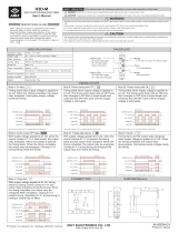
Figure 1. ES-TN-14H5 and -14H6 status
indicators and terminal locations
In addition to the safety contacts, the E-Stop Safety Module has one normally closed
immediate auxiliary contact (from K1 and K2) and one normally closed delayed
auxiliary contact (from K3 and K4) for status monitoring by a process controller.
All output contacts of the E-Stop Safety Module, the normally open and the normally
closed, are rated for up to 250V ac/dc at up to 4 amps.
The E-Stop Safety Module also provides a necessary reset function. ANSI B11 and
NFPA 79 standards require that a Reset routine be performed after returning the E-stop
switch to its closed-contact position. This prevents the controlled machinery from
restarting simply by closing the E-stop switch. Models ES-TN-14H5 and -14H6 may
be configured for Automatic Reset via two DIP switches located inside the Module
housing, under the front cover (see Figures 5 and 6). Automatic Reset mode is
useful for some automated processes. However, when Automatic Reset is used,
an alternate means must be established to require a Reset routine after the E-stop
switch is returned to its closed-contact position (see WARNING on page 9).
This E-Stop Safety Module complies with the following design standards:
ISO 13850 Emergency Stop Equipment – Functional Aspects,
Principles for Design
ISO 13849-1 Safety of Machinery: Safety-related Parts of Control Systems
Part 1: General Design Directives (Safety Category 4)
ISO 12100-2 Safety of Machinery: Basic Concepts, General Principles for Design
(EN292-2) Part 2: Technical Principles and Specifications
IEC 60204-1 Safety of Machinery: Electrical Equipment of Machines
Part 1: General Requirements
The Safety Module has indicators for input power (Power), internal faults (Fault), E-
stop inputs (E-Stop), reset input (Reset), monitoring of feedback contacts (Monitor),
immediate outputs (Out) and delayed outputs (Timed-Out); see Figure 1.
E-Stop Safety Modules ES-TN-14H5 and -14H6 have no user-serviceable parts. See
page 16 for information regarding repair service.
Buy: www.ValinOnline.com | Phone 844-385-3099 | Email: [email protected]

E-Stop Safety Modules with Adjustable Delay – Models ES-TN-14H5/-14H6
E-Stop Switch Requirements
As shown in Figure 3, the E-stop switch must provide one or two contacts which are
closed when the switch is armed. Once activated, the E-stop switch must open all
its contacts, and must be returned to the closed contact position only by means of
a deliberate action (such as twisting, pulling, or unlocking). The switch should be a
“positive-opening type,” as described by IEC 60947-5-1. A mechanical force applied
to such a button (or switch) is transmitted directly to the contacts, forcing them open.
This ensures that the switch contacts will open whenever the switch is activated. NFPA
79 section 13.2, Emergency Stop Devices, specifies the following additional switch
(“stop control”) requirements:
• Emergency Stop push buttons shall be located at each operator control station and
at other operating stations where emergency shutdown shall be required.
• Stop and Emergency Stop push buttons shall be continuously operable from all
control and operating stations where located.
• Actuators of Emergency Stop devices shall be colored RED. The background
immediately around the device actuator shall be colored YELLOW. The actuator of a
push-button-operated device shall be of the palm or mushroom-head type.
• The Emergency Stop actuator shall be a self-latching type.
NOTE: Some applications may have additional requirements. The user must refer to all
relevant regulations.
If the Module is configured for 1-channel E-stop (S11-S12), a jumper must be installed
on the second channel (S21-S22) and configured for 1-channel input; see Figure 6.
When a 1-channel E-stop is used, the user must guard against failure modes that can
result in an unsafe condition, for example the failure of the contact to a short circuit
condition. A switch with positive opening operation should be used to reduce the
possibility of a failure of the switch to open. A short circuit failure results in loss of
switching function. This can occur from a short across the switch contacts, a short
across the wires connected to the switch somewhere between the switch and the
E-Stop Safety Module, or a short to a secondary source of power. To reduce these
possibilities, physically separate the wires from each other and from other sources of
power (e.g., in separate wireways or conduit).
According to the definition of European standard ISO 13849-1 (EN954-1), a 1-channel
E-stop generally should be used only in an application where Safety Category 2 or less
(1 or B) has been determined via a risk-assessment procedure.
Two-channel E-stops, with positive open switches, are designed to issue a stop
command even in the event of a single failure of this type and provide a high level of
safety.
If the Module is configured for 2-channel E-stop, the immediate normally open output
contacts (13-14, 23-24, 33-34 and 43-44), will open and the normally closed auxiliary
contact (91-92) will close as soon as at least one of the two E-stop contacts opens.
The second contact, however, must open within 2 seconds of the first one; if not, the
unit will go into a lockout condition that results in the outputs opening and requiring a
reset after the fault has been corrected.
WARNING . . .
1-Channel Input
If a 1-channel E-stop button
is used, a single fault (such as a short
across the single E-stop contact or from
the contact to a secondary source of
power) can lead to the complete loss of
safety.
A 1-channel E-stop should be used
only in applications where such a fault
can be excluded, or the resulting loss
of safety cannot result in serious injury
or death (Safety Category 2, 1 or B;
see page 3).
If a 1-channel E-stop is used, separate
the wires from each other by routing
them through separate wireways
or conduit in order to increase the
reliability of the interface.
!
Buy: www.ValinOnline.com | Phone 844-385-3099 | Email: [email protected]

E-Stop Safety Modules with Adjustable Delay – Models ES-TN-14H5/-14H6
S12
S22
S11
S21
Figure 2. Series connection of multiple
E-Stop switches. Jumper between
S21 and S22, if 1-channel E-stop
is selected.
Mechanical Installation
The E-Stop Safety Module must be installed inside an enclosure. It is not designed for
exposed wiring. It is the user’s responsibility to house the E-Stop Safety Module in an
enclosure with NEMA 3 or IEC IP54 rating, or better.
Dimensions of the Safety Module are shown in Figure 8, page 16. The Safety Module
mounts directly to standard 35 mm DIN rail.
Heat Dissipation Considerations
For reliable operation, the user must ensure that the operating specifications are not
exceeded. The enclosure must provide adequate heat dissipation, so that the air closely
surrounding the Module does not exceed the maximum operating temperature stated
in the specifications (page 15). Methods to reduce heat build-up include venting,
forced airflow (e.g., exhaust fans), adequate enclosure exterior surface area and
spacing between modules and other sources of heat.
Electrical Installation
It is not possible to give exact wiring instructions for a device such as an E-stop
Safety Module which interfaces to a multitude of machine control configurations. The
following guidelines are general in nature.
Models ES-TN-14H5 and -14H6 have four redundant immediate normally open supply
output contacts (13-14, 23-24, 33-34 and 43-44), as well as four redundant delayed
contacts (57-58, 67-68, 77-78 and 87-88). This qualifies this E-Stop Module to be
used in applications as a functional stop Category 0 or 1 E-Stop Control as defined by
NFPA 79 and ISO 13850 (EN418).
NOTE: As the normally open immediate and delayed output contacts come from
physically separate relays, a fault could cause only one set of contacts (either the
immediate or the delayed) to close after a manual or auto reset. This possibility
must be considered in the design of the machine control circuit.
Connection of E-Stop Switch
Connect the poles of the E-Stop switch as shown in Figure 3. The switch in Figure 3
is shown in the “armed” position with both contacts closed. Multiple E-stop switches
connected to one E-stop Safety Module must be series connected (see Figure 2 and
the warning at right).
CAUTION. . .
Shock Hazard
Always disconnect power
from the E-stop Safety
Module and all power from the machine
being controlled before making any
wire connections.
Electrical installation and wiring must be
made by qualified personnel and must
comply with the NEC (National Electrical
Code), EN60204-1 and -2, and all
applicable local standards and codes.
WARNING . . .
Multiple E-Stop Switches
Whenever two or more E-stop switches
are connected to the same E-Stop Safety
Module:
• The contacts of both switches must
be connected together in series. This
series combination is then wired to the
respective Safety Module input. Never
connect the contacts of multiple E-
stop switches in parallel to the E-Stop
Safety Module inputs; this defeats the
switch contact monitoring ability of the
Safety Module, and creates an unsafe
condition.
• Each switch must be individually
actuated (engaged), then re-armed
and the E-Stop Safety Module reset (if
Manual Reset mode is selected). This
allows the monitoring circuits to check
each switch and its wiring to detect
faults.
Failure to do so could result in
undetected faults and create an unsafe
condition which could result in serious
injury or death.
!
Buy: www.ValinOnline.com | Phone 844-385-3099 | Email: [email protected]

E-Stop Safety Modules with Adjustable Delay – Models ES-TN-14H5/-14H6
24V dc
Reset
Switch**
(jumper for Auto Reset -
see Warning on page 9)*
MSC-Monitor Contacts
(jumper if no feedback
contacts are monitored)*
MSC-Monitor Contacts
(jumper if 1 channel feedback
is selected or no feedback)*
Emergency Stop Switch
Cancel Delay Input
*(Jumper on
S21-S22
for 1-channel
E-Stop)
(See WARNING)
L2
A2
MSC1
MSC2
Machine Master
Stop Control
Elements
Immediate
Immediate
Immediate
Delayed
Delayed
Delayed
Non-safety Auxiliary
Monitor Contacts
K1
A
4A max.
4A max.
4A max.
K2
A
K1
B
K2
B
K3
A
K4
A
MSC3
A1
4A max.
K3
B
K1
E
K2
E
MSC1
MSC3
MSC2
MSC4
K4
E
K3
E
K4
B
MSC4
91 92
S21
S11
Y1
S12
S22
L1
dc common
+V
ES-TN-14H5
ES-TN-14H6
Y2
MSC1 MSC3
S33
X1
X2
01 02
X3
X4
X5
X6
***
***
***
***
14
13
23 24
Immediate
4A max.
K1
C
K2
C
33 34
Immediate
4A max.
K1
D
K2
D
43
44
Delayed
4A max.
K3
C
K4
C
78
Delayed
4A max.
K3
D
K4
D
88
57
67
77
87
58
68
Machine
Control
Circuits
WARNING . . .
Wiring of Arc Suppressors
If arc suppressors are
used, they MUST be installed as
shown across the actuator coil of
the Master Stop Control elements
(MSC1 to MSC4). NEVER install
suppressors directly across the
output contacts of the E-Stop
Safety Module. It is possible for
suppressors to fail as a short circuit.
If installed directly across the output
contacts of the Safety Module, a
short-circuited suppressor will
create an unsafe condition which
could result in serious injury or
death.
!
Figure 3. E-Stop Safety Modules ES-TN-14H5 and -14H6 hookups
* See page 11 for DIP-switch configuration.
** The Safety Module can not be reset until the delay output
times out and switches, or until the Cancel Delay Input is
exercised. Attempting to reset the module (Manual Reset
mode) or re-arming the E-stop button (Auto Reset mode)
before the time-out occurs will result in a lockout (see
page 14 for instructions for clearing lockouts).
*** Arc suppressors (see WARNING).
WARNING . . .
Interfacing MSCs
NEVER wire an
intermediate device (e.g., PLC, PES,
PC) between E-Stop Safety Module
outputs and the Master Stop Control
Element it switches, in such a manner
that:
• In the event of a failure there is a loss
of the safety stop command, or,
• The safety function can be
suspended, overridden, or defeated,
unless accomplished with the same
or greater degree of safety.
Whenever forced-guided, mechanically
linked relays are added as intermediate
switching devices, a normally closed
forced-guided monitor contact from
each relay must be added to the
series feedback loop between Safety
Module terminals X3 and X4 or X5
and X6.
!
Buy: www.ValinOnline.com | Phone 844-385-3099 | Email: [email protected]

E-Stop Safety Modules with Adjustable Delay – Models ES-TN-14H5/-14H6
Connection of Safety Switches
Models ES-TN-14H5 and ES-TN-14H6 may be used as a safety gate monitoring module.
To achieve Safety Category 4 operation per ISO 13849-1, two individually mounted,
positive-opening safety switches that operate concurrently when the gate or guard is
opened must be used (see Figure 4).
The ES-TN-14H5 and ES-TN-14H6 verify concurrent opening of two contacts – one from
each safety switch. Reset of the Safety Module is not possible if one switch fails to open,
or if a short circuit occurs between the safety switches or to dc common or to +24V.
Please contact the Banner Factory Applications Group at the numbers listed on the last
page to discuss your intended use.
Connection of Reset Switch (Manual Monitored Reset)
The Reset Circuit switch can be any mechanical switch, such as a normally open
momentary switch, or a two-position key switch. The Reset switch must be capable
of reliably switching 18-30V dc at 10-25 mA. As shown in Figure 2, the Reset switch
connects between terminals X1 and X2 of the Safety Module. A reset will occur after
the Reset button goes from open, to closed, and back to open state.
The Reset switch must be located outside of – and not be accessible from – the
area of dangerous motion, and must be positioned so that any area of dangerous
motion may be observed by the switch operator during the Reset procedure.
External Device Monitoring (EDM)
To satisfy the requirements of Safety Category 4 of ISO 13849-1, the Master Stop
Control (MSC) elements must each offer a normally closed, forced-guided monitor
contact. For 2-channel monitoring, one normally closed monitor contact from one
MSC element, controlled by one of the immediate output contacts from the Module,
is wired in series to one normally closed monitor contact from one MSC element,
controlled by one of the delayed output contacts from the Module, to input X3-X4. The
same configuration (one immediate N.C. series connected to one delayed N.C.) is wired
to X5-X6 (Figure 2). In operation, if one of the switching contacts of any MSC element
fails in the shorted condition, the associated monitor contact will remain open, making
reset of the Module impossible.
There is no specific feedback input to which the immediate MSCs must be connected.
However, two immediate contacts (from two MSCs) or two delayed contacts (from
two MSCs) should not be connected to the same input. If 1-Channel Monitoring
is selected, input X5-X6 must be jumpered, the Module configured for 1-Channel
Monitoring (see Figure 2) and all monitoring contacts must be wired in series to X3
and X4. See 1-Channel, 2-Channel, or No External Device Monitoring on page 10 for
more information.
Connection to the Guarded Machine
The hookup diagram (Figure 2) shows a generic connection of 4 of the E-Stop Safety
Module’s eight redundant output circuits to Master Stop Control elements MSC1 through
MSC4. A Master Stop Control element is defined as an electrically powered device,
external to the E-Stop Safety Module, which stops the machinery being controlled by
immediately removing electrical power to the machine and (when necessary) by applying
braking to dangerous motion. This stopping action is accomplished by removing power
to the actuator coil of any Master Stop Control Element.
Safety Interlock
Switch #2
Safety Interlock
Switch #1
Safety
gate
or
guard
S12
S22
S11
S21
Figure 4. Hookup using contacts from
two safety switches
Buy: www.ValinOnline.com | Phone 844-385-3099 | Email: [email protected]

E-Stop Safety Modules with Adjustable Delay – Models ES-TN-14H5/-14H6
WARNING . . .
Reset
Routine Required
ANSI B11 and NFPA 79
standards require that a reset routine
be performed after returning the E-stop
switch to its closed-contact position
(arming the E-stop switch). When
Automatic Reset is used, an alternate
means must be established to require a
reset routine, after the E-stop switch is
armed. Allowing the machine to restart
as soon as the E-stop switch is armed
creates an unsafe condition which could
result in serious injury or death.
!
WARNING . . .
Auto Power-Up and
Momentary Power Loss
If Auto Power-Up is selected, a
momentary loss of power could cause
the outputs to energize, even without a
manual reset, when the power resumes.
Be sure that this Auto Power-Up situation
does not cause the machine to restart, or
an unsafe condition may occur that could
result in serious injury or death.
!
Configuration
Automatic Reset Mode
The E-Stop Safety Module may be configured for Automatic Reset via two independent
DIP switches, located inside the Module housing, under the front cover (see Figures 5
and 6) and by replacing the Reset switch with a jumper wire in the X1-X2 reset input
circuit (see Figure 2).
The E-Stop Safety Module will reset (and the outputs energize) as soon as the E-Stop
switch returns to its closed-contact position (S11-S12 and S21-S22 closed), feedback
inputs are closed (X3-X4 and X5-X6), and no fault exists. Automatic Reset will not
occur if Manual Power-up is selected and the E-stop switch is already closed when
power is applied.
Automatic reset mode is useful for some automated processes. However, if Automatic
Reset is used, it is necessary to provide a means of preventing resumption of
hazardous machine motion, until an alternate reset procedure is performed. The
alternate procedure must include a Reset switch, located outside the area of dangerous
motion, which is positioned so that any area of dangerous motion may be observed by
the switch operator during the reset procedure.
NOTE: The minimum amount of time required for the Module to be in a STOP or
OFF condition is 100 ms. This “recovery time” (OFF-state) is required for the
internal circuitry of the Safety Module to normalize, allowing a reliable reset
to occur. A lockout will occur if the Module is cycled too quickly. To clear
the lockout, the Module must be re-cycled, meeting the minimum OFF time
requirement.
Auto Power-Up
If the Module is programmed for Auto Power-Up (see Figures 6 and 7), K1-K4 relays
will close as soon as power is connected to A1-A2 – if the E-stop inputs S11-S12 and
S21-S22 are closed, the appropriate jumpers are installed and feedback contacts X3-X4
and X5-X6 are closed, whether the Module is programmed for Auto or Manual Reset.
Auto Reset may be used only if the machine being controlled will not initiate dangerous
motion if power is applied to or interrupted from the module. In addition, an alternate
Reset routine must be required (see WARNING at left).
The next time the E-stop is cycled when the Module is set to Manual Reset, the Reset
button at X1-X2 must go from open to closed and back to open in order to reset the
unit and energize the four internal relays.
NOTE: Auto Power-Up in combination with Manual Reset energizes the output contacts
automatically only one time after applying power to the Module. Cycling the
E-stop button while power is applied will not reset the unit.
Manual Power-Up
If the DIP switches are set to Manual Power-Up and Manual Reset, the unit will reset
only after power is applied and the Reset button is pushed and released. If Manual
Power-Up and Auto Reset is selected, the E-stop button must be cycled (opened and
closed) if it is closed after power up (but simply closed if it is open after power-up).
Buy: www.ValinOnline.com | Phone 844-385-3099 | Email: [email protected]

E-Stop Safety Modules with Adjustable Delay – Models ES-TN-14H5/-14H6
Cancel Delay Input
The Cancel Delay Time input Y1-Y2 must be open during normal operation. After
the E-stop button is activated (its contacts opened), and the delay time is running, a
momentary closing of input Y1-Y2 will immediately terminate the delay time and open
contacts 57-58, 67-68, 77-78 and 87-88, and close contact 01-02. A jumper between
Y1-Y2 results in a Fault condition.
External Device Monitoring Settings
1-Channel Monitoring
If 1-channel monitoring is selected (see Figure 6), one or more normally closed
contacts from the MSCs must be wired to terminals X3-X4. If more than one contact is
used, they must be wired in series (see Figure 3). The second channel (X5-X6) must be
jumpered. The Module will reset only if both inputs are closed. After the unit is reset,
the state of the X3-X4 input is irrelevant.
2-Channel Monitoring
If 2-channel monitoring is selected (see Figure 6), the Module will check both inputs
X3-X4 and X5-X6 for closed state, before a reset can occur. After the unit is reset, and
during RUN mode, both inputs will be checked for matching state. In other words, if
one input opens, the other input must open within 200 milliseconds.
If both pairs of output contacts (both immediate and delayed) are used, and MSCs from
all four contacts are controlled (Figure 3), both an immediate MSC and a delayed MSC
contact must be connected in series to each of the two feedback inputs.
No External Device Monitoring
If monitoring contacts are not required or if External Device Monitoring is not otherwise
possible, jumper both X3-X4 and X5-X6 inputs and select 2-channel monitoring. It is
the responsibility of the user to ensure that any single failure will not result in a
hazardous condition and will prevent a successive machine cycle.
CAUTION . . .
Turn OFF Power Before
Removing Cover
The front cover should only
be removed and the switches set when
no voltage is applied to terminals A1-A2.
Changing the position of the switches
while power is ON could result in a
Fault condition or a short circuit.
!
Buy: www.ValinOnline.com | Phone 844-385-3099 | Email: [email protected]

E-Stop Safety Modules with Adjustable Delay – Models ES-TN-14H5/-14H6
DIP-Switch and Selector Switch Settings
The DIP switches and selector switches are located inside the Module housing, behind
the front plate. Before adjusting any settings, turn OFF power to the Module. Remove
the front plate by using a screwdriver in the slot on the right side and gently prying the
cover away from the housing (Figure 5). Turn the rotary Delay Time selector switches
to the desired position using the same small screwdriver in the slot on the arrow. Use
the screwdriver blade to slide the DIP switches to their proper positions also.
The corresponding pairs of DIP switches and the two rotary Delay Time selector
switches must match at all times, or a Fault condition will result. (If this occurs, turn
the power OFF, adjust the pairs of switches to match, and turn the power supply back
ON.) Figure 6 shows the DIP switches and Delay Time selector switches properly set
for No Delay, Manual Reset, 1-Channel Monitoring, Manual Power-Up, and 2-Channel
Input.
The E-Stop Safety Module factory settings are as follows:
* The amount of delay time between the opening of contacts 13-14, 23-24, 33-34 and 43-44, and
contacts 57-58, 67-68, 77-78, and 87-88.
Optional settings for Delay Time (T1/T2) rotary switches (in seconds):
Switch Factory Setting Optional Setting
Manual/Auto Reset (S1, S1.1) 0 – Manual reset 1 – Auto reset
1-/2-Channel Monitoring (S2, S2.1) 0 – 1-Channel Monitoring 1 – 2-Channel Monitoring
Manual/Auto Power-Up (S3,S3.1) 0 – Manual power-up 1 – Auto power-up
2-/1-Channel E-Stop (S4, S4.1) 0 – 2-Channel E-stop 1 – 1-Channel E-stop
Delay Time Seconds* (T1, T2) 0 – 0 Seconds See table below
Switch
Position
0 1 2 3 4 5 6 7 8 9
ES-TN-1H5 0 0.5 1 2 4 6 8 10 15 20 Seconds
ES-TN-1H6 0 5 10 20 30 50 70 100 150 200 Seconds
Figure 6. Module DIP switches and
selectors, set to factory settings
DIP AND SELECTOR SWITCH SETTINGS
(REMOVE COVER, FACTORY SETTINGS SHOWN)
DELAY OFF TIME FOR CONTACTS
SWITCHES MUST MATCH
TO OBTAIN DESIRED DELAY TIME.
57 - 58, 67 - 68, 77 - 78, 01 - 02, 87 - 88
0 = 0s
1 = 0.5s
2 = 1s
3 = 2s
4 = 4s
5 = 6s
6 = 8s
7 = 10s
8 = 15s
9 = 20s
0
9
8
7
6
5
4
3
2
1
0
9
8
7
6
5
4
3
2
1
0
1
S1
S1
1 1
0 0
0 0
0 0
0 0
1 1
1 1
1 1
S2 S3
S4
0
1
0
1
0
1
0
1
S1.1S2.1 S3.1
S4.1
0
1
0
1
0
1
S1.1
S2
S2.1
S3
S3.1
S4
S4.1
AUTO RESET
MANUAL
RESET
2 CHANNEL
FEEDBACK
1 CHANNEL
FEEDBACK
AUTO
POWER UP
MANUAL
POWER UP
1 CH. INPUT
2 CH. INPUT
WARNING . . .
Consequence of
OFF-Delay Failure
It is possible for any
programmed OFF-delay timing function
to fail, due to circuit failure or power
loss, resulting in premature opening of
the delay contacts. The installation,
including its wiring, must be designed
to prevent any hazard which could
result from the loss of a programmed
output switching delay time.
!
WARNING . . .
After Switch Configuration
Follow the complete
checkout and
troubleshooting procedure (see page 12)
following any change in the settings to
the DIP switches or Time Delay Selector
Switches.
!
Figure 5. Use a screwdriver to gently pry
the cover loose from the Module
housing.
The same screwdriver is handy
for turning the rotary Delay Time
selector switches and for setting
the DIP switches.
Buy: www.ValinOnline.com | Phone 844-385-3099 | Email: [email protected]

E-Stop Safety Modules with Adjustable Delay – Models ES-TN-14H5/-14H6
Initial Checkout and Troubleshooting Procedure
NOTE: If more than one E-Stop switch is series-connected to one E-Stop Safety
Module, this checkout procedure must be run individually for each switch.
1. Remove power from the machine being guarded and from the E-Stop Safety Module.
2. Activate the E-stop buttons (open their contacts).
3. Remove the E-Stop Safety Module front cover, (see Figure 5).
4. Check for correct settings on the DIP switches S1-S4 and S1.1-S4.1 (see
Figure 6). The related pairs of switches (S1/S1.1, S2/S2.1, S3/S3.1, and S4/S4.1)
must match at all times, as must the two Delay Time selector switches (T1/T2).
5. After switches are set to the proper position for the application, replace the E-Stop
Safety Module front cover.
6. Make sure that jumpers, if required, are installed:
1-channel monitoring: X5-X6 1-channel E-stop: S21-S22
No monitoring: X3-X4, X5-X6 Auto reset: X1-X2
7. Turn the power ON to the E-Stop Safety Module. All LEDs will turn ON for a period
of about 0.5 seconds, after which time all but the power LED will turn OFF for about
0.5 seconds; then the normal status indicator function will be displayed. If any LEDs
do not cycle ON, then OFF after power is ON, disconnect power and check all wiring;
return to step 5 after correcting the problem. If the problem cannot be corrected,
return the Module to the factory for repair (see step 12 and page 16).
8. E-Stop LED will be OFF if the E-stop contacts are not closed. Out and Timed-Out
LEDs must be OFF; Monitor LED must be ON (monitor inputs are closed). The Reset
LED must be OFF if configured for Manual Reset, and ON if configured for Automatic
Reset.
9. Arm the E-stop button.
If the Module is set for Auto Reset, output contacts 13-14, 23-24, 33-34, 43-44, 57-
58, 67-68, 77-78, and 87-88 should close immediately, and contacts 91-92 and 01-
02 should open immediately. E-Stop, Out, and Timed-Out LEDs must all come ON.
If the Module is set for Manual Reset, the E-Stop LED will come ON.
After the E-Stop button is armed and the Reset LED starts flashing, reset the Module
by closing and opening the reset input. (The Reset button should remain closed
longer than 100 ms, but not longer than 2.5 seconds. The Reset LED will begin
to flash again if the button is held in too long.) After Reset is opened, the Out and
Timed-Out LEDs must come ON immediately. All normally open output contacts are
closed now, and all normally closed output contacts are open. The Reset LED will
be steady ON as long as the reset input is closed; it will go OFF if the reset input is
opened and the four relays are ON.
10. Activate the E-Stop switch (open its contacts); the E-Stop LED must go OFF. Out LED
must go OFF. Contacts 13-14, 23-24, 33-34, 43-44, 57-58, 67-68, 77-78, and 87-88
must open immediately; contacts 91-92 and 01-02 will close immediately. Contacts
57-58, 67-68, 77-78, and 87-88 open after the selected delay time; contact 01-02
closes after the selected delay time. Timed-Out LED will go OFF after the delay time is
over.
11. (Optional) Close the Cancel Delay input to immediately terminate the delay.
12. If the complete Safety Module must be replaced, the modular terminal strips may
easily be removed for quick installation into another module. To remove the terminal
strips, first replace the Safety Module front cover. Then insert the blade of a small
screwdriver into one of the four depressions in the Safety Module front cover and
pry them loose; see Figure 7.
Figure 7. To remove the Module’s terminal
strips, insert a small screwdriver
blade into each of the four slots
at the top and bottom of the front
cover.
Buy: www.ValinOnline.com | Phone 844-385-3099 | Email: [email protected]

E-Stop Safety Modules with Adjustable Delay – Models ES-TN-14H5/-14H6
Periodic Checkout Procedure
The functioning of the E-stop system must be verified periodically to ensure proper
operation (see also the machine manufacturer’s recommendations).
NOTE: If two or more E-stop switches are series-connected to one E-Stop Safety
Module, this test must be individually run for EACH switch.
Procedure:
1. With the machine running, engage the E-stop switch (open its contact). Verify that
the machine stops.
2. Return the E-stop switch to its closed-contact position. Verify that the machine
does not restart.
3. Close and then open the Reset switch (if using manual reset mode). Verify that the
machine can restart.
CAUTION . . .
Disconnect Power Prior
to Checkout
Before performing the
initial checkout procedure, make
certain all power is disconnected
from the machine to be controlled.
Dangerous voltages may be present
along the E-stop Safety Module
wiring barriers whenever power to
the machine control elements is ON.
Exercise extreme caution whenever
machine control power is or may be
present. Always disconnect power to
the machine control elements before
opening the enclosure housing of the
E-stop Safety Module.
LED Indicators
E-Stop Safety Modules ES-TN-14H5 and -14H6 provide seven indicator LEDs
Power
(green)
ON – Power is connected to terminals A1-A2
OFF – No power or low power to terminals A1-A2, or internal power supply failure
Fault
(red)
ON – External fault or configuration fault. The corresponding function LED (see below) will flash to indicate the area where the
fault has been detected. See Fault Indication Table for probable cause.
Flashing – Internal Fault. See page 16 for repair.
E-Stop
(green)
ON – E-Stop inputs are closed (S11-S12 and S21-S22).
OFF – E-Stop inputs are open.
Flashing (Fault LED OFF) – If the module is configured for Manual Power-up and Auto Reset, the E-Stop button must be cycled
(opened, then closed) to enter RUN mode. (Ensure Cancel Delay input is open or a fault will occur.)
Flashing (Fault LED ON) – See Fault Indication Table for probable cause.
Reset
(green)
ON – Reset input is closed (X1-X2).
OFF – Reset input is open.
Flashing (Fault LED OFF) – “Reset Requested.” The Reset input (button) must be cycled (closed, then opened), to enter
RUN mode.
Flashing (Fault LED ON) – See Fault Indication Table for probable cause.
Monitor
(green)
ON – Monitoring inputs are closed (X3-X4 and X5-X6).
OFF – Monitoring inputs are open.
Flashing (Fault LED ON) – See Fault Indication Table for probable cause.
Out
(green)
ON – Both internal relays K1 and K2 are energized. (Immediate N.O. outputs 13-14, 23-24, 33-34 and 43-44 are closed.
Immediate N.C. output 91-92 is open.)
OFF – Both internal relays K1 and K2 are de-energized. (Immediate N.O. outputs 13-14, 23-24, 33-34 and 43-44 are open.
Immediate N.C. output 91-92 is closed.)
Timed-out
(green)
ON – Both internal relays K3 and K4 are energized. (Delayed N.O. outputs 57-58, 67-68, 77-78 and 87-88 are closed. Delayed
N.C. output 01-02 is open.)
OFF – Both internal relays K3 and K4 are de-energized. (Delayed N.O. outputs 57-58, 67-68, 77-78 and 87-88 are open. Delayed
N.C. output 01-02 is closed.)
Flashing (Fault LED ON) – See Fault Indication Table for probable cause.
Buy: www.ValinOnline.com | Phone 844-385-3099 | Email: [email protected]

E-Stop Safety Modules with Adjustable Delay – Models ES-TN-14H5/-14H6
Clearing Faults
To clear a fault condition, first correct the problem and then cycle the E-stop inputs to
the module. When the Fault LED lights, the corresponding Function LED will flash to
indicate the problem. If the Fault LED is flashing, refer to “Repairs,” on page 16.
LED Indication Fault and Probable Cause
POWER
FAULT
E-STOP
RESET
MONITOR
OUT
TIMED-OUT
ON
ON
FLASHING
OFF
ON or OFF
OFF
OFF
E-Stop Input Fault
a) Jumper on S21-S22 missing if configured for 1-Channel E-Stop (S4/S4.1 = 1).
b) Simultaneity fault on opening of E-Stop input channels (S11-S12 and S21-S22 must open
within 2 seconds of each other).
c) Short circuit between channels.
d) E-Stop input short circuit to power or common.
POWER
FAULT
E-STOP
RESET
MONITOR
OUT
TIMED-OUT
ON
ON
ON or OFF
FLASHING
ON or OFF
OFF
OFF
Reset Input Fault
a) Jumper on X1-X2 missing if configured for Auto Reset (S1/S1.1 = 1).
b) Reset input short circuit to power or common.
c) X1-X2 jumpered when configured for Manual Reset (S1/S1.1 = 0).
POWER
FAULT
E-STOP
RESET
MONITOR
OUT
TIMED-OUT
ON
ON
ON or OFF
ON or OFF
FLASHING
OFF
OFF
Monitoring Input Fault
a) One or both monitoring inputs are open during reset.
b) In 2-Channel Monitoring, inputs are not in the same state within 200 milliseconds of each
other after the N.O. outputs close.
c) In 1-Channel Monitoring, the X3-X4 input was not closed during reset.
d) In 1-Channel Monitoring, the jumper on X5-X6 is missing.
POWER
FAULT
E-STOP
RESET
MONITOR
OUT
TIMED-OUT
ON
FLASHING
ON or OFF
ON or OFF
ON or OFF
OFF
OFF
Internal Fault
a) Internal relay failure.
b) Incorrect check sum.
c) Other internal fault.
POWER
FAULT
E-STOP
RESET
MONITOR
OUT
TIMED-OUT
ON
ON
ON or OFF
ON or OFF
ON or OFF
OFF
OFF
Configuration Fault
a) DIP switch blanks do not match.
b) DIP switches changed while powered up.
c) Time-delay rotary switches do not match.
d) Time-delay rotary switches changed while powered up.
Cycle the power OFF, then ON to clear the fault.
POWER
FAULT
E-STOP
RESET
MONITOR
OUT
TIMED-OUT
ON
ON
FLASHING
ON
ON or OFF
OFF
FLASHING
E-Stop Release Fault
a) In Auto-Reset, the E-Stop button was re-armed (closed) before timed-out (K3-K4
de-energized).
POWER
FAULT
E-STOP
RESET
MONITOR
OUT
TIMED-OUT
ON
ON
ON
ON or OFF
ON or OFF
OFF
FLASHING
Cancel Delay Input Fault
a) In Auto Reset mode, the E-Stop button was re-armed (closed) with cancel delay input closed.
b) In Manual Reset mode, the E-Stop button was re-armed (closed) and the reset button pushed
and released with cancel delay input closed.
Buy: www.ValinOnline.com | Phone 844-385-3099 | Email: [email protected]

E-Stop Safety Modules with Adjustable Delay – Models ES-TN-14H5/-14H6
Supply Voltage and Current 24V dc, ±20%
Power consumption: approx. 5 W
Supply Protection Circuitry Protected against transient voltages and reverse polarity
Output Configuration Outputs K1 & K2: four redundant (total of eight) safety relay (forced-guided) contacts – AgNi, gold flashed
one auxiliary N.C. contact – AgNi, gold flashed
Outputs K3 & K4: four redundant (total of eight) delayed relay (forced-guided) contacts – AgNi, gold flashed
one auxiliary N.C. contact – AgNi, gold flashed
Contact ratings (all normally open and normally closed output contacts):
Max. voltage: 250V ac or dc
Max. current: 4 A ac or dc
Min. current: 30 mA @ 24V dc
Max. power: 1000VA, 100W
Mechanical life: 50,000,000 operations
Electrical life: 100,000 at full resistive load
NOTE: Transient suppression is recommended when switching inductive loads. Install suppressors
across load. Never install suppressors across output contacts (see Warning, page 6).
Output Response Time K1 & K2: 50 milliseconds typical
K3 & K4 (ES-TN-14H5): 0, 0.5, 1, 2, 4, 6, 8, 10, 15, 20 seconds
K3 & K4 (ES-TN-14H6): 0, 5, 10, 20, 30, 50, 70, 100, 150, 200 seconds
Delayed Output Timing Tolerance: Set time ±100 ms or ±2%, whichever is greater
ON-Time Delay ≥ 100 ms; Time from the E-stop contacts to close (Auto Reset) or the Reset button to open (Manual
Reset) and the safety outputs to close
Input Requirements E-stop switch must have a normally closed contact capable of switching 20 mA @ 24V dc.
Reset switch must have one normally open contact capable of switching 20 mA @ 24V dc.
NOTE: Inputs must be voltage-free, dry contacts.
Status Indicators 6 green LED indicators: 1 red LED indicator:
Power Monitor Fault
E-Stop Out (K1 & K2 ON/OFF)
Reset Timed-Out (K3 & K4 ON/OFF)
Housing Polycarbonate. Rated NEMA 1; IEC IP40, Terminals IP20, max. terminal torque 0.8 Nm
Mounting Mounts to standard 35 mm DIN rail track. Safety Module must be installed inside an enclosure rated NEMA 3
or IEC IP54, or better.
Vibration Resistance 10 to 55Hz @ 0.35 mm displacement per IEC 68-2-6
Operating Conditions Temperature: 0° to +50°C (+32° to 122°F)
Maximum Relative Humidity: 90% @ +50°C (non-condensing)
Heat Dissipation Considerations: See page 7.
Dimensions See Figure 8.
Specifications
Buy: www.ValinOnline.com | Phone 844-385-3099 | Email: [email protected]

E-Stop Safety Modules with Adjustable Delay – Models ES-TN-14H5/-14H6
®
P/N 68436 rev. A
WARRANTY: Banner Engineering Corp. warrants its products to be free from defects for
one year. Banner Engineering Corp. will repair or replace, free of charge, any product of its
manufacture found to be defective at the time it is returned to the factory during the warranty
period. This warranty does not cover damage or liability for the improper application of
Banner products. This warranty is in lieu of any other warranty either expressed or implied.
Figure 8. E-Stop Safety Modules ES-TN-14H5 and ES-TN-14H6 enclosure dimensions
Repairs
NOTE: Do not attempt any repairs to the ES-TN-14H5 or -14H6 Emergency Stop
Safety Module. They contain no field-replaceable components. Return the
Safety Module to the factory for warranty repair or replacement.
If it ever becomes necessary to return an E-Stop Safety Module to the factory, please
do the following:
1) Contact the Banner Factory Application Engineering Group at the address or at
the numbers listed below. They will attempt to troubleshoot the system from
your description of the problem. If they conclude that a component is defective,
they will issue an RMA (Return Merchandise Authorization) number for your
paperwork, and give you the proper shipping address.
2) Pack the E-Stop Safety Module carefully. Damage which occurs in return shipping
is not covered by warranty.
WARNING . . .
Abuse of Module After
Failure
If an internal fault has
occurred and the Module will not reset,
do not tap, strike, or otherwise attempt
to correct the fault by a physical impact
to the housing. An internal relay may
have failed in such a manner that its
replacement is required.
If the Module is not immediately
replaced or repaired, multiple
simultaneous failures may accumulate
such that the safety function can not be
guaranteed.
!
Buy: www.ValinOnline.com | Phone 844-385-3099 | Email: [email protected]
/