Page is loading ...

LevelOne
GSW-2692
24-Port 10/100M + 2G Combo
L2 Stackable Switch
Installation Guide
Version 1.0-0608


i
Compliances and Safety Warnings
FCC - Class A
This equipment generates, uses, and can radiate radio frequency energy and, if not
installed and used in accordance with the instruction manual, may cause interference to
radio communications. It has been tested and found to comply with the limits for a Class A
computing device pursuant to Subpart B of Part 15 of FCC Rules, which are designed to
provide reasonable protection against such interference when operated in a commercial
environment. Operation of this equipment in a residential area is likely to cause
interference, in which case the user, at his own expense, will be required to take whatever
measures may be required to correct the interference. You are cautioned that changes or
modifications not expressly approved by the party responsible for compliance could void
your authority to operate the equipment.
You may use unshielded twisted-pair (UTP) for RJ-45 connections - Category 3 or better
for 10 Mbps connections, Category 5 or better for 100 Mbps connections, Category 5, 5e,
or 6 for 1000 Mbps connections. For fiber optic connections, you may use 50/125 or 62.5/
125 micron multimode fiber or 9/125 micron single-mode fiber.

ii
CE Mark Declaration of Conformance for EMI and Safety (EEC)
This information technology equipment comp
lies with the requirements of the Council
Directive 89/336/EEC on the Approximation of t
he laws of the Member States relating to
Electromagnetic Compatibility and 73/23/EEC fo
r electrical equipment used within certain
voltage limits and the Amendment Directive 93/68/EEC. For the evaluation of the
compliance with these Di
rectives, the following standards were applied:
Caution:
Do not plug a phone jack connector in the RJ-45 port. This may damage this
device.
RFI Emission: • Limit class A according to EN 55022:1998
• Limit class A for harmonic current emission according to EN 61000-3-2/1995
• Limitation of voltage fluctuation and flicker in low-voltage supply system
according to EN 61000-3-3/1995
Immunity: • Product family standard according to EN 55024:1998
• Electrostatic Discharge according to EN 61000-4-2:1995
(Contact Discharge: ±4 kV, Air Discharge: ±8 kV)
• Radio-frequency electromagnetic field according to EN 61000-4-3:1996
(80 - 1000 MHz with 1 kHz AM 80% Modulation: 3 V/m)
• Electrical fast transient/burst according to EN 61000-4-4:1995 (AC/DC power
supply: ±1 kV, Data/Signal lines: ±0.5 kV)
• Surge immunity test according to EN 61000-4-5:1995
(AC/DC Line to Line: ±1 kV, AC/DC Line to Earth: ±2 kV)
• Immunity to conducted disturbances, Induced by radio-frequency fields:
EN 61000-4-6:1996 (0.15 - 80 MHz with 1 kHz AM 80% Modulation: 3 V/m)
• Power frequency magnetic field immunity test according to
EN 61000-4-8:1993
(1 A/m at frequency 50 Hz)
• Voltage dips, short interruptions and voltage variations immunity test
according to EN 61000-4-11:1994 (>95% Reduction @10 ms, 30%
Reduction @500 ms, >95% Reduction @5000 ms)
LVD: • EN 60950-1:2001

iii
Safety Compliance
Warning: Fiber Optic Port Safety
Avertissment: Ports pour fibres optiques - sécurité sur le plan optique
Warnhinweis: Faseroptikanschlüsse - Optische Sicherheit
Please read the following safety information carefully before
installing the switch:
WARNING: Installation and removal of the unit must be carried out by qualified personnel
only.
• The unit must be connected to an earthed (grounded) outlet to comply with international
safety standards.
• Do not connect the unit to an A.C. outlet (power supply) without an earth (ground)
connection.
• The appliance coupler (the connector to the unit and not the wall plug) must have a
configuration for mating with an EN 60320/IEC 320 appliance inlet.
• The socket outlet must be near to the unit and easily accessible. You can only remove
power from the unit by disconnecting the power cord from the outlet.
• This unit operates under SELV (Safety Extra Low Voltage) conditions according to
IEC 60950. The conditions are only maintained if the equipment to which it is connected
also operates under SELV conditions.
France and Peru only
This unit cannot be powered from IT
†
supplies. If your supplies are of IT type, this unit
must be powered by 230 V (2P+T) via an isolation transformer ratio 1:1, with the
secondary connection point labelled Neutral, connected directly to earth (ground).
When using a fiber optic port, never look at the transmit laser while it is
powered on. Also, never look directly at the fiber TX port and fiber cable
ends when they are powered on.
Ne regardez jamais le laser tant qu'il est sous tension. Ne regardez
jamais directement le port TX (Transmission) à fibres optiques et les
embouts de câbles à fibres optiques tant qu'ils sont sous tension.
Niemals ein Übertragungslaser betrachten, während dieses
eingeschaltet ist. Niemals direkt auf den Faser-TX-Anschluß
und auf die Faserkabelenden schauen, während diese
eingeschaltet sind.
CLASS I
LASER DEVICE
DISPOSITIF LASER
DE CLASSE I
LASERGER
DER KLASSE I
ÄT

iv
•
Power Cord Set
U.S.A. and Canada The cord set must be UL-approved and CSA certified.
The minimum specifications for the flexible cord are:
- No. 18 AWG - not longer than 2 meters, or 16 AWG.
- Type SV or SJ
- 3-conductor
The cord set must have a rated current capacity of at least 10 A
The attachment plug must be an earth-grounding type with NEMA
5-15P (15 A, 125 V) or NEMA 6-15P (15 A, 250 V) configuration.
Denmark The supply plug must comply with Section 107-2-D1, Standard
DK2-1a or DK2-5a.
Switzerland The supply plug must comply with SEV/ASE 1011.
U.K. The supply plug must comply with BS1363 (3-pin 13 A) and be fitted
with a 5 A fuse which complies with BS1362.
The mains cord must be <HAR> or <BASEC> marked and be of type
HO3VVF3GO.75 (minimum).
Europe The supply plug must comply with CEE7/7 (“SCHUKO”).
The mains cord must be <HAR> or <BASEC> marked and be of type
HO3VVF3GO.75 (minimum).
IEC-320 receptacle.

v
Warnings and Cautionary Messages
Environmental Statement
The manufacturer of this product endeavours to sustain an environmentally-friendly policy
throughout the entire production process. This is achieved though the following means:
• Adherence to national legislation and regulations on environmental production
standards.
• Conservation of operational resources.
• Waste reduction and safe disposal of all harmful un-recyclable by-products.
• Recycling of all reusable waste content.
• Design of products to maximize recyclabl
es at the end of the product’s life span.
• Continual monitoring of safety standards.
End of Product Life Span
This product is manufactured in such a way as to allow for the recovery and disposal of all
included electrical components once the product has reached the end of its life.
Manufacturing Materials
There are no hazardous nor ozone-depleting materials in this product.
Warning:
This product does not contain any serviceable user parts.
Warning: Installation and removal of the unit must be carried out by qualified
personnel only.
Warning: When connecting this device to a power
outlet, connect the field ground lead
on the tri-pole power plug to a valid earth ground line to prevent electrical
hazards.
Warning:
This switch uses lasers to transmit si
gnals over fiber optic cable. The lasers
are compliant with the requirements of a Class 1 Laser Product and are
inherently eye safe in normal operation. However, you should never look
directly at a transmit port when it is powered on.
Caution: Wear an anti-static wrist strap or take other suitable measures to prevent
electrostatic discharge wh
en handling this equipment.
Caution: Do not plug a phone jack connector in the RJ-45 port. This may damage this
device. Les raccordeurs ne sont pas
utilisé pour le système téléphonique!
Caution: Use only twisted-pair cables with RJ-4
5 connectors that conform to FCC
standards.
Documentation
All printed documentation for this product uses biodegradable paper that originates from
sustained and managed forests. The inks used in the printing process are non-toxic.

vi
Purpose
This guide details the hardware features of the switch, including Its physical and
performance-related characteristics, and how to install the switch.
Audience
This guide is for system administrators with a working knowledge of network
management. You should be familiar with switching and networking concepts.
Related Publications
The following publication gives specific information on how to operate and use the
management functions of the switch:
The Stackable Fast Ethernet Switch Management Guide
Also, as part of the switch’s firmware, there is an online web-based help that describes all
management related features.

vii
Contents
Chapter 1: Introduction 1-1
Overview 1-1
Switch Architecture 1-2
Network Management Options 1-2
Description of Hardware 1-2
10BASE-T/100BASE-TX Ports 1-2
1000BASE-T/SFP Ports 1-3
Stacking Ports 1-3
Port and System Status LEDs 1-4
Power Supply Receptacles 1-6
Features and Benefits 1-6
Connectivity 1-6
Expandability 1-7
Performance 1-7
Management 1-7
Chapter 2: Network Planning 2-1
Introduction to Switching 2-1
Application Examples 2-2
Collapsed Backbone 2-2
Network Aggregation Plan 2-3
Remote Connections with Fiber Cable 2-4
Making VLAN Connections 2-5
Application Notes 2-6
Chapter 3: Installing the Switch 3-1
Selecting a Site 3-1
Ethernet Cabling 3-1
Equipment Checklist 3-2
Package Contents 3-2
Optional Rack-Mounting Equipment 3-2
Mounting 3-3
Rack Mounting 3-3
Desktop or Shelf Mounting 3-5
Installing an Optional SFP Transceiver 3-6
Connecting Switches in a Stack 3-6
Connecting to a Power Source 3-8
Connecting to the Console Port 3-8
Wiring Map for Serial Cable 3-9

viii
Contents
Chapter 4: Making Network Connections 4-1
Connecting Network Devices 4-1
Twisted-Pair Devices 4-1
Cabling Guidelines 4-1
Connecting to PCs, Servers, Hubs and Switches 4-2
Network Wiring Connections 4-2
Fiber Optic SFP Devices 4-4
Connectivity Rules 4-5
1000BASE-T Cable Requirements 4-5
1000 Mbps Gigabit Ethernet Collision Domain 4-5
100 Mbps Fast Ethernet Collision Domain 4-6
10 Mbps Ethernet Collision Domain 4-6
Cable Labeling and Connection Records 4-6
Appendix A: Troubleshooting A-1
Diagnosing Switch Indicators A-1
Diagnosing Power Problems with the LEDs A-1
Power and Cooling Problems A-2
Installation A-2
In-Band Access A-2
Stack Troubleshooting A-2
Appendix B: Cables B-1
Twisted-Pair Cable and Pin Assignments B-1
10BASE-T/100BASE-TX Pin Assignments B-1
Straight-Through Wiring B-2
Crossover Wiring B-2
1000BASE-T Pin Assignments B-3
Fiber Standards B-4
Appendix C: Specifications C-1
Switch Features C-2
Management Features C-2
Standards C-3
Compliances C-3
Glossary
Index

ix
Tables
Table 1-1 Port Status LEDs 1-4
Table 1-2 System Status LEDs 1-5
Table 3-1 Serial Cable Wiring 3-9
Table 4-1 Maximum 1000BASE-T Gigab
it Ethernet Ca
ble Length 4-5
Table 4-2 Maximum 1000BASE-SX Gigabit Ethernet Cable Lengths 4-5
Table 4-3 Maximum 1000BASE-LX Gigabit Ethernet Cable Length 4-6
Table 4-4 Maximum 1000BASE-ZX Gigabit Ethernet Cable Length 4-6
Table 4-5 Maximum Fast Ethernet Cable Length 4-6
Table 4-6 Maximum Ethernet Cable Length 4-6
Table A-1 Troubleshooting Chart A-1
Table A-2 Power/RPU LEDs A-1
Table B-1 10/100BASE-TX MDI and MDI-X Port Pinouts B-2
Table B-2 1000BASE-T MDI and MDI-X Port Pinouts B-3

x
Figures
Figure 1-1 Front and Rear Panels 1-1
Figure 1-2 Stacking Ports 1-3
Figure 1-3 Port LEDs 1-4
Figure 1-4 System LEDs 1-5
Figure 1-5 Power Supply Receptacles 1-6
Figure 2-1 Collapsed Backbone 2-2
Figure 2-2 Network Aggregation Plan 2-3
Figure 2-3 Remote Connections with Fiber Cable 2-4
Figure 2-4 Making VLAN Connections 2-5
Figure 3-1 RJ-45 Connections 3-2
Figure 3-2 Attaching the Brackets 3-3
Figure 3-3 Installing the Switch in a Rack 3-4
Figure 3-4 Attaching the Adhesive Feet 3-5
Figure 3-5 Installing an SFP Transceiver into a slot 3-6
Figure 3-6 Connecting Switches in a Ring-topology Stack 3-7
Figure 3-7 Power Receptacles 3-8
Figure 3-8 Serial Port (DB-9 DTE) Pin-Out 3-8
Figure 4-1 Making Twisted-Pair Connections 4-2
Figure 4-2 Network Wiring Connections 4-3
Figure 4-3 Making Fiber Port Connections 4-4
Figure B-1 RJ-45 Connector Pin Numbers B-1
Figure B-2 Straight-through Wiring B-2
Figure B-3 Crossover Wiring B-3

1-1
Chapter 1: Introduction
Overview
The GSW-2692 switch is a stackable Fast Ethernet switch with 24 10BASE-T/
100BASE-TX ports and two 1000BASE-T ports
*
that operate in combination with two
Small Form Factor Pluggable (SFP) transceiver slots. The switch also provides two
1 Gbps built-in stacking ports for connecting up to eight units in a stack. The stacking
ports can also be used as normal Ethernet ports in standalone mode. The switch
also includes an SNMP-based management agent, which provides both in-band and
out-of-band access for managing the switch.
The GSW-2692 provides a broad range of powerful features for Layer 2 switching,
delivering reliability and consistent performance for your network traffic. It brings
order to poorly performing networks by segregating them into separate broadcast
domains with IEEE 802.3Q compliant VLANs, and empowers multimedia
applications with multicast switching and CoS services.
**
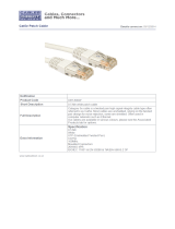
Figure 1-1 Front and Rear Panels
*. If an SFP transceiver is plugged in, the corresponding RJ-45 port is disabled for ports 25-26.
Slave
Stack
Master
UplinkUplink
PWR
Diag
RPU
1
2
3
4
5
6
7
8
9
10
11
12 13
14 15
16 17
18 19 20 21
22 23
24
27/Down
28/Up
25 26
o n e
level
®
GSW-2692
100-240V~ 50-60Hz1.5A
RPU
DC
12V 4.5A
Console
10/100 Mbps RJ-45 Ports
Port Status Indicators
Stacking Ports
1000BASE-T/SFP Ports
System Indicators
Power Socket
Redundant Power Socket
Console Port

Introduction
1-2
1
Switch Architecture
The GSW-2692 employs a wire-speed, non-blocking switching fabric. This permits
simultaneous wire-speed transport of multiple packets at low latency on all ports.
The switch also features full-duplex capability on all ports, which effectively doubles
the bandwidth of each connection.
The switch uses store-and-forward switching to ensure maximum data integrity. With
store-and-forward switching, the entire packet must be received into a buffer and
checked for validity before being forwarded. This prevents errors from being
propagated throughout the network.
The switch includes built-in stacking ports that enable up to eight units to be
connected together through a 4 Gbps stack backplane. The switch stack can be
managed from a master unit using a single IP address.
Network Management Options
With a comprehensive array of LEDs, the GSW-2692 switch provides “at a glance”
monitoring of network and port status. The switch can be managed over the network
with a web browser or Telnet application, or via a direct connection to the console
port. The switch includes a built-in network management agent that allows it to be
managed in-band using SNMP or RMON (Groups 1, 2, 3, 9) protocols. It also has an
RS-232 serial port (DB-9 connector) on the front panel for out-of-band management.
A PC may be connected to this port
for configuration and monitoring out-of-band via a
null-modem serial cable. (See Appendix B for wiring options.)
For a detailed description of the advanced features, refer to the Management Guide.
Description of Hardware
10BASE-T/100BASE-TX Ports
The GSW-2692 switch base unit contains 24 10BASE-T/100BASE-TX RJ-45 ports.
All ports support automatic MDI/MDI-X operation, so you can use straight-through
cables for all network connections to PCs or servers, or to other switches or hubs.
(See “10BASE-T/100BASE-TX Pin Assignments” on page B-1.)
Each of these ports support auto-negotiation, so the optimum transmission mode
(half or full duplex), and data rate (10 or 100 Mbps) can be selected automatically. If
a device connected to one of these ports does not support auto-negotiation, the
communication mode of that port can be configured manually.
Each port also supports IEEE 802.3x auto-negotiation of flow control, so the switch
can automatically prevent port buffers from becoming saturated.

Description of Hardware
1-3
1
1000BASE-T/SFP Ports
These are combination Gigabit RJ-45 ports with shared Small Form Factor
Pluggable (SFP) transceiver slots (See Figure 1-1, Ports 25-26). If an SFP
transceiver (purchased separately) is installed in a slot and has a valid link on the
port, the associated RJ-45 port is disabled.
The 1000BASE-T RJ-45 ports support automatic MDI/MDI-X operation, so you can
use straight-through cables for all network connections to PCs or servers, or to other
switches or hubs. (See “1000BASE-T Pin Assignments” on page B-3.)
Stacking Ports
The unit provides two stacking ports that provide a 4 Gbps stack backplane
connection. Up to eight switches can be connected together using Category 5
Ethernet cables (purchased separately). The Master button enables one switch in
the stack to be selected as the master. This is the unit through which you manage
the entire stack.
The stacking ports can also be used as normal Ethernet ports in standalone mode
by pressing the Uplink button.
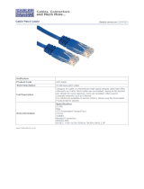
Figure 1-2 Stacking Ports
Slave
Stack
Master
UplinkUplink
PWR
Diag
RPU
23
24
27/Down
28/Up
25 26
o n e
level
®
GSW-2692
Master Button
Uplink Button
Stacking Ports

Introduction
1-4
1
Port and System Status LEDs
The GSW-2692 includes a display panel for key system and port indications that
simplify installation and network troubleshooting. The LEDs, which are located on
the front panel for easy viewing, are shown below and described in the following
tables.
Figure 1-3 Port LEDs
Table 1-1 Port Status LEDs
LED Condition Status
Fast Ethernet Ports (Ports 1-24)
(Link/Activity) On/Flashing
Amber
Port has established a valid 10 Mbps network connection.
Flashing indicates activity.
On/Flashing
Green
Port has established a valid 100 Mbps network connection.
Flashing indicates activity.
Off There is no valid link on the port.
Gigabit Ethernet Ports (Ports 25-26, and Ports 27-28 when stacking is not implemented)
(Link/Activity) On/Flashing
Amber
Port has established a valid 10/100 Mbps network connection.
Flashing indicates activity.
On/Flashing
Green
Port has established a valid 1000 Mbps network connection.
Flashing indicates activity.
Off There is no valid link on the port.
1
2
3
4
5
6
7
8
9
10
11 12
Port Status LEDs

Description of Hardware
1-5
1
Figure 1-4 System LEDs
Table 1-2 System Status LEDs
LED Condition Status
PWR On Green The unit’s internal power supply is operating normally.
On Amber The unit’s internal power supply has failed.
Off The unit has no power connected.
Diag On Green The system diagnostic test has completed successfully.
Flashing Green The system diagnostic test is in progress.
On Amber The system diagnostic test has detected a fault.
RPU Green A redundant power unit is attached and is in backup or
active mode.
Amber There is a fault in the redundant power unit.
Off There is no redundant power unit currently attached.
Stack Master Flashing Amber An initial power-on state during which the stack
configuration is detected.
Green This switch is acting as the Master unit in the stack.
Amber This switch is acting as a Slave unit in the stack.
PWR
Diag
RPU
28/Up
26
o n e
level
®
GSW-2692
System LEDs

Introduction
1-6
1
Power Supply Receptacles
There are two power receptacles on the
rear panel of the switch. The standard
power receptacle is for the AC power cord. The receptacle labeled “RPU” is for the
optional Redundant Power Unit (RPU)
.
Figure 1-5 Power Supply Receptacles
Features and Benefits
Connectivity
• 24 100BASE-TX ports, 2 1000BASE-T ports, and 2 combination 1000BASE-T/
SFP ports for easy integration and for protection of your investment in legacy LAN
equipment.
• Auto-negotiation enables each RJ-45 port to automatically select the optimum
speed (10, 100 or 1000 Mbps), and the communication mode (half or full duplex)
if this feature is supported by the attached device; otherwise the port can be
configured manually.
• 100BASE-TX and 1000BASE-T RJ-45 ports support auto MDI/MDI-X pinout
configuration.
• Unshielded (UTP) cable supported on all RJ-45 ports: Category 3 or better for
10 Mbps connections, Category 5 or better for 100 Mbps connections, and
Category 5, 5e or 6 for 1000 Mbps connections.
• IEEE 802.3-2002 Ethernet, Fast Etherne
t, Gigabit Ethernet compliance ensures
compatibility with standards-based hubs, network cards and switches from any
vendor.
• Provides stacking capability via RJ-45 ports with 4 Gbps stacking bandwidth. Up
to 8 units can be stacked together.
100-240V~ 50-60Hz 1.5A
RPU
DC
12V 4.5A

Features and Benefits
1-7
1
Expandability
• 2 Small Form Factor Pluggable (SFP) tr
ansceiver slots (shared with 1000BASE-T
ports)
• Supports 1000BASE-SX, 1000BASE-LX and 1000BASE-ZX SF
P transceivers.
Performance
• Transparent bridging
• Aggregate duplex bandwidth of up to 12.8 Gbps
• Switching table with a total of 8K MAC address entries
• Provides store-and-forward switching
• Wire-speed filtering and forwarding
• Supports flow control, using back pressure for half duplex and IEEE 802.3x for full
duplex
• Broadcast storm control
Management
• “At-a-glance” LEDs for easy troubleshooting
• Network management agent:
- Manages switch in-band or out-of-band
- Supports SSH, Telnet, SNMP (v1/v2), RMON (4 groups) and web-based
interface

Introduction
1-8
1
/