Weidmuller IE-GWT-MB-2TX-1RS232/485 User manual
- Category
- Networking
- Type
- User manual
This manual is also suitable for

Modbus TCP / RTU Gateway
Manual
for models
IE-GW-MB-2TX-1RS232/485
IE-GWT-MB-2TX-1RS232/485
First Edition, May 2014
1536320000/00/05.14

- 2 -
Modbus TCP / RTU Gateway
Manual
IE-GW-MB-2TX-1RS232/485
IE-GWT-MB-2TX-1RS232/485
The software described in this manual is furnished under a license agreement and may be used only in
accordance with the terms of that agreement.
Copyright Notice
Copyright 2014 Weidmüller Interface GmbH &Co. KG.
All rights reserved.
Reproduction without permission is prohibited.
Disclaimer
Information in this document is subject to change without notice and does not represent a commitment
on the part of Weidmüller.
Weidmüller provides this document
including, but not limited to, its particular purpose. Weidmüller reserves the right to make
improvements and/or changes to this manual, or to the products and/or the programs described in this
manual, at any time.
Information provided in this manual is intended to be accurate and reliable. However, Weidmüller
assumes no responsibility for its use, or for any infringements on the rights of third parties that may
result from its use.
This product might include unintentional technical or typographical errors. Changes are periodically
made to the information herein to correct such errors, and these changes are incorporated into new
editions of the publication.

- 3 -
Contact Information
Weidmüller Interface GmbH & Co. KG
Postbox 3030
32760 Detmold
Klingenbergstraße 16
32758 Detmold
Germany
Phone: +49(0) 5231 14-0
Fax:+49(0) 5231 14-2083
E-Mail [email protected]
Internet www.weidmueller.com

- 4 -
Contents
1. INTRODUCTION .................................................................................................... 5
1.1 Overview Modbus TCP/RTU Gateway ........................................................................................... 5
1.2 Modbus Basics ................................................................................................................................ 6
2. PACKAGE CHECKLIST ........................................................................................ 8
3. OVERVIEW PRODUCT FEATURES ...................................................................... 8
4. HARDWARE DESCRIPTION ................................................................................. 9
4.1 Panel Layout .................................................................................................................................... 9
4.2 LED Indicators ................................................................................................................................. 9
4.3 Dimensions .................................................................................................................................... 10
4.4 Jumpers .......................................................................................................................................... 11
4.5 DIN-Rail, Wall Mounting ................................................................................................................ 12
4.6 Pin Assignments ............................................................................................................................ 13
4.6.1 DB9 male connector (RS232) ................................................................................................... 13
4.6.2 Terminal Block (RS-422, RS-485) ............................................................................................ 13
4.6.3 Power Input, Relay Output ........................................................................................................ 13
5. SPECIFICATIONS ................................................................................................ 14
6. GETTING STARTED ............................................................................................ 16
6.1 Reset to factory default values by external Reset button ............................................................ 16
6.2 Connecting Power ........................................................................................................................ 16
6.3 Connecting Serial Devices ........................................................................................................... 16
6.4 Connecting to a Host or Network ................................................................................................. 16
7. DEVICE CONFIGURATION ................................................................................. 17
7.1 Device configuration by Web-Interface ....................................................................................... 17
..................................................................................................... 18
.............................................................................................. 23
......................................................................................... 30
.................................................................................................................. 33
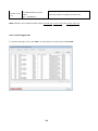
7.2 Configuration and Monitoring via PC-based tool Modbus Gateway Administrator ............... 34
8. TYPICAL APPLICATIONS ................................................................................... 51
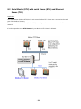
8.1 Ethernet Master (TCP) with multiple serial Slaves (RTU) ....................................................... 51
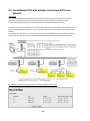
8.2 Serial Master (RTU) with serial Slaves (RTU) and Ethernet Slaves (TCP) ............................ 52
8.3 Serial Master (RTU) with multiple serial Slaves (RTU) over Ethernet .................................... 53

- 5 -
1. Introduction
Welcome to the Weidmüller Modbus TCP/RTU gateways. All models feature easy integration of
Modbus TCP to Modbus RTU/ASCII and feature RS-232/422/485 ports for Modbus serial
communication.
1.1 Overview Modbus TCP/RTU Gateway
The Weidmüller Modbus TCP/RTU Gateways provides users with
Seamless integration of Ethernet and serial Modbus devices
Powerful operation modes to handle almost any Modbus application
Windows utility for easy setup and traffic monitoring
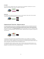
Seamless integration of Ethernet and serial Modbus devices
Modbus is one of the most popular automation protocols in the world, supporting traditional
RS-232/422/485 devices and recently developed Ethernet devices. Many industrial devices, such as
PLCs, DCSs, HMIs, instruments, and meters, use Modbus as their communication standard. However,
the Ethernet-based Modbus protocol is different from the original serial-based protocols that a
communication gateway is needed as a bridge for integration.
In order to integrate Modbus networks, the Modbus TCP/RTU Gateway includes an Ethernet interface
and a serial port that supports RS-232, RS-422 and RS-485 communication. It automatically and
intelligently translates between Modbus TCP (Ethernet) and Modbus ASCII/RTU (serial) protocols,
allowing Ethernet-based controllers to communicate with instruments over RS-485 without additional
programming or any other software-based adaptions.
Powerful operation modes to handle almost any Modbus application
With the Modbus protocol, devices must be clearly defined as either masters or slaves. The Modbus
Gateway can be configured to operate as master or slave mode at the serial port. In the slave mode it
is possible that several Ethernet masters control serial slaves simultaneously, in the Master mode a
serial master can control multiple Ethernet slaves.
Extra address mapping and exception parameters are provided to ensure that most situations can be
handled.
Windows utility for easy setup and traffic monitoring
Alternatively to the Web-based configuration of the Gateway the Windows utility Modbus Gateway
Administrator can be used for device configuration. This utility has an integrated search function to
detect the IP addresses of LAN-connected Modbus Gateways. This is very helpful if the IP address of
a Modbus TCP/RTU Gateway is unknown. Additionally traffic monitoring functions help you
troubleshoot Modbus communication problems by tracking items such as connection status and
address translation errors.

- 6 -
1.2 Modbus Basics
Introduction
Modbus is one of the most popular automation protocols in the world. It supports both serial and
Ethernet devices. Many industrial devices, such as PLCs, DCSs, HMIs, instruments, meters, motors,
and drivers use Modbus as their communication standard.
Devices are either Masters or Slaves
All Modbus devices are classified as either a master or a slave. Masters initiate all communication with
slaves and do not communicate to other masters. Slaves are completely passive and communicate
only
Slaves are identified by ID
Each Modbus slave in a system is assigned a unique ID between 1 and 247. Whenever a master
sends a request, the request must include the ID of the intended recipient. Master devices themselves
have no ID.
0 Broadcast address
1-247 Slave individual address
258-255 Reserved
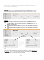
Communication is done by Request and Response
Modbus communication generally is running by request and response. A master sends a request and
an addressed
the next request. For broadcast commands no response is expected. This is illustrated by three
scenarios as follows:
Normal communication (Peer-to-Peer)
The master sends a request to the slave. The slave sends a response with the requested information.

- 7 -
Exception
The master sends a request to the slave. The slave may not support the command or an error is
detected. As result the slave sends an exception to the master.
Broadcast
The master sends a broadcast command, such as a reset command. Every slave on the network
accepts the command. No response is sent to the master.
Requests Need a Time Limit Response timeout
The original Modbus protocol was not designed for simultaneous requests or simultaneous masters,
so only one request on the network can be handled at a time. When a master sends a request to a
slave, no other communication may be initiated until the slave responds. The Modbus protocol
specifies that masters use a response timeout function to identify when a slave is nonresponsive due
to device or communication failure. This function allows a master to discard a request if no response is
received timely.
To integrate a wide range of devices (with different baudrates or line conditions) into a Modbus
communication a limit for a response time is not set and can be determined by the manufacturers.
However, this also makes it difficult for system integrators to know what response timeout value to use
during configuration, especially with older or proprietary devices.
The Weidmüller Modbus Gateway provides a speciual function that tests all attached devices and
recommends a response timeout value. This function saves considerable time and effort for system
integrators, and results in more accurate timeout settings.

- 8 -
2. Package Checklist
All models of Weidmüller Modbus TCP/RTU Gateways are shipped with the following items:
1 Modbus Gateway
Hardware Installation Guide (includes Download-Links for this user manual and firmware
updates)
3. Overview Product Features
Integration of Modbus TCP and Modbus RTU/ASCII networks
Up to 31 Modbus RTU/ASCII slaves can be connected to the serial port (RS-485)
Up to 32 Modbus TCP slaves can be connected to a Modbus RTU/ASCII master
Up to 16 Modbus TCP masters can control Modbus RTU/ASCII slaves simultaneously
Configuration via Web interface, Telnet or Windows utility Modbus TCP/RTU Gateway
Administrator
2 RJ45 Ethernet ports 10/100 (TX)
1 high speed serial interface (SubD connector for RS232, Terminal block for RS422/485)
Software-selectable RS-232/485/422 communication
High speed serial interface supporting baud rates up to 921.6 Kbps
ProCOM: Virtual Serial Port for flexible Modbus to Modbus TCP communication

- 9 -
4. Hardware description
The hardware information is valid for models
IE-GW-MB-2TX-1RS232/485 Standard Temperature range model (0 to 55°C)
and IE-GWT-MB-2TX-1RS232/485 Extended Temperature range model (-40 to 75°C)
4.1 Panel Layout
4.2 LED Indicators
Name
Color
Function
PWR1
Red
Power is being supplied to the power input.
PWR2
Red
Power is being supplied to the power input.
RDY
Red
Steady on: Power is on and unit is booting up.
Blinking: Indicates an IP conflict, or DHCP or BOOTP server is not
responding properly.
Green
Steady on: Power is on and unit is running properly.
Blinking: Unit is responding to software function Locate.
Off
Power is off or power error condition exists.
Ethernet
Orange
10 Mbps Ethernet connection.
Green
100 Mbps Ethernet connection.
Off
Ethernet cable is disconnected, or has a short.

- 10 -
P1
Orange
Serial port is receiving data.
Green
Serial port is transmitting data.
Off
No data is being transmitted or received through the serial port.
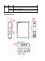
4.3 Dimensions

- 11 -
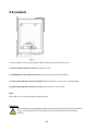
4.4 Jumpers
The DIP switches are located beneath the DIP switch panel on the side of the unit.
set switch 3 to ON.
To disable the set switch 3 to OFF (default setting).
set DIP switches 1 and 2 to OFF (default setting).
To set set DIP switches 1 and 2 to ON.
Note:
DIP switch 4 is not used (reserved for future function).
Attention:
device when using the RS-232 interface.
Doing so will degrade the RS-232 signals and reduce the effective communication
distance.

- 12 -
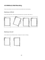
4.5 DIN-Rail, Wall Mounting
There are two sliders on the rear side of the unit for DIN-rail and wall mounting.
Mounting on a DIN-rail
Pull out the bottom slider, latch the unit onto the DIN-rail, and push the slider back in.
Mounting on the wall
Pull out both the top and bottom sliders and align the screws accordingly.

- 13 -
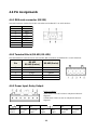
4.6 Pin Assignments
4.6.1 DB9 male connector (RS232)
Use DB9 connector (male) for RS-232 connections to Modbus RTU or ASCII devices.
4.6.2 Terminal Block (RS-422, RS-485)
Use terminal block connector for RS-422 and RS-485 connections to Modbus RTU or ASCII devices.
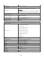
4.6.3 Power Input, Relay Output
Relais conditions:
Open when Power-off or when a relay-based alarm is
triggered.
Closed when Power-on and no relay-based alarm is
triggered.
V2+
V2-
V1+
V1-
Shielded
Ground
DC Power
Input 2
DC Power
Input 2
Relay
Output
Relay
Output
DC Power
Input 1
DC Power
Input 1
Pin RS-232
1DCD
2 RxD
3 TxD
4 DTR
5 GND
6 DSR
7 RTS
8 CTS
Pin
RS-422
RS-485 (4-wire)
RS-485 (2-wire)
1 TxD+ ---
2 TxD- ---
3 RxD+ Data+
4 RxD- Data-
5 GND GND

- 14 -
5. Specifications
Software Features
Operation Modes
RTU Slave, RTU Master, ASCII Slave, ASCII Master
Multi-Masters and Multi-Request
16 simultaneous TCP masters, 32 simultaneous requests for each
TCP master
Serial redirection, Priority control
Power Requirements
Power Input
12 to 48 VDC
Power Consumption
Max. 435 mA @ 12 VDC,
Max. 130 mA @ 48 VDC
Physical Characteristics
Housing
Plastic, IP30
Dimensions
29 (W) x 124.5 (H) x 89.2(D) mm
Installation
DIN-Rail Mounting
Ethernet Interfaces
Ethernet ports
2 RJ45 ports 10/100BaseT(X), Auto MDI/MDI-X
Magnetic isolation protection (RJ45)
1.5 kV built-in
Serial Interfaces
Serial ports
1
Serial connector types
DB9 RS-232, 5-pin terminal block for RS-422/485
Signals
RS-232: TxD, RxD, RTS, CTS, DTR, DSR, DCD, GND
RS-422: Tx+, Tx-, Rx+, Rx-, GND
RS-485 (2-wire): Data+, Data-, GND
RS-485 (4-wire): Tx+, Tx-, Rx+, Rx-, GND
RS-485 data direction control
ADDC® (automatic data direction control)
Serial line protection
15 KV ESD protection for all signals
Pull high/low resistor for RS-485
1 kOhm, 150 kOhm
Terminating resistor for RS-485
120 Ohm
Serial Communication Parameters
Baudrates
Baud rate 50 bit/s to 921.6 kbit/s
Parity
None, Even, Odd, Space, Mark
Data Bits
7, 8
Stop Bits
1, 2

- 15 -
Flow Control
RTS/CTS, XON/XOFF
Alarm Contact
Relay Output
1 relay output with a current capacity of 1 A @ 30 VDC
Conditions:
Open when Power-off or when a relay-based alarm is triggered
Closed when Power-on and no relay-based alarm is triggered
Environmental Limits
Operating Temperature
0 to 55°C (32 to 131°F),
-40 to 75°C (-40 to 167°F) for T model
Storage Temperature
-40 to 85 °C (-40 to 185 °F)
Operating Humidity
5 to 95% RH
Regulary Approvals
EMC standards
FCC Part 15 Subpart B Class A
EN 55022 Class A
EN 61000-4-2 (ESD), Level 3
EN 61000-4-3 (RS), Level 3
EN 61000-4-4 (EFT), Level 4
EN 61000-4-5 (Surge), Level 3
EN 61000-4-6 (CS), Level 3
EN 61000-4-8
EN 61000-4-11
Security
UL 508
Hazardous Location
UL/cUL Class 1 Div 2 Groups A, B, C, D
Free fall
according to IEC 60068-2-32
Shock
according to IEC 60068-2-27
Vibration
according to IEC 60068-2-6
MTBF
Time
210.794 hrs
Database
Telcordia (Bellcore), GB
WARRANTY
Time Period
5 years

- 16 -
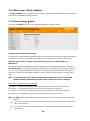
6. Getting Started
6.1 Reset to factory default values by external Reset button
The reset button located on top side of the housing - is used to load factory defaults. Use a pointed
object such as a straightened paper clip to hold the reset button down for 5 seconds. Release the
reset button when the Ready LED stops blinking.
6.2 Connecting Power
Connect the unit to a power source of range 12 to 48 VDC. For pin assignments of power terminal
block please refer to chapter 4.6 (Pin Assignments).
Note: The unit does not have an on/off switch. It automatically turns on when it receives power. The
PWR LED on the top panel will glow to indicate that the unit is receiving power.
6.3 Connecting Serial Devices
serial devices, depending on the 2 different connector types:
For RS232 connections the DB9 male connector has to be used. You can either use a standard
DCE/DTE cable or you may make your own customized serial cable to connect a serial device to the
chapter 4.6 (Pin
Assignments).
For connecting multiple devices via a RS-485 multidrop network the 5-pin terminal block has to be
used. All devices that are connected to the serial port must use the same protocol (i.e., either Modbus
RTU or Modbus ASCII). For the pin assignments of the uterminal block connector please refer
chapter 4.6 (Pin Assignments).
RS-485 Termination and Pull High/Low Resistors
In some critical RS-485 environments, you may need to add termination resistors to prevent the
reflection of serial signals. When using termination resistors, it is important to set the pull high/low
resistors correctly so that the electrical signal is not corrupted. For serial port DIP switches are used to
set the pull high/low resistor values. A built- also be enabled.
To modify the termination and pull high/low resistor settings, please refer to chapter 4.4 (Jumpers).
6.4 Connecting to a Host or Network
ports
behave like an unmanaged 2-Port-Switch. For the connection to a host or an Ethernet Switch use a
standard straight-through or a crossover Ethernet cable.
live Ethernet connection.

- 17 -
7. Device Configuration
The Modbus TCP/RTU Gateway can be configured via one of the 2 Ethernet ports by
Integrated Webinterface
Telnet Console
or by PC-based
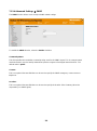
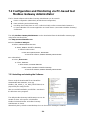
7.1 Device configuration by Web-Interface
The Web interface can be accessed via IP address 192.168.1.110 and subnet mask 255.255.255.0
(Factory default values).
range 192.168.1.0 / 255.255.255.0
Start a Web browser and enter the I
line (http://192.168.1.110).
After the appearance of the login prompt, please enter following login data (factory settings):
User name: admin
Password: Detmold
After a few moments the home page will appear as shown below.

- 18 -
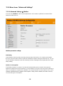
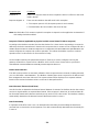
7.1.1 Basic Settings
The Basic Settings section includes the most common settings required by administrators to maintain
and control a Weidmüller Modbus Gateway.
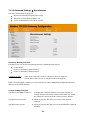
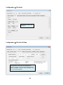
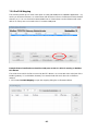
7.1.1.1 Basic Settings Mode
The menu item Mode allows users to configure the Modbus operation modes.
Operation mode of physical serial port
The operation mode determines whether the device(s) that are connected to the serial port will operate
as master or as slave(s), and whether the Modbus RTU or Modbus ASCII protocol will be used.
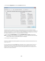
Operation mode of up to 4 virtual COM-Ports (ProCom) which can be installed on a
Windows-PC
- running as
RTU/ASCII Master - to communicate with RTU/ASCII Slaves via Ethernet and the Modbus Gateway.
PCs can use ProCOM-Port driver to communicate over Ethernet with serial devices
(which are connected to the Modbus Gateway) as if they were connected to the PCe COM
ports.
Note: To use this feature you need to install the virtual COM-Ports (ProCom) with utility
Modbus Gateway Administrator. Please refer to chapter 7.2.9 how to configure.
There are four operation modes as follows:
RTU Slave One ore more Modbus RTU slave(s) shall be connected to the serial port.
RTU Master One Modbus RTU master shall be connected to the serial port.
ASCII Slave One ore more Modbus ASCII slave(s) shall be connected to the serial port.
ASCII Master One Modbus ASCII master shall be connected to the serial port.
Note: The Mode setting refers allways to the serial port and has to be set same as the connecting
device(s).
If you have connected one or more serial devices running as slave(s) then select either RTU
Slave or ASCII Slave.
If you have connected a serial Master (only 1 is allowed) then select either RTU Master or
ASCII Master.

- 19 -
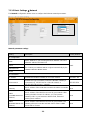
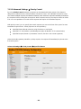
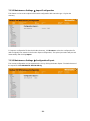
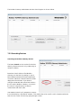
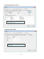
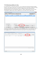
7.1.1.2 Basic Settings Network
The Network configuration allows users to configure the Ethernet network parameters.
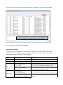
Network parameter settings
Setting
Description
Factory Default
IP Configuration
Static
unit's
default IP address 192.168.1.110
Static
DHCP
The Gatewayassigned automatically by the
DHCP/BOOTP
BootP
IP Parameters
IP address
Identifies the Modbus Gateway on a TCP/IP network.
192.168.1.110
Subnet mask
Identifies the type of network to which the Modbus Gateway is
connected (e.g., 255.255.0.0 for a Class B network, or
255.255.255.0 for a Class C network).
255.255.255.0
Gateway
The IP address of the router that connects the LAN to an outside
network.
None
DNS1
address)
The IP address of the DNS Server used by your network. After
entering the DNS Server's IP address, you can input the
Gateway's URL in your browser's address field, instead of
entering the IP address.
None
DNS2
address)
The IP address of the DNS Server used by your network. The
Gateway will try to locate the 2nd DNS Server if the 1st DNS
Server fails to connect.
None

- 20 -
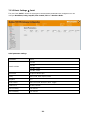
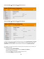
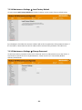
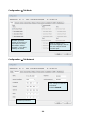
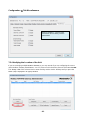
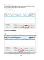
7.1.1.3 Basic Settings Serial
The menu item Serial is where the
configure Baud Rate, Parity, Stop Bit, Flow Control, FIFO and Interface Mode.
Serial parameter settings
Parameter
Value
Interface Mode
RS-232
RS-422
RS-485, 2-wire
RS-485, 4-wire
Baud Rate
50 bps to 961200 bps
Parity
None, Odd, Even, Space, Mark
Stop Bits
1, 2
Flow Control
None, Xon/Xoff, RTS/CTS, RTS Toggle
UART FIFO
Enable, Disable
RTS On Delay
0 to 100 ms
RTS Off Delay
0 to 100 ms
Page is loading ...
Page is loading ...
Page is loading ...
Page is loading ...
Page is loading ...
Page is loading ...
Page is loading ...
Page is loading ...
Page is loading ...
Page is loading ...
Page is loading ...
Page is loading ...
Page is loading ...
Page is loading ...
Page is loading ...
Page is loading ...
Page is loading ...
Page is loading ...
Page is loading ...
Page is loading ...
Page is loading ...
Page is loading ...
Page is loading ...
Page is loading ...
Page is loading ...
Page is loading ...
Page is loading ...
Page is loading ...
Page is loading ...
Page is loading ...
Page is loading ...
Page is loading ...
Page is loading ...
-
 1
1
-
 2
2
-
 3
3
-
 4
4
-
 5
5
-
 6
6
-
 7
7
-
 8
8
-
 9
9
-
 10
10
-
 11
11
-
 12
12
-
 13
13
-
 14
14
-
 15
15
-
 16
16
-
 17
17
-
 18
18
-
 19
19
-
 20
20
-
 21
21
-
 22
22
-
 23
23
-
 24
24
-
 25
25
-
 26
26
-
 27
27
-
 28
28
-
 29
29
-
 30
30
-
 31
31
-
 32
32
-
 33
33
-
 34
34
-
 35
35
-
 36
36
-
 37
37
-
 38
38
-
 39
39
-
 40
40
-
 41
41
-
 42
42
-
 43
43
-
 44
44
-
 45
45
-
 46
46
-
 47
47
-
 48
48
-
 49
49
-
 50
50
-
 51
51
-
 52
52
-
 53
53


Weidmuller IE-GWT-MB-2TX-1RS232/485 User manual
- Category
- Networking
- Type
- User manual
- This manual is also suitable for
Ask a question and I''ll find the answer in the document
Finding information in a document is now easier with AI
Related papers
Other documents
-
Moxa MGate MB3170/MB3270 Series User manual
-
-
-
Moxa Technologies MGATE MB3270I User manual
-
-
-
 Moxa Technologies MGate-4101-MB-PBS User manual
-
-
 Moxa Technologies MGate 5109 User manual
-

