
Motherboard
A55-C

ii
E7917
First Edition
January 2013
Copyright © 2013 ASUSTeK COMPUTER INC. All Rights Reserved.
No part of this manual, including the products and software described in it, may be reproduced,
transmitted, transcribed, stored in a retrieval system, or translated into any language in any form or by any
means, except documentation kept by the purchaser for backup purposes, without the express written
permission of ASUSTeK COMPUTER INC. (“ASUS”).
Product warranty or service will not be extended if: (1) the product is repaired, modied or altered, unless
such repair, modication of alteration is authorized in writing by ASUS; or (2) the serial number of the
product is defaced or missing.
ASUS PROVIDES THIS MANUAL “AS IS” WITHOUT WARRANTY OF ANY KIND, EITHER EXPRESS
OR IMPLIED, INCLUDING BUT NOT LIMITED TO THE IMPLIED WARRANTIES OR CONDITIONS OF
MERCHANTABILITY OR FITNESS FOR A PARTICULAR PURPOSE. IN NO EVENT SHALL ASUS, ITS
DIRECTORS, OFFICERS, EMPLOYEES OR AGENTS BE LIABLE FOR ANY INDIRECT, SPECIAL,
INCIDENTAL, OR CONSEQUENTIAL DAMAGES (INCLUDING DAMAGES FOR LOSS OF PROFITS,
LOSS OF BUSINESS, LOSS OF USE OR DATA, INTERRUPTION OF BUSINESS AND THE LIKE),
EVEN IF ASUS HAS BEEN ADVISED OF THE POSSIBILITY OF SUCH DAMAGES ARISING FROM ANY
DEFECT OR ERROR IN THIS MANUAL OR PRODUCT.
SPECIFICATIONS AND INFORMATION CONTAINED IN THIS MANUAL ARE FURNISHED FOR
INFORMATIONAL USE ONLY, AND ARE SUBJECT TO CHANGE AT ANY TIME WITHOUT NOTICE,
AND SHOULD NOT BE CONSTRUED AS A COMMITMENT BY ASUS. ASUS ASSUMES NO
RESPONSIBILITY OR LIABILITY FOR ANY ERRORS OR INACCURACIES THAT MAY APPEAR IN THIS
MANUAL, INCLUDING THE PRODUCTS AND SOFTWARE DESCRIBED IN IT.
Products and corporate names appearing in this manual may or may not be registered trademarks or
copyrights of their respective companies, and are used only for identication or explanation and to the
owners’ benet, without intent to infringe.
Offer to Provide Source Code of Certain Software
This product contains copyrighted software that is licensed under the General Public License (“GPL”),
under the Lesser General Public License Version (“LGPL”) and/or other Free Open Source Software
Licenses. Such software in this product is distributed without any warranty to the extent permitted by the
applicable law. Copies of these licenses are included in this product.
Where the applicable license entitles you to the source code of such software and/or other additional data,
you may obtain it for a period of three years after our last shipment of the product, either
(1) for free by downloading it from http://support.asus.com/download
or
(2) for the cost of reproduction and shipment, which is dependent on the preferred carrier and the location
where you want to have it shipped to, by sending a request to:
ASUSTeK Computer Inc.
Legal Compliance Dept.
15 Li Te Rd.,
Beitou, Taipei 112
Taiwan
In your request please provide the name, model number and version, as stated in the About Box of the
product for which you wish to obtain the corresponding source code and your contact details so that we
can coordinate the terms and cost of shipment with you.
The source code will be distributed WITHOUT ANY WARRANTY and licensed under the same license as
the corresponding binary/object code.
This offer is valid to anyone in receipt of this information.
ASUSTeK is eager to duly provide complete source code as required under various Free Open Source
Software licenses. If however you encounter any problems in obtaining the full corresponding source
code we would be much obliged if you give us a notication to the email address [email protected], stating
the product and describing the problem (please DO NOT send large attachments such as source code
archives, etc. to this email address).

iii
Contents
Safety information ...................................................................................................... vi
About this guide ........................................................................................................ vii
A55-C specications summary ................................................................................. ix
Package contents ....................................................................................................... xi
Product introduction
1.1 Special features ............................................................................................ 1-1
1.1.1 Product highlights ...........................................................................1-1
1.1.2 ASUS Exclusive Features ...............................................................1-1
1.2 Before you proceed ...................................................................................... 1-3
1.3 Motherboard overview ................................................................................. 1-4
1.3.1 Placement direction ........................................................................1-4
1.3.2 Screw holes ....................................................................................1-4
1.3.3 Motherboard layout .........................................................................1-5
1.3.4 Layout contents ...............................................................................1-6
1.4 Accelerated Processing Unit (APU) ............................................................ 1-6
1.4.1 APU installation ...............................................................................1-7
1.4.2 APU heatsink and fan assembly installation ...................................1-8
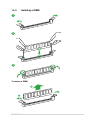
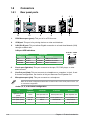
1.5 System memory .......................................................................................... 1-10
1.5.1 Overview .......................................................................................1-10
1.5.2 Memory congurations ..................................................................1-10
1.5.3 Installing a DIMM .......................................................................... 1-15
1.6 Expansion slots .......................................................................................... 1-16
1.6.1 Installing an expansion card .........................................................1-16
1.6.2 Conguring an expansion card ..................................................... 1-16
1.6.3 PCI slots ........................................................................................1-16
1.6.4 PCI Express x1 slots .....................................................................1-16
1.6.5 PCI Express x16 slot .....................................................................1-16
1.7 Jumpers.......................................................................................................1-18
1.8 Connectors .................................................................................................. 1-20
1.8.1 Rear panel ports ...........................................................................1-20
1.8.2 Internal connectors .......................................................................1-22
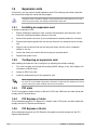
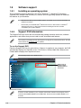
1.9 Software support ........................................................................................ 1-28
1.9.1 Installing an operating system ......................................................1-28
1.9.2 Support DVD information ..............................................................1-28

iv
BIOS information
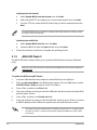
2.1 Managing and updating your BIOS ............................................................. 2-1
2.1.1 ASUS Update utility ........................................................................2-1
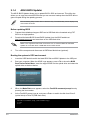
2.1.2 ASUS EZ Flash 2 ............................................................................2-2
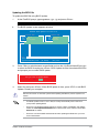
2.1.3 ASUS CrashFree BIOS 3 utility ......................................................2-3
2.1.4 ASUS BIOS Updater .......................................................................2-4
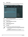
2.2 BIOS setup program ..................................................................................... 2-6
2.3 Main menu ................................................................................................... 2-10
2.3.1 System Language [English] .......................................................... 2-10
2.3.2 System Date [Day xx/xx/xxxx] ....................................................... 2-10
2.3.3 System Time [xx:xx:xx] .................................................................2-10
2.3.4 Security .........................................................................................2-10
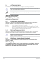
2.4 Ai Tweaker menu ........................................................................................ 2-12
2.4.1 Ai Overclock Tuner [Auto] ............................................................. 2-12
2.4.2 Memory Frequency [Auto] ............................................................. 2-12
2.4.3 EPU Power Saving Mode [Disabled] ............................................2-12
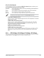
2.4.4 DIGI+ VRM .................................................................................... 2-13
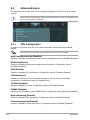
2.5 Advanced menu .......................................................................................... 2-14
2.5.1 CPU Conguration ........................................................................2-14
2.5.2 SATA Conguration .......................................................................2-15
2.5.3 USB Conguration ........................................................................ 2-16
2.5.4 NB Conguration ........................................................................... 2-16
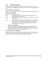
2.5.5 Onboard Devices Conguration ....................................................2-17
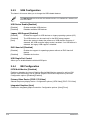
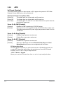
2.5.6 APM .............................................................................................. 2-18
2.5.7 Network Stack ...............................................................................2-19
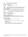
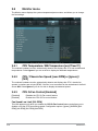
2.6 Monitor menu .............................................................................................. 2-20
2.6.1 CPU Temperature / MB Temperature [xxxºC/xxxºF]...................... 2-20
2.6.2 CPU / Chassis fan Speed [xxxx RPM] or [Ignore] / [N/A] .............. 2-20
2.6.3 CPU Q-Fan Control [Enabled] ......................................................2-20
2.6.4 CPU Voltage, 3.3V Voltage, 5V Voltage, 12V Voltage .................. 2-21

v
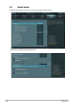
2.7 Boot menu ................................................................................................... 2-22
2.7.1 Fast Boot [Enabled] ......................................................................2-23
2.7.2 Full Screen Logo [Enabled] ........................................................... 2-23
2.7.3 Post Delay Time [3 sec] ................................................................ 2-24
2.7.4 Bootup NumLock State [On] ......................................................... 2-24
2.7.5 Wait for ‘F1’ If Error [Enabled] ....................................................... 2-24
2.7.6 Option ROM Messages [Force BIOS] ...........................................2-24
2.7.7 Interrupt 19 Capture [Postponed] .................................................. 2-24
2.7.8 Setup Mode [EZ Mode] .................................................................2-24
2.7.9 CSM (Compatibility Support Module) ............................................ 2-24
2.7.10 Secure Boot .................................................................................. 2-25
2.7.11 Boot Option Priorities ....................................................................2-26
2.7.12 Boot Override ................................................................................2-26
2.8 Tools menu ..................................................................................................2-27
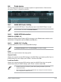
2.8.1 ASUS EZ Flash 2 Utility ................................................................2-27
2.8.2 ASUS SPD Information .................................................................2-27
2.8.3 ASUS O.C. Prole ......................................................................... 2-27
2.9 Exit menu .................................................................................................... 2-28
Appendices
Notices ..................................................................................................................... A-1
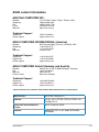
ASUS contact information ...................................................................................... A-3

vi
Safety information
Electrical safety
To prevent electrical shock hazard, disconnect the power cable from the electrical outlet
before relocating the system.
When adding or removing devices to or from the system, ensure that the power cables
for the devices are unplugged before the signal cables are connected. If possible,
disconnect all power cables from the existing system before you add a device.
Before connecting or removing signal cables from the motherboard, ensure that all
power cables are unplugged.
Seek professional assistance before using an adapter or extension cord. These devices
could interrupt the grounding circuit.
Ensure that your power supply is set to the correct voltage in your area. If you are not
sure about the voltage of the electrical outlet you are using, contact your local power
company.
If the power supply is broken, do not try to x it by yourself. Contact a qualied service
technician or your retailer.
Operation safety
Before installing the motherboard and adding devices on it, carefully read all the manuals
that came with the package.
Before using the product, ensure all cables are correctly connected and the power
cables are not damaged. If you detect any damage, contact your dealer immediately.
To avoid short circuits, keep paper clips, screws, and staples away from connectors,
slots, sockets and circuitry.
Avoid dust, humidity, and temperature extremes. Do not place the product in any area
where it may become wet.
Place the product on a stable surface.
If you encounter technical problems with the product, contact a qualied service
technician or your retailer.
•
•
•
•
•
•
•
•
•
•
•
•

vii
About this guide
This user guide contains the information you need when installing and conguring the
motherboard.
How this guide is organized
This guide contains the following parts:
• Chapter 1: Product introduction
This chapter describes the features of the motherboard and the new technology it
supports.
• Chapter 2: BIOS information
This chapter tells how to change system settings through the BIOS Setup menus.
Detailed descriptions of the BIOS parameters are also provided.
Where to nd more information
Refer to the following sources for additional information and for product and software
updates.
1. ASUS websites
The ASUS website provides updated information on ASUS hardware and software
products. Refer to the ASUS contact information.
2. Optional documentation
Your product package may include optional documentation, such as warranty yers,
that may have been added by your dealer. These documents are not part of the
standard package.

viii
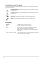
Conventions used in this guide
To ensure that you perform certain tasks properly, take note of the following symbols used
throughout this manual.
DANGER/WARNING: Information to prevent injury to yourself when trying to
complete a task.
CAUTION: Information to prevent damage to the components when trying to
complete a task
IMPORTANT: Instructions that you MUST follow to complete a task. .
NOTE: Tips and additional information to help you complete a task.
Typography
Bold text Indicates a menu or an item to select.
Italics
Used to emphasize a word or a phrase.
<Key> Keys enclosed in the less-than and greater-than sign
means that you must press the enclosed key.
Example: <Enter> means that you must press the Enter or
Return key.
<Key1> + <Key2> + <Key3> If you must press two or more keys simultaneously, the key
names are linked with a plus sign (+).

ix
(continued on the next page)
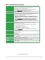
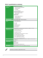
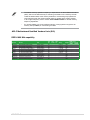
A55-C specications summary
APU FM2 socket for AMD® A-Series Accelerated Processor Unit (APU) with AMD
Radeon™ HD 7000 Series graphics, up to 4 CPU cores
Supports AMD® Turbo Core Technology 3.0
• The AMD® Turbo Core Technology 3.0 support depends on the APU types.
• Refer to www.asus.com for the AMD® APU support list.
Chipset AMD® A55 FCH
Memory 2 x 240-pin DIMM slots support a maximum 32GB unbuffered non-ECC
DDR3 1866/1600/1333/1066 MHz memory modules
Dual-channel memory architecture
• The maximum 32GB memory capacity can be supported with 16GB or above
DIMMs. ASUS will update the memory QVL once the DIMMs are available in the
market.
• Refer to www.asus.com for the latest Memory QVL (Qualied Vendors List).
• When you install a total memory of 4GB capacity or more, Windows® 32-bit
operating system may only recognize less than 3GB. We recommend a
maximum of 3GB system memory if you are using a Windows® 32-bit operating
system.
Graphics Integrated AMD® Radeon™ HD 7000 series graphics in Trinity APU
VGA output support: D-Sub port
- Supports D-Sub with a maximum resolution of 1920x1600@60Hz
- Supports Microsoft® DirectX 11
- Maximum shared memory of 2GB
- Supports AMD® Dual Graphics technology
* Refer to www.amd.com for a list of discrete GPUs that support Dual
Graphics.
Expansion slots 1 x PCIe 2.0 x16 slot
3 x PCIe 2.0 x1 slots
3 x PCI slots
Storage / RAID AMD® A55 FCH:
- 6 x Serial ATA 3.0Gb/s connectors with RAID 0, RAID 1, RAID 10 and
JBOD support
LAN Realtek® 8111F PCIe Gigabit LAN controller
Audio Realtek® ALC887 8-channel High Denition Audio CODEC
USB AMD® A55 FCH:
- 10 x USB 2.0/1.1 ports (6 ports at the rear panel, 4 ports at the front panel)

x
Specications are subject to change without notice.
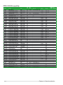
ASUS unique
features
ASUS Exclusive Features
- ASUS iCafe Memory Anti-theft
- ASUS AI Suite II
- AI Charger
- ASUS UEFI BIOS
ASUS Quiet Thermal Solution
- Stylish heatsink solution
- ASUS Q-Fan
ASUS EZ DIY
- ASUS CrashFree BIOS 3
- ASUS EZ Flash 2
- ASUS MyLogo 2™
Special features 100% All high-quality conductive polymer
Back Panel I/O
ports
1 x PS/2 mouse port
1 x PS/2 keyboard port
1 x D-Sub
1 x COM
1 x LAN (RJ-45) port
6 x USB 2.0 ports
3 x audio jacks
Internal I/O
connectors /
buttons / switches
2 x USB 2.0/1.1 connectors support additional 4 USB 2.0/1.1 ports
6 x SATA 3.0Gb/s connectors
1 x CPU fan connector
1 x Chassis fan connector
1 x Speaker connector
1 x High-denition front panel audio connector
1 x Chassis intrusion connector
1 x 10-pin System panel connector
1 x 24-pin EATX power connector
1 x 4-pin ATX 12V power connector
BIOS 64Mb Flash ROM, UEFI BIOS, PnP, DMI 2.0, WfM 2.0, ACPI 2.0a, SM
BIOS 2.6
Support DVD Drivers
ASUS Update
ASUS utilities
Anti-Virus software (OEM version)
Form Factor ATX form factor: 12.0 in x 8.1 in (30.5 cm x 20.6 cm)
A55-C specications summary

xi
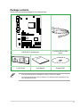
Package contents
Check your motherboard package for the following items.
A55-C
PCIEX16
PCIEX1_3
PCIEX1_2
PCIEX1_1
PCI2
PCI1
PCI3
AAFP
CPU_FAN
CHA_FAN
BATTERY
Super
I/O
AUDIO
ALC
887
EPU
KBMS
64Mb
BIOS
CLRTCCHASSIS
SPEAKER
USBPW7~10
KBPWR
USBPW1~6
AMD®
A55
RTL
8111F
DDR3 DIMM_A1 (64bit, 240-pin module)
DDR3 DIMM_B1 (64bit, 240-pin module)
LAN_USB12
USB56
USB34
SATA3G_2 SATA3G_4 SATA3G_6
SATA3G_1 SATA3G_3 SATA3G_5
SOCKET FM2
ATX12V
EATXPWR
VGA
COM
USB910 USB78 F_PANEL
ASUS A55-C motherboard 2 x Serial ATA 3.0 Gb/s
cables
User Guide
1 x I/O Shield User Manual Support DVD
• If any of the above items is damaged or missing, contact your retailer.
• The illustrated items above are for reference only. Actual product specications may
vary with different models.

xii

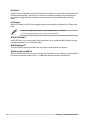
1.1 Special features
1.1.1 Product highlights
AMD® A-series accelerated processors with AMD® Radeon™ HD 7000 series
graphics
This motherboard supports AMD® A-series accelerated processors with AMD® Radeon™
HD 7000 series graphics. This revolutionary APU (Accelerated Processing Unit) combines
processing power and advanced DirectX 11 graphics in one small, energy-efcient design
that provides accelerated performance and an industry-leading visual experience. It features
Dual-channel DDR3 memory support and data transfer rates up to 5GT/s.
AMD® A55 FCH chipset
AMD® A55 FCH is designed to support up to 5GT/s interface speed and AMD® CrossFireX™
multi-GPU technology. It also supports 6 x SATA 3.0Gb/s ports.
100% All High-quality Conductive Polymer Capacitors
This motherboard uses all high-quality conductive polymer capacitors for durability, improved
lifespan, and enhanced thermal capacity.
1.1.2 ASUS Exclusive Features
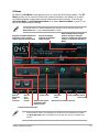
ASUS UEFI BIOS (EZ Mode)
ASUS UEFI BIOS, a UEFI compliant architecture, offers the rst mouse-controlled intuitive
graphical BIOS interface that goes beyond the traditional keyboard-only BIOS controls,
providing you with more exibility, convenience, and easier navigation than the traditional
BIOS versions. It offers you dual selectable modes and native support for hard drives larger
than 2.2 TB.
ASUS UEFI BIOS includes the following new features:
• F12 BIOS snapshot hotkey
• F3 Shortcut for most accessed information
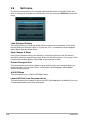
• ASUS DRAM SPD (Serial Presence Detect) information for detecting faulty DIMMs,
and helping with difcult POST situations.
Product introduction
1
ASUS A55-C 1-1

AI Suite II
ASUS AI Suite II integrates several ASUS utilities and allows you to launch and operate these
utilities simultaneously. It allows you to congure overclocking settings, adjust frequencies
and related voltage settings, remotely control the system via a mobile device, and other
tasks.
Ai Charger
ASUS Ai Charger is ASUS’ fast-charging software that supports the Apple iPod, iPhone, and
iPad.
• Check your USB mobile device if it fully supports the BC 1.1 standard.
• The actual charging speed may vary with your USB device.
ASUS EZ Flash 2
ASUS EZ Flash 2 is a user-friendly utility that allows you to update the BIOS without using a
bootable oppy disk or an OS-based utility.
ASUS MyLogo2™
Turn your favorite photos into 256-color boot logos to personalize your system.
ASUS CrashFree BIOS 3
ASUS CrashFree BIOS 3 is an auto-recovery tool that allows you to restore a corrupted BIOS
le using the bundled support DVD or a USB ash disk that contains the BIOS le.
Chapter 1: Product introduction
1-2

1.2 Before you proceed
Take note of the following precautions before you install motherboard components or change
any motherboard settings.
• Unplug the power cord from the wall socket before touching any component.
• Before handling components, use a grounded wrist strap or touch a safely grounded
object or a metal object, such as the power supply case, to avoid damaging them due
to static electricity.
• Hold components by the edges to avoid touching the ICs on them.
• Whenever you uninstall any component, place it on a grounded antistatic pad or in the
bag that came with the component.
• Before you install or remove any component, switch off the ATX power supply and
detach its power cord. Failure to do so may cause severe damage to the motherboard,
peripherals, or components.
ASUS A55-C 1-3

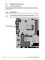
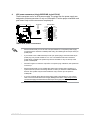
1.3 Motherboard overview
1.3.1 Placement direction
When installing the motherboard, ensure that you place it into the chassis in the correct
orientation. The edge with external ports goes to the rear part of the chassis as indicated in
the image below.
DO NOT overtighten the screws! Doing so can damage the motherboard.
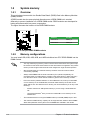
1.3.2 Screw holes
Place six screws into the holes indicated by circles to secure the motherboard to the chassis.
A55-C
Place this side towards
the rear of the chassis.
Chapter 1: Product introduction
1-4

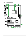
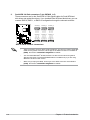
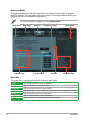
1.3.3 Motherboard layout
A55-C
PCIEX16
PCIEX1_3
PCIEX1_2
PCIEX1_1
PCI2
PCI1
PCI3
AAFP
CPU_FAN
CHA_FAN
BATTERY
Super
I/O
AUDIO
ALC
887
EPU
KBMS
64Mb
BIOS
CLRTCCHASSIS
SPEAKER
USBPW7~10
KBPWR
USBPW1~6
20.6cm(8.1in)
30.5cm(12.0in)
AMD®
A55
RTL
8111F
DDR3 DIMM_A1 (64bit, 240-pin module)
DDR3 DIMM_B1 (64bit, 240-pin module)
LAN_USB12
USB56
USB34
SATA3G_2 SATA3G_4 SATA3G_6
SATA3G_1 SATA3G_3 SATA3G_5
SOCKET FM2
ATX12V
EATXPWR
VGA
COM
USB910 USB78 F_PANEL
1 432 65 4
3
13 12 10 89112
7
ASUS A55-C 1-5

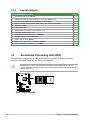
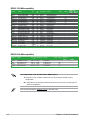
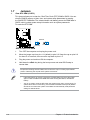
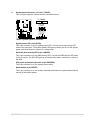
1.4 Accelerated Processing Unit (APU)
This motherboard comes with an FM2 socket designed for AMD® A-series accelerated
processors with AMD® Radeon™ HD 7000 series graphics.
Ensure that you use an APU designed for the FM2 socket. The APU ts in only one
correct orientation. DO NOT force the APU into the socket to prevent bending the pins and
damaging the APU!
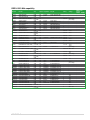
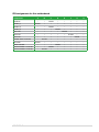
1.3.4 Layout contents
Connectors/Jumpers/Slots/LED Page
1. Keyboard power (3-pin KBPWR) 1-19
2. USB device wake-up (3-pin USBPW1~6, and 3-pin USBPW7~10) 1-19
3. ATX power connectors (24-pin EATXPWR, 4-pin ATX12V) 1-23
4. CPU and chassis fan connectors (4-pin CPU_FAN, and 3-pin CHA_FAN) 1-22
5. AMD FM2 socket 1-6
6. DDR3 DIMM slots 1-10
7. SATA 3.0Gb/s connectors (7-pin SATA3G_1~6) 1-24
8. Clear RTC RAM (3-pin CLRTC) 1-18
9. Chassis intrusion connector (4-pin CHASSIS) 1-26
10. Speaker connector (4-pin SPEAKER) 1-27
11. Front panel (10-pin F_PANEL) 1-25
12. USB 2.0 connectors (10-1 pin USB78, USB910) 1-27
13. Front panel audio connector (10-1 pin AAFP) 1-26
A55-C
A55-C CPU socket FM2
Chapter 1: Product introduction
1-6

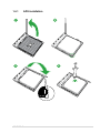
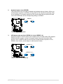
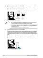
1.4.1 APU installation
1
43
2
ASUS A55-C 1-7

12
53 4
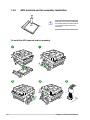
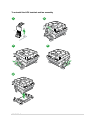
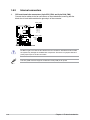
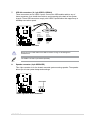
1.4.2 APU heatsink and fan assembly installation
Apply the Thermal Interface Material
to the APU heatsink and APU before
you install the heatsink and fan if
necessary.
To install the APU heatsink and fan assembly
Chapter 1: Product introduction
1-8
Page is loading ...
Page is loading ...
Page is loading ...
Page is loading ...
Page is loading ...
Page is loading ...
Page is loading ...
Page is loading ...
Page is loading ...
Page is loading ...
Page is loading ...
Page is loading ...
Page is loading ...
Page is loading ...
Page is loading ...
Page is loading ...
Page is loading ...
Page is loading ...
Page is loading ...
Page is loading ...
Page is loading ...
Page is loading ...
Page is loading ...
Page is loading ...
Page is loading ...
Page is loading ...
Page is loading ...
Page is loading ...
Page is loading ...
Page is loading ...
Page is loading ...
Page is loading ...
Page is loading ...
Page is loading ...
Page is loading ...
Page is loading ...
Page is loading ...
Page is loading ...
Page is loading ...
Page is loading ...
Page is loading ...
Page is loading ...
Page is loading ...
Page is loading ...
Page is loading ...
Page is loading ...
Page is loading ...
Page is loading ...
Page is loading ...
Page is loading ...
Page is loading ...
Page is loading ...
-
 1
1
-
 2
2
-
 3
3
-
 4
4
-
 5
5
-
 6
6
-
 7
7
-
 8
8
-
 9
9
-
 10
10
-
 11
11
-
 12
12
-
 13
13
-
 14
14
-
 15
15
-
 16
16
-
 17
17
-
 18
18
-
 19
19
-
 20
20
-
 21
21
-
 22
22
-
 23
23
-
 24
24
-
 25
25
-
 26
26
-
 27
27
-
 28
28
-
 29
29
-
 30
30
-
 31
31
-
 32
32
-
 33
33
-
 34
34
-
 35
35
-
 36
36
-
 37
37
-
 38
38
-
 39
39
-
 40
40
-
 41
41
-
 42
42
-
 43
43
-
 44
44
-
 45
45
-
 46
46
-
 47
47
-
 48
48
-
 49
49
-
 50
50
-
 51
51
-
 52
52
-
 53
53
-
 54
54
-
 55
55
-
 56
56
-
 57
57
-
 58
58
-
 59
59
-
 60
60
-
 61
61
-
 62
62
-
 63
63
-
 64
64
-
 65
65
-
 66
66
-
 67
67
-
 68
68
-
 69
69
-
 70
70
-
 71
71
-
 72
72


