Page is loading ...

OPERATIONS
MANUAL
QUAD OP
(OPERATING PLATFORM)
Document Number: 200-0013 Rev A

INTRODUCTION
FEATURES & CAPABILITIES
WIRING
HANG SPEAKERS
Configuring The System
Using The System
Final Wiring Checklist
table of contents
1
2
In the event of trouble, please contact:
Name:
Address:
Phone Number:
4
9
10
13
15

RISK OF ELECTRIC SHOCK- DO NOT OPEN THE UNIT.
THERE ARE NO SERVICABLE COMPONENTS INSIDE.
IMPORTANT SAFETY INSTRUCTIONS
1) Read these instructions.
2) Keep these instructions. Instructions are to be framed and placed adjacent to the control
unit for rady reference.
3) Heed all warnings.
4) Follow all instructions.
5) Do not use this apparatus near water.
6) Clean only with dry cloth.
7) Do not block any ventilation openings. Install in accordance with the manufacturer's
instructions.
8) Do not install near any heat sources such as radiators, heat registers, stoves, or other
apparatus (including amplifiers) that produce heat.
9) Do not defeat the safety purpose of the polarized or grounding-type plug. A polarized plug
has two blades with one wider than the other. A grounding type plug has two blades and a
third grounding prong. The wide blade or the third prong are provided for your safety. If the
provided plug does not fit into your outlet, consult an electrician for replacement of the
obsolete outlet.
10) Protect the power cord from being walked on or pinched particularly at plugs, convenience
receptacles, and the point where they exit from the apparatus.
11) Only use attachments/accessories specified by the manufacturer.
12) Use only with the cart, stand, tripod, bracket, or table specified by the manufacturer, or sold
with the apparatus. When a cart is used, use caution when moving the cart/apparatus
combination to avoid injury from tip-over.
13) Refer all servicing to qualified service personnel. Servicing is required when the apparatus
has been damaged in any way, such as power-supply cord or plug is damaged, liquid has
been spilled or objects have fallen into the apparatus, the apparatus has been exposed to
rain or moisture, does not operate normally, or has been dropped.
WARNING To reduce the risk of fire or electric shock, do not expose this apparatus to rain
or moisture and do not expose to dripping or splashing and no objects filled with liquids,
such as vases, shall be placed on the apparatus
14)

i.Net Quad OP
The primary sound source of the i.Net system is the Quad OP (Operating Platform) - A 1RU
rack mount unit that offers 4 OP's in 1, that produces, equalizes and distributes the sound.
Each Rack OP includes:
– Multiple, random sound masking sources, coupled with Lencore’s technology, produce a
sound quality that is random, making it exceptionally comfortable environment.
– Independent equalizers for unprecedented tuning where every channel of the system has a
separate and independent 1/3rd octave band equalizer or parametric equalizer.
– Sound frequencies and contour can be adjusted and set to any point on the acoustical
curve, from 20 Hz to 20 kHz, making i.Net the first networked sound masking system to
make fine-tuning the entire spectrum of sound possible.
–The multi-drop system and network is intelligent enough to bypass any failure in the system
to keep communicating throughout the entire network. Point-to-Point networks can not
achieve this level of connectivity and diagnostic control.
Groupings of sound sources and channels let you customize an almost limitless number of
zones for masking, paging and music, while maintaining the advantages of complete
networked operation and control.
Note: The i.Net Quad OP requires a Headend for music and paging applications.
1

Features and Capabilities:
The i.Net Quad OP includes many built-in features that used to require separately
purchased components.
• Data Entry Switches. The data entry switches allow the user to make a number of
adjustments to the system without using a computer.
• LCD display. The front panel display is used for displaying a variety of information.
• Four independent OP's in one unit for a total of 128 speakers on one unit
• Four IR input ports to control each OP separately with IR wall plates.
Installing the i.Net Quad OP:
The i.Net Quad OP is designed to be installed in a standard 19" rack.
Use four of the appropriate screws designed for the rack to mount to the OP.
Important: A 1RU of empty space is required immediately above the i.Net Quad OP for heat
dissipation. Failure to leave 1RU of empty space above the OP can result in the OP
overheating and eventual failure.
2

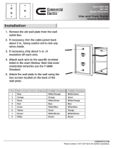
1. Data In/Out
Connect the Data out from the head-
end or previous OP to the OP Data In.
Connect the Data out to the next OP
Data In using RJ45 cables.
2. GND (Audio Common)
Connection for the ground wires to the
head end and next OP ground
connector.
3. IR
Connect IR wall units to these inputs
using RJ45 cables.
4. Channels
Connect external speakers to the
Channel's RJ45 connectors.
5. LEDs.
The PWR LED is on when power is
applied to the unit. The Fault LED is on
when the system is in a fault condition.
6. Data Entry Switches
The data entry switches are used to
make a number of adjustments to the
system without using a computer.
7. LCD Display
The LCD displays various diagnostic
messages and configuration
information about the system.
Front Panel
3

Wiring
4

Wiring
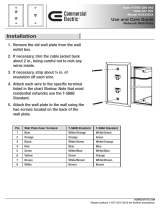
Power and Network connections:
1. Plug the unit into a standard 115VAC power outlet. The system will be usable in approximately 10 seconds.
Data, and Ground connections:
1. Wire the Data in cable to the previous OP or head-end Data out. Wire the Data Out cable to the next OP’s Data
In. On the last OP only, connect a data terminator to the OP's data out port
2. Wire a ground wire from the GND connector to the previous and next OP ground or to the headend common.
Audio Common (not building ground).
TO NEXT OP
DATA IN
TO OP “-“ OR HEAD-
END GROUND
IR connections::
1. Connect an IR unit to the IR port.
IR1 for U1 speakers.
IR2 for U2 speakers.
IR3 for U3 speakers.
IR4 for U4 speakers.
DATA IN
FROM HEAD-END
OR PREVIOUS OP
*Note: "U" refers to the unit number, not the OP number.
5

Wiring
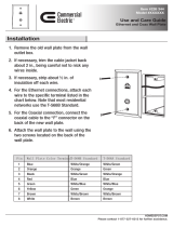
Speaker connections:
1. Connect the external speakers to the appropriate channel using cat 5 RJ45 cables.
Note: “U” refers to unit number not the OP number.
6

Wiring
Speaker Cable (RJ45) 568B
Speaker Cable connections are from the Quad OP to speakers and from speaker to speaker.
The pin out on the RJ45 is 568B.
The RJ45 connectors for the SPEAKER cables are non shielded.
1
5
2
6
3
7
4
8
PINS - 568 B
ORANGE|WHITE
ORANGE
GREEN|WHITE
BLUE
BLUE|WHITE
GREEN
BROWN|WHITE
BROWN
1
2
3
4
5
6
7
8
AUDIO (+)
AUDIO (+)
AUDIO (-)
AUDIO (-)
AUDIO (+)
AUDIO (+)
AUDIO (-)
AUDIO (-)
7

Wiring
Data Cable (RJ45) 568B
Data Cable connections are from the headend to the Quad OP and from i.Net OP to i.Net OP.
The pin out on the RJ45 is 568B.
The RJ45 connectors for the SPEAKER cables are non shielded.
1
5
2
6
3
7
4
8
PINS - 568 B
ORANGE|WHITE
ORANGE
GREEN|WHITE
BLUE
BLUE|WHITE
GREEN
BROWN|WHITE
BROWN
1
2
3
4
5
6
7
8
LON A | ILON® DATA NETWORK
LON B | ILON® DATA NETWORK
INITIALIZATION (SEQUENCER)
PAGE (+)
PAGE (-)
INITIALIZATION (SEQUENCER)
MUSIC (+)
MUSIC (-)
8

Hang Speakers
Data Cable (RJ45) 568B
1
2
3
4
Climb ladder and access the ceiling plenum
Hang speaker units in plenum area at marked locations using preferred hanging method
(powder action gun such as a Hilti-gun™ or drill and screw; check your local building codes
for allowable hanging methods and standards)
Drive a nail holding the clip with the speaker chain and speaker into ceiling
Pull and connect audio cables to speakers by channel
* keep speakers installed at very
consistent heights
6"-12"
NOTE: If installing Inline speakers, make sure the potentiometer on the bottom of the speaker is set to
the MAXIMUM (clockwise) setting.
9

Configuring the System
The system must be configured before any paging or music functions are used. The data entry
switches can be used to configure and adjust the system for many functions. System Manager must
be used to create any zones or to make more detailed adjustments such as equalizer settings. See
below for switches usage and the System Manager manual for using System Manager.
Front Panel Switches:
The switches allow the user to make a number of adjustments to the system without using a computer,
although, a computer and System Manager are still required for full control of all functions. A selection
can be made by continually pressing and releasing the switch.
The display shows OP operational data:
The upper left part of the display displays the function. The upper right displays the current option, within
that function. The lower left displays the Channel or Zone # that is related to the function. The lower right
displays the value associated with that channel or zone.
The FUNCTION button selects the function to be changed within each mode.
The OPT button selects the operation.
The up and down arrows increment and decrement the settings.
The SEL key is used to select operations.
Option
Function
Value
Selection
10

Operation Examples:
Masking Volume:
Press the FUNC button until “Mask Vol” is displayed.
OP/Channel:
Press the OPT button until “OP” is displayed.
Press the SEL button until the curser is on the value to change (OP number, channel letter, or
volume).
Use the up and down arrows to increment and decrement the selected value.
Zone:
Press the OPT button until “ZN” is displayed.
Press the SEL button until the curser is on the value to change (Zone number or volume).
Use the up and down arrows to increment and decrement the selected value.
Masking Contour:
Press the FUNC button until “Mask Cntr” is displayed.
OP/Channel:
Press the OPT button until “OP” is displayed.
Press the SEL button until the curser is on the value to change (OP number, channel letter, or
volume).
Use the up and down arrows to increment and decrement the selected value.
Zone:
Press the OPT button until “ZN” is displayed.
Press the SEL button until the curser is on the value to change (Zone number or volume).
Use the up and down arrows to increment and decrement the selected value.
Options and Functions:
Function Option Action
Masking Volume
OP/Channel Select
Zone Select
Masking Contour
OP/Channel Select
Zone Select
Mask Mute
OP/Channel Select
Zone Select
Music Volume
OP/Channel N/A
Zone N/A
Music Mute
OP/Channel N/A
Zone N/A
Paging Volume
OP/Channel N/A
Zone N/A
Paging Mute
OP/Channel N/A
Zone N/A
Voltages Voltage N/A
Neuron Version
N/A N/A
OP Status
Start OP #
N/A
OP # Up/Down
11

Masking Mute:
Press the FUNC button until “Mask Mute” is displayed.
OP/Channel:
Press the OPT button until “OP” is displayed.
Press the SEL button until the curser is on the value to change (OP number, channel letter, or
volume).
Use the up and down arrows to increment and decrement the selected value.
Zone:
Press the OPT button until “ZN” is displayed.
Press the SEL button until the curser is on the value to change (Zone number or volume).
Use the up and down arrows to increment and decrement the selected value.
Voltages:
Press the FUNC button until Voltages is displayed.
Press the OPT button to select the various voltages to display.
Note: Voltages cannot be changed, they can only be monitored.
PWR/SER
A green PWR (Power) LED indicates that the internal power supplies are operating.
The fault LED is on when the system is in a fault condition.
Neuron Version:
Press FUNC button until version neuron is displayed.
The display will show the current Neuron version.
Start OP #:
Press FUNC button until start OP # is displayed.
Use the op and down arrows to increment and decrement the OP number of unit 1.
Units 2-4 will automatically be numbered
Press SEL then cycle power to save values.
12

Using the System
Front Panel Indicators
Fault/Power
The FAULTLT LED indicates that the system is in a fault condition.
The POWER LED indicates that the internal power supplies are operating.
When power is first applied, the unit will begin a countdown from 20 seconds. The
display will show the countdown from 20 seconds to 1 second, then the status of the
four OP's will be displayed. If the OP powers-up properly, its number will be
displayed. If the OP is in a fault condition, its OP number will be "00".
13

Manual System Access & Tuning
A. i.Net system will automatically default to the acoustical handbook's
preferred curve.
B. Using a quality sound level meter to check the setting:
Set the entire environment to 47.5 dBA as measured four feet above
the finished floor. You can make adjustments using the System
Manager or hand-held remote.
C. For fine tuning
Leave all of the ceiling tiles that have an OP hanging above them exposed
so that incremental adjustments can be made with the hand-held remote
control prior to closing up the ceiling.
NOTE: This measurement should be accomplished in the evening
or after normal working hours and the ceiling tiles should be
90-95% installed for an accurate reading.
14

Final Wiring Checklist
q YES
BEFORE POWERING UP SYSTEM
Have you checked all home runs? Have you
checked all wiring between floors (risers)?
q YES
q YES
q YES
Are you sure all audio commons are properly tied between
power zones?
Have you made sure all Data and Audio wires are tested?
*Values are approx. based on 25’ cable run from OP to speaker and speaker to speaker.
TIP Check data wires by going to the i.Lon® and refreshing OP’s after
each OP is connected. This will help to eliminate large trouble shooting
issues at the end of the job.
TIP Check all speaker wires and speakers for good integrity, simply unplug the
1st speaker
wire from the OP and connect an RJ45 to a 8 conductor CAT5e wire on
one end and twist wire/pins 1,2 & 3 together and 4,5 & 6 together. This will give
you two leads + & -. Attach an OHM meter to the wire with the leads and attach
the other end into the first or last speaker in a run of speakers. If all is connected
correctly, you will approximate the following correct results on your OHM meter:
1 32.4
2 16.5
3 11.3
4 8.8
5 7.3
6 6.4
7 5.8
8 5.3
# of SPEAKERS OHMs*
Lencore offers a hand-held automatic speaker tester. Contact Lencore for details.
15

Lencore Acoustics Corp.
1 Crossways Park Drive West
Woodbury, NY 11797
516-682-9292
om
www.lencore.com
The information contained herein is proprietary to Lencore Acoustics Corp. and copyright protected. No part of this manual can
be copied, used or distributed without prior authorization from Lencore Acoustics Corp.
©
Copyright 2019
*For further technical support, please email support @lencore.com
/