Page is loading ...

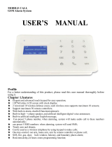
PiSector Professional
Wireless GSM Alarm System
User Manual (GSM-03)
Read manual fully before use.
PiSector Inc., USA, www.pisector.com

1.
WHAT'S IN THE BOX .................................................................. 4
2.
MAIN FEATURES ........................................................................ 5
3.
KNOW YOUR SYSTEM ............................................................... 6
4.
SYSTEM INITIALIZATION ........................................................... 9
5.
SYSTEM SETTING INSTRUCTIONS ........................................ 10
5.1.
E
NTERING
S
ETTING
M
ODE
..................................................... 10
5.2.
A
DDING
R
EMOTE
C
ONTROLLER
.............................................. 11
5.3.
D
ELETING
R
EMOTE
C
ONTROLLER
........................................... 13
5.4.
C
ODING
D
EFENSE
Z
ONE
........................................................ 14
5.5.
D
ELETING
D
EFENSE
Z
ONE
..................................................... 16
5.6.
S
ETTING
D
EFENSE
Z
ONE
P
LACES
........................................... 17
5.7.
S
ETTING
D
EFENSE
Z
ONE
M
ODES
........................................... 19
5.8.
S
ETTING
D
EFENSE
Z
ONE
S
IREN
............................................. 20
5.9.
A
LARM
D
ELAY
S
ETTING
......................................................... 21
5.10.
A
DDING
P
HONE
N
UMBER
....................................................... 22
5.11.
D
ELETING
P
HONE
N
UMBER
.................................................... 23
5.12.
A
DDING
SMS
C
ELL
P
HONE
N
UMBER
...................................... 24
5.13.
D
ELETING
SMS
C
ELL
P
HONE
N
UMBER
................................... 25
5.14.
V
OICE
R
ECORDING
............................................................... 26
5.15.
V
OICE
R
ECORDING
R
EPLAY
................................................... 27
5.16.
S
ETTING
S
YSTEM
D
ATE
......................................................... 28
5.17.
S
ETTING
S
YSTEM
T
IME
.......................................................... 29
5.18.
S
CHEDULING
T
IMELY
A
RM
...................................................... 30
5.19.
S
CHEDULING
T
IMELY
D
ISARM
................................................. 31
5.20.
W
IRELESS
S
IREN
C
ODING
...................................................... 32
5.21.
W
IRELESS
S
IREN
C
ODE
E
NCRYPTION
..................................... 33

3
5.22.
C
HANGE
O
PERATION
P
ASSWORD
............................................ 34
5.23.
C
HANGE
P
ROGRAM
P
ASSWORD
.............................................. 35
5.24.
S
ETTING
A
RM
D
ELAY
T
IME
..................................................... 36
5.25.
S
ETTING
A
LARM
(C
ALL
O
UT
)
D
ELAY
T
IME
................................ 37
5.26.
V
OICE
P
ROMPT
S
ETTING
....................................................... 38
5.27.
S
IREN
P
ROMPT
S
ETTING FOR
R
EMOTE
C
ONTROLLER
............... 39
5.28.
B
ACKLIGHT
S
ETTING
............................................................. 40
5.29.
S
IREN
S
ETTING IN
“E
MERGENCY
”
M
ODE
.................................. 41
5.30.
A
RM
/
D
ISARM
SMS
N
OTIFICATION
......................................... 42
5.31.
L
ANGUAGE
S
ETTING
.............................................................. 43
5.32.
F
ACTORY
R
ESET
................................................................... 44
5.33.
P
ASSWORD
R
ESET
................................................................ 45
6.
SYSTEM USAGE INSTRUCTIONS ........................................... 46
6.1.
O
UT
A
RM
............................................................................. 46
6.2.
H
OME
A
RM
........................................................................... 47
6.3.
D
ISARM
................................................................................ 48
6.4.
A
NSWER
A
LARM
C
ALL
........................................................... 49
6.5.
R
EMOTE
C
ONTROL
................................................................ 50
6.6.
E
MERGENCY
A
LARM
C
ALL
...................................................... 51
6.7.
U
SE AS
T
ELEPHONE
.............................................................. 52
6.8.
A
LARM
H
ISTORY
R
EVIEW
....................................................... 53
7.
TECHNICAL SPECIFICATIONS ................................................ 54
8.
CARE AND MAINTENANCE ..................................................... 55

4
1. What's In The Box
1 x Main Unit Panel
2 x Remote Controller
1 x Indoor Siren
1 x Passive IR Sensor
1 x Door Gap Sensor
1 x Power Adapter
1 x User Manual

5
2. Main Features
Quad-band worldwide cellular phone (900/1800/850/1900 MHz).
Elegant touch keypad with easy to use detailed menu system.
128×64 lattice LCD screen with clock display (English/Chinese)
4 wired and 10 wireless (433MHz) defense zones; each wireless
zone supports up to 10 sensors.
Support for up to 8 remote controllers.
Built-in loud speaker and intelligent voice announcer.
Auto-play 10-second pre-recorded voice message on alarm
(useful for giving address/GPS position to emergency services).
Up to 6 phone numbers to dial out on alarm.
Up to 3 SMS numbers: to send SMS to when alarm.
Remote control by phone to arm, disarm, or intercom (listen-in).
One-touch control: ARM (out arm), STAY (home arm) via touch
keypad or arm and disarm via remote controller or telephone.
4 Arm Modes: out arm, home arm, delay arm and timely arm for
scheduling arm / disarm times).
8 Defense Zone Places: SOS, fire, gas, door, hall, window,
balcony, and boundary.
4 Arm Delay Modes: Real-time (immediate), 01-99 second delay,
24 hours (always-armed even if system disarmed), Disable
Alarm calls have priority over all other calls if the device is busy.
Direct wireless coding of any additional wireless accessories.
Alarm History to store the last 30 alarm records.
Arm via the main unit panel, remote controller, or remote call by
phone.
SMS alert of power failure and recovery.
Built-in Lithium-Ion battery with automatic recharge.

6
3. Know Your System
1. LCD Screen: Resolution: 128×64; English and Chinese display.
2. LED Status Indicators
POWER: power and system activity indicator:
- fast flashing once per second: system is searching for GSM signal.
- slow flashing once per 3 seconds: system is in ready mode.
SET: is ON when the system enters setting mode.
SIGNAL: wireless signal indicator (used by wireless sensors).
ALARM: is ON if any sensor triggers or sets off an alarm.
3. Touch Keypad: Resistive Touch Panel requires gentle key pressing.
Do not press the keypad heavily as this may reduce its sensitivity.
ARM: press to enter OUT ARM status (gives you 40 seconds to
leave home before system is armed).
STAY: press to enter HOME ARM status (deactivates all sensors
with Home defense zone mode and activates all other sensors).
CALL: For making phone calls. Enter the number you want to call,
and then press this CALL button. Press again to end call (hang up).
SOS: press to raise an emergency alarm.

7
ESC: clears the input content or back to last operation.
ENTER: confirms current command or operation.
4. Wired Ports
1
SIREN+
Positive of siren (red cable)
2 SIREN- Negative of siren (black cable)
3
T_VCC
Reserved
port
4
CLK
Reserved
port
5 DATA Reserved port
6 T_GND Reserved port
7
GND
GND
8 Zone 1 Wired sensor 1: support both NO and NC
9
GND
GND
10 Zone 2 Wired sensor 2: support both NO and NC
11
GND
GND
12 Zone 3 Wired sensor 3: support both NO and NC
13
GND
GND
14 Zone 4 Wired sensor 4: support both NO and NC
15 GND GND

8
5. Internal Backup Battery Switch.
6. SIM Card Slot: Please pay attention to the direction arrow marked
on the slot: “LOCK” / “OPEN”. Do not insert or take out the SIM card
when the main unit panel is powered on.

9
4. System Initialization
Correct initialization of the main unit panel is important to its normal
working and lifespan.
1. Connect the wired accessories that you need.
2. Insert the SIM card.
3. Connect the power adapter. The main unit panel will start
self-inspection and the POWER indicator LED will flash once per
second. If this LED does not light on, you need to restart the main
unit panel. Please do it at least 10 seconds later as repeated power
on and off in short times will shorten the service life of the system.
4. The POWER indicator will flash once every 3 seconds after finding
GSM network successfully. This is the normal system state.
5. Turn on the internal backup battery switch on the back of the main
unit panel.
6. Check the GSM signal icon on the LCD screen. Signal less than 3
bars will affect normal performance. Please place the main unit
panel at a place with good GSM signal reception.

10
5. System Setting Instructions
5.1. Entering Setting Mode
All settings have to be done in the setting mode.
Use keys 2 / 8 / 4 / 6 as direction keys (up / down / left / right).
At the disarm state, input your 6-digit password (default: 888888), then
press ENTER. The main unit panel will sound a beep and the SET
indicator lights on. The screen will display Remote Control menu.
Fig 1: disarm status
Fig 2: please enter password
Fig 3: press ENTER to set

11
5.2. Adding Remote Controller
This system supports maximum 8 remote controllers ( 2 free remote
controllers come with package). All remote controllers have to be coded
with the main unit panel in order to perform correctly. Their code cannot
be empty or the same as those already saved in the main unit panel.
Method: enter remote controller setting menu, press “4” or “6” to choose
remote controller serial number, press “8” to find “Coding” and then
press ENTER to confirm. Trigger the remote controller you want to add,
the main unit panel will make two beeps after receiving it. And then
press ENTER to confirm. If the remote controller has been saved before,
after triggering it, the main unit panel will make four beeps and LCD
screen display “Error, Repeated code”.
Operation figures:
Fig 2: choose remote control serial
number and coding menu
Fig 1: enter remote control menu

12
Fig 4B: the main unit has the same code
with remote controller code
Fig 3: waiting to receive signal
Fig 4A: recognize successfully
Fig 5: press ENTER to save

13
5.3. Deleting Remote Controller
If the remote controller is lost or damaged, it must be deleted
immediately so no other person can control the main unit panel.
Method: enter remote controller setting menu, press “4” or “6” to choose
the remote controller you want to delete. Press “8” to find “Delete”, and
then press ENTER.
Operation figures:
Fig 1: enter remote controller setting
Fig 2: choose the controller you
want to delete
Fig 3: press ENTER to confirm

14
5.4. Coding Defense Zone
This alarm system supports 10 wireless defense zones, each of which
supports up to 10 wireless detectors. All sensors and sirens including
any extra ones not included in the standard package have to be coded
to the main unit panel in order to perform correctly. Their code cannot
be empty or the same as any of the saved codes in the main unit panel.
Method: enter defense zone setting menu, press “4” or “6” to choose
sensor, press “8” to find “Coding” and then press ENTER to confirm.
Trigger the sensor you want to add by hand, the unit will make two
beeps after receiving it. Press ENTER to confirm. If the sensor has
been saved before, after triggering it, the main unit panel will make four
beeps and LCD screen display “Error, Repeated code”.
Operation figures:
Fig 1: enter defense zone setting
Fig 2: choose zone number and press
ENTER

15
Fig 4B: the main unit has the same code
with sensor code
Fig 3: waiting signal from sensor
Fig 4A: recognize successfully
Fig 5: press ENTER to save

16
5.5. Deleting Defense Zone
The wireless detector cannot trigger the main unit panel after it is
deleted.
Method: enter defense zone setting menu, press “4” or “6” to choose
the sensor you want to delete. Press “8” to find “Delete”, and then press
ENTER. Operation figures:
Fig 1: enter defense zone setting
Fig 2: choose zone number
Fig 3: choose Delete and press ENTER

17
5.6. Setting Defense Zone Places
The location of defense zone can be set in the main unit panel, so that
the main unit panel can send detailed alarm messages. There are 8
locations for alarm: SOS, fire, gas, door, hall, window, balcony, and
boundary.
Please refer to “Chapter 6. Technical Parameters” for system default
settings.
Method: enter defense zone setting menu, press “4” or “6” to choose
the zone number, and then press “2” or “8” to enter zone place menu.
Press ENTER will shift the places.
Operation figures:
Fig 2: choose defense zone place
Fig 1: enter defense zone setting
Fig 3: press ENTER to confirm

18
The format of alarm SMS: [01~10] zone [place] alarm. For example,
you set the place of zone 4 as “Window”. The alarm SMS you receive is:
04 zone window alarm.
Fig 4: (this example)
Before setting, the alarm SMS for zone 1 is: 01 zone fire alarm;
After setting, it is: 01 zone gas alarm.

19
5.7. Setting Defense Zone Modes
There are different defense zone modes: out arm, home arm, alarm and
disarm mode. For example, if you need gas detectors working all the
time, then please set ARM, HOME, and DISARM as enabled.
Method: enter defense zone setting menu, press “2” or “8” to choose
HOME arm status (enable or disable), press ENTER to confirm. Setting
methods for OUT arm and DISARM are the same.
Operation figures:
Fig 1: enter defense zone setting
Fig 2: choose mode
Fig 3: press ENTER to confirm
Fig 4: (this example)
Before setting, zone 1 does not alarm in home arm status;
After setting, it will alarm when triggered in home arm status.

20
5.8. Setting Defense Zone Siren
The siren can be set on or off when there is an alarm for each defense
zone independently.
Method: enter defense zone setting, press “2” or “8” to choose siren
enable or disable, and then press ENTER to confirm.
Operation figures:
Fig 1: enter defense zone setting
Fig 2: choose siren status
Fig 3: press ENTER to confirm
Fig 4: (this example)
Before setting, the siren is on when zone 1 alarms;
After setting, siren will not sound when zone 1 alarms.
/