__p
53R-XS35V3-2801
XS35V3L Series Quick Guide【English】
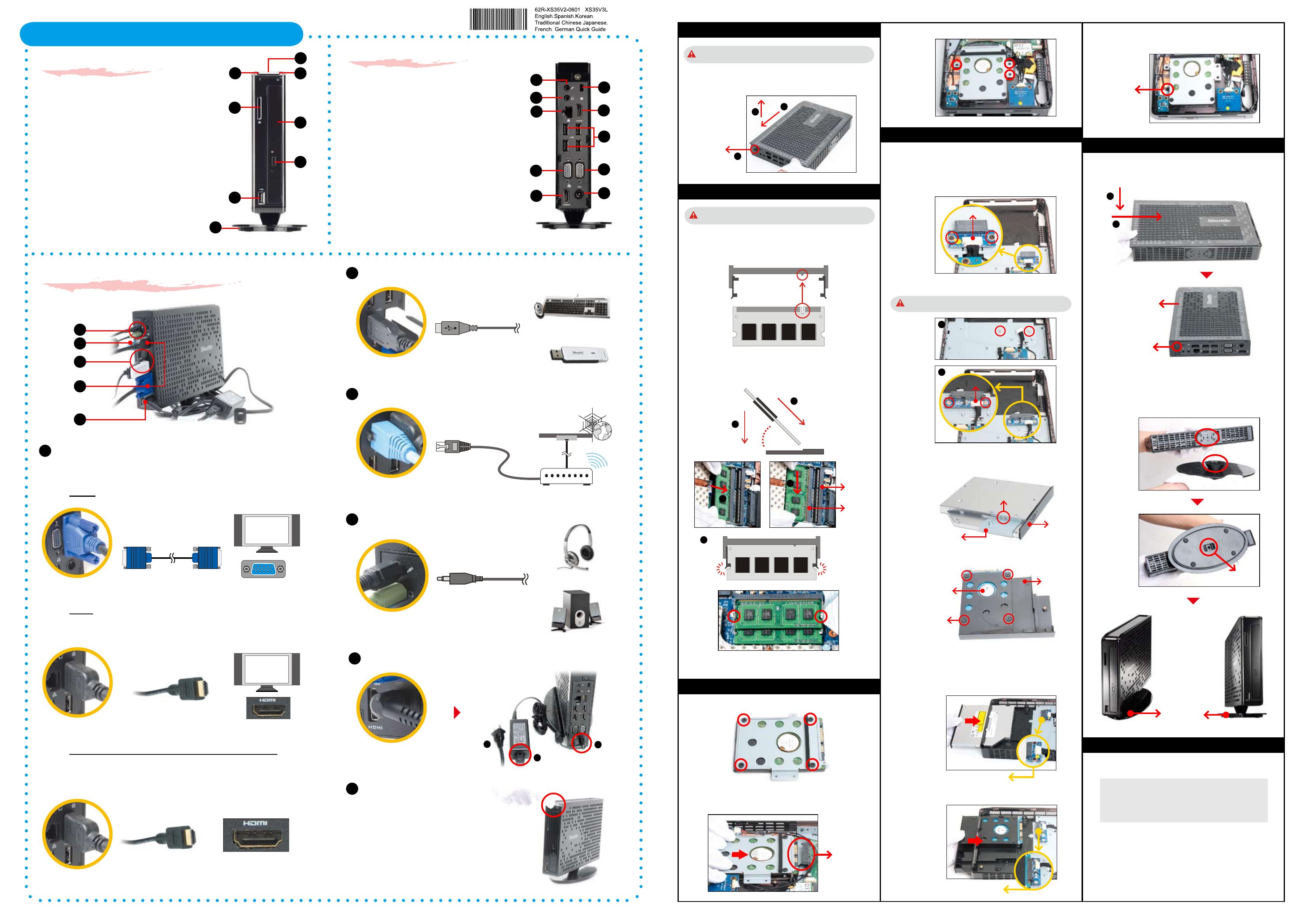
Front Panel
Back Panel
F1. Power Button
F2. Power Status LED
F3. HDD Status LED
F4. SD Card Reader
F5. ODD/ Second HDD (Optional)
F6. ODD Eject Button
F7. USB 2.0 Port
F8. Vertical Stand
B1. Microphone Jack
B2. Headphone/Line-out Jack
B3. LAN Port
B4. Kensington Lock
B5. HDMI Port (XS35V3L only)
B6. USB 2.0 Ports
B7. D-Sub (VGA) Port (XS35V3L only)
B8. Power Jack (DC-in)
B9. D-Sub (VGA) Port (XS35GS V3L only)
B10. HDMI Port (XS35GS V3L only)
F7
F4
F5
F6
F8
F1
F2
F3
A. Begin Installation
1. Unscrew one screw of the chassis cover.
2. Slide the cover backwards and upwards.
For safety reasons, please ensure that the power cord is disconnected
before opening the case.
B. Memory Module Installation
45-degree
angle
1. Locate the SODIMM slot on the mainboard.
2. Align the notch of the memory module with the one of the memory
slot.
3. Gently insert the module into the slot in a 45-degree angle.
4. Carefully push down the memory module until it snaps into the
locking mechanism.
C. HDD Installation
2
1
2. As shown, install the HDD & bracket in the chassis and push it
towards the direction as indicated by the red arrow to connect
the HDD connector.
D. ODD or Second HDD Installation
5. Turn your XPC upside down and tighten the ODD/HDD & bracket
with one screw.
1. Turn your XPC upside down and remove another cover.
2. As shown, install the ODD/HDD Adapter Card with two screws and
connect the cable to CN2/CN1.
For the ODD: install the ODD Adapter Card
If you are installing a second HDD, tighten the two nuts rst just
as shown.
3. Mount ODD/HDD into the bracket with screws.
Safety Information
Read the following precautions before setting up a XPC.
Laser compliance statement
The optical disc drive in this PC is a laser product.
The drive's classication label is located on the drive.
CLASS 1 LASER PRODUCT
CAUTION: INVISIBLE LASER RADIATION WHEN
OPEN.AVOID EXPOSURE TO BEAM.
CAUTION
Incorrectly replacing the battery may damage this co-mputer.
Replace only with the same or equivalent type recommended
by the manufacturer. Disposal of used batteries according to
the manufacturer's instructions.
3
Latch
Latch
SODIMM slot
4. As shown, install the ODD/HDD & bracket in the chassis and push
it towards the direction as indicated by the red arrow to connect the
ODD/HDD connector.
For a second HDD: install the HDD Adapter Card
CN2
HDD Connector
3
Screw
2
1
CN1
1. Mount HDD into the bracket with four screws.
two nuts
1
2
For the ODD
For a second HDD
For the ODD
For a second HDD
Screw
HDD
Bracket
Screw
ODD Connector
HDD Connector
ODD
Bracket
Screw
L
The product’s colour and specication will depend on the actual shipping product.
3. Tighten the HDD & bracket with three screws.
Connecting the System
5
Connecting Power
1
Connecting Monitor or LCD TVs
Digital and analog connections are available so the device can be
connected to computer monitors, at-panel displays, plasma or LCD TVs.
2
Connecting Keyboard/Mouse or USB Devices
3
Connecting LAN
4
Connecting Speakers and Microphonea
6
Powering on the system
Connecting HDTV or external amplier with HDMI output
Supports HDMI 1.3 standard with the ability to transmit audio and
video signal over the HDMI cable.
Analog: Connect this to your computer monitor or LCD TVs.
Digital:
Connect this to your HDMI-enabled computer monitor,
plasma or LCD TV.
D-Sub Port
D-Sub Cable
Display with D-Sub input
Display with HDMI input
HDMI Port
HDMI Cable
HDMI Cable
HDTV HDMI Connector
OR
Amplier HDMI Connector
HDMI Port
1
5
2
3
4
LAN Port
RJ45 Cable
Wall
Internet
DSL/Cable Modem
USB Ports
USB Devices
USB Keyboard/Mouse
Microphone,
Headphone/Line-out Jack
Microphone/Headphone
Speakers
Power Jack (DC-in)
1
2
3
1. Replace the cover and refasten one screw.
2. Tear o the double sided protective membrane.
E. Complete
Using the Vertical Stand
Install vertical stand and check that it is properly aligned, then
tighten securely with one screw.
Screw
Screw
Vertical Stand
Protective Membrane
1
2
5. Repeat the above steps to install additional memory modules,
if required.
B2
B1
B3
B10
B4
B8
B6
B9
B5
B7
If you install only one memory module in your system, install it in the
slot labeled "DIMM2".
1
2
DIMM2
DIMM1
