Simplicity 071036-00 User manual
- Category
- Power generators
- Type
- User manual

100/150/200 Amp Automatic
Transfer Switch
with Service Disconnect and
AC Control Module™
Operator’s Manual
Questions?
Help is just a moment away!
Call: Transfer Switch Helpline
800-743-4115 Monday - Friday 8:00 AM - 5:00 PM Central Time

2 BRIGGSandSTRATTON.COM
Thank you for your purchase of this Briggs & Stratton® automatic transfer switch. This product is designed for use with specific home
standby generators and may not function with generators or remote modules produced by other manufacturers. Seek a qualified electrical
professional to determine applicability of this equipment to equipment manufactured by others. When operated and maintained according to
the instructions in this manual, your system will provide many years of dependable service.
This manual contains safety information to make you aware of the hazards and risks associated with this system and how to avoid them.
We have made every effort to provide for a safe, streamlined and cost-effective installation. As each installation is unique, it is impossible
to know of and advise of all conceivable procedures and methods by which installation might be achieved. We do not know all possible
hazards and/or the results of each possible method or procedure. It is important that you read and understand these instructions thoroughly
before attempting to install or operate this equipment. Save these original instructions for future reference.
This transfer switch and optional remote modules require professional installation before use. Refer to the Installation Manual and the
installation instructions packaged with the remote modules for instructions on installation procedures. Only licensed electrical contractors
should install transfer switches and remote modules. Installations must strictly comply with all applicable federal, state and local codes,
standards and regulations. Your installer should follow the instructions completely.
Where to Find Us
You never have to look far to find Briggs & Stratton support and service for your system. Consult your Yellow Pages. There are many
authorized service dealers who provide quality service. You can also contact Technical Service by phone at 800-743-4115 between 8:00 AM
and 5:00 PM CT, or click on Find a Dealer at BRIGGSandSTRATTON.COM, which provides a list of authorized dealers.
Copyright © 2013. Briggs & Stratton Power Products Group, LLC
Milwaukee, WI, USA. All rights reserved.
Briggs & Stratton Power Products is a registered
trademark of Briggs & Stratton Corporation
Milwaukee, WI, USA

3
Table of Contents
Important Safety Instructions ...........................4
Installation ...........................................5
Home Owner Responsibilities .....................................5
Owner Orientation ...............................................5
Installing Dealer/Contractor Responsibilities .........................5
Equipment Description ...........................................6
Delivery Inspection ..............................................6
Controls .............................................7
Product Specfications ................................10

4 BRIGGSandSTRATTON.COM
Important Safety Instructions
SAVE THESE INSTRUCTIONS - This manual contains
important instructions that should be followed during
installation and maintenance of the equipment.
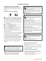
Safety Symbols and Meanings
The safety alert symbol indicates a potential personal injury
hazard. A signal word (DANGER, WARNING, or CAUTION) is used
with the alert symbol to designate a degree or level of hazard
seriousness. A safety symbol may be used to represent the type of
hazard. The signal word NOTICE is used to address practices not
related to personal injury.
DANGER indicates a hazard which, if not avoided, will result in
death or serious injury.
WARNING indicates a hazard which, if not avoided, could result
in death or serious injury.
CAUTION indicates a hazard which, if not avoided, could result
in minor or moderate injury.
NOTICE addresses practices not related to personal injury.
The manufacturer cannot possibly anticipate every possible
circumstance that might involve a hazard. The warnings in this
manual, and the tags and decals affixed to the unit are, therefore,
not all-inclusive. If you use a procedure, work method or operating
technique that the manufacturer does not specifically recommend,
you must satisfy yourself that it is safe for you and others. You
must also make sure that the procedure, work method or operating
technique that you choose does not render the equipment unsafe.
Electrical Shock Read Manual
Save These Instructions
NOTICE Only qualified electricians should attempt installation
of this equipment, which must strictly comply with applicable
codes, standards and regulations.
WARNING Certain components in this product and related
accessories contain chemicals known to the State of California
to cause cancer, birth defects, or other reproductive harm. Wash
hands after handling.
WARNING Shock Hazard. Installing low and high voltage
wire in same conduit could result in death, serious injury
and/or property damage.
• Do not run low and high voltage wire in the same conduit unless
the insulation rating on ALL wiring is rated for 600V. See NEC
for more information.
WARNING Shock Hazard. Failure to properly ground
equipment could cause electrocution resulting in death
or seriousinjury.
• Do not touch bare wires.
• Do not use equipment with worn, frayed, bare or otherwise
damaged wiring.
• Do not handle electrical cords while standing in water, while
barefoot, or while hands or feet are wet.
• If you must work around a unit while it is operating, stand on an
insulated dry surface to reduce shock hazard.
• Do not allow unqualified persons or children to operate or
service equipment.
• In case of an accident caused by electrical shock, immediately
shut down all sources of electrical power and contact local
authorities. Avoid direct contact with the victim.
WARNING Shock Hazard. Equipment contains high voltage
that could cause electrocution resulting in death or
seriousinjury.
• Do not operate this equipment imprudently, carelessly or neglect
its maintenance.
NOTICE Improper treatment of equipment could damage it and
shorten its life.
• Use equipment only for intended uses.
• If you have questions about intended use, ask dealer or contact
Briggs & Stratton Power Products.
• Do not expose equipment to excessive moisture, dust, dirt, or
corrosive vapors.
• Remain alert at all times while working on this equipment. Never
work on the equipment when you are physically or
mentally fatigued.
• If connected devices overheat, turn them off and turn off their
circuit breaker/fuse.

5
Installation
We sincerely appreciate your patronage and have made significant
effort to provide for a safe, streamlined and cost-effective
installation. Because each installation is unique, it is impossible
to know of and advise the trade of all conceivable procedures and
methods by which installation might be achieved. Neither could we
know of possible hazards and/or the results of each
method or procedure.
For these reasons, only current licensed electrical professionals
should attempt system installations. Installations must strictly
comply with all applicable codes, industry standards
and regulations.
Your equipment is supplied with this Operator’s Manual and an
Installation Manual. These are important documents and should be
retained by the owner after the installation has been completed.
Every effort has been made to make sure that the information
in this manual is both accurate and current. However, the
manufacturer reserves the right to change, alter or otherwise
improve the system at any time without prior notice.
NOTICE Before drilling conduit entry holes, or any other holes,
cover and protect the switch and electronics to prevent dirt and
metal fragments from entering the mechanical and electrical
components. Failure to do so may result in damage or malfunction
of the switch.
NOTICE Use a vacuum to clean any dirt or metal shavings inside
the transfer switch. Do not use a blower or compressed air to clean
the inside of the transfer switch because debris may become lodged
in the electrical and mechanical components causing damage or
malfunction.
Home Owner Responsibilities
To help you make informed choices and communicate effectively
with your installation contractor(s), read and understand Owner
Orientation before contracting or starting your
equipment installation.
To arrange for proper installation, contact the store at which you
purchased your equipment, your dealer, or your utility
power provider.
The equipment warranty is VOID unless the system is installed by
licensed electrical professionals.
Owner Orientation
The illustrations provided are for typical circumstances and are
meant to familiarize you with the installation options available with
your system.
Local codes, appearance, and distances are the factors that must
be considered when negotiating with an installation professional.
As the distance from the existing electrical service increases,
compensation in wiring materials must be allowed for. This is
necessary to comply with local codes and overcome electrical
voltage drops.
These factors will have a direct effect on the overall price of your
equipment installation.
Your installer must check local codes AND obtain permits before
installing the system.
• Readandfollowtheinstructionsgiveninthismanual.
• Followaregularscheduleincaringforandusingyour
equipment, as specified in this manual.
Installing Dealer/Contractor Responsibilities
• ReadandobservetheImportantSafetyInstructions.
• Readandfollowtheinstructionsgiveninthismanual.
• Theinstallermayneedtoprovideappropriateratedcontactors
based on loads to be controlled.
• Checkfederal,stateandlocalcodesandauthorityhaving
jurisdiction, for questions on installation.
• Ensuregeneratorisnotoverloadedwithselectedloads.
If you need more information about the transfer switch, call 800-
743-4115, between 8:00 AM and 5:00 PM CT.

6 BRIGGSandSTRATTON.COM
Equipment Description
The transfer switch is designed to transfer the selected loads found
in normal residential installations when used with the supervisory
contacts provided. The load is connected either to utility power
(normal) or home standby power (generator). The transfer switch
monitors utility and generator voltages and will automatically
connect to the appropriate source ofpower.
These switches make it easy for a licensed electrician to complete
a home standby installation. Service conduit and conductors can
be wired directly from the watt-hour meter to the transfer switch.
A separate disconnect and associated wiring is not required when
installed per applicable federal, state and local codes, standards and
regulations.
Major components of the transfer switch are a 2 pole utility
disconnect circuit breaker, a 2 pole generator disconnect circuit
breaker, a 2 pole double throw transfer switch, control circuit
board, fused utility terminals and interconnecting wiring. The
control board also has two inputs for current transformers that
sense generator current. These components are housed in a
NEMA 3R enclosure that is suitable for both indoor and outdoor
installations.
The transfer switch is solenoid-operated from utility or generator
inputs and contain suitable mechanical and electrical interlock
switches to eliminate the possibility of connecting the utility service
to the generator output. It has ratings capable of switching full
utility power into the residence. In addition, a manual override lever
is provided for the transfer function.
The control board has active circuits sensing utility and generator
voltages. It creates a signal for generator start-up, switch transfer
and retransfer when utility is restored. The control board also
contains red and green LED’s indicating the power sources available
and two relay operated contacts that provide supervisory control of
external loads.
Delivery Inspection
After opening the carton, carefully inspect the transfer
switch components for any damage that may have occurred
duringshipment.
If loss or damage is noted at time of delivery, have the person(s)
making delivery note all damage on the freight bill and affix his
signature under the consignor’s memo of loss or damage. If loss
or damage is noted after delivery, contact the carrier for claim
procedures. Missing or damaged parts are not warranted.
Shipment contents:
• Automatictransferswitch
• Installationandoperator’smanuals
• Currenttransformers(2)
To be supplied by installer:
• Connectingwireandconduit
• Variousspecialtytools/equipment

7
Controls
Other than a Manual Override lever, there are no operator controls
because this is an automatic transfer switch. The manual override
is to be used only by licensed professionals. Information on handle
use can be obtained by calling Technical Service at 800-743-4115.
Operation
To select automatic transfer operation, do the following:
1. In transfer switch, set utility disconnect circuit breaker
to “ON” position.
2. In transfer switch, set generator disconnect circuit
breaker to “ON” position.
3. Install 15 Amp fuse in generator’s control panel.
4. Set generator’s circuit breaker to “ON” position.
5. Set generator’s system switch to “AUTO” position.
The system will now be in automatic operation mode.
When the generator is providing power to the transfer
switch, the transfer switch control board is constantly
monitoring generator power. If the air conditioner is called
to run, and there is sufficient generator power available,
the controller will close contacts “A-A” to air conditioner
contactor. Contacts “B B” will open before contacts A-A
close. If loads are too great for the generator, contacts A-A
and/or B-B will open. When air conditioning is not needed,
A-A will open. If enough power is available, B-B will close.
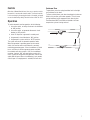
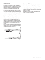
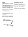
Enclosure Door
To open door, press the spring-load door lock to the right
and pull down on the door.
To close and latch door, push door closed against enclosure.
While in this position, push door upwards. This will cause
spring-load door lock to engage and latch door in place.
Enclosure door MUST be closed and latched at all times
except when system is being serviced.

8 BRIGGSandSTRATTON.COM
Testing the Automatic Transfer Switch
Turn the utility disconnect circuit breaker feeding the
transfer switch contactor to the “OFF” position. The
system’s automatic sequence will initiate. To return to utility
power, turn the utility disconnect circuit breaker to the
“ON”position.
Utility Fail
The generator senses when utility voltage is below
70percent of nominal. Engine start sequence is initiated
after 6 second time delay.
Engine Warm-Up
Time delay to allow for engine warm-up before transfer. Use
jumper on transfer switch control board to select delay of
20seconds or 50seconds.
Transfer
Transfer from utility to generator supply occurs after voltage
is above set levels. Minimum engine run time is 5 minutes
after transfer.
Utility Pickup
Voltage pickup level is 80 percent of nominal voltage.
Retransfer
Retransfer from generator to utility power is approximately
10 seconds after utility voltage supply is above pickup level
and minimum run time is completed.
Engine Cool Down
Engine will run for 60 seconds after retransfer.
Maintenance
The transfer switch is designed to be maintenance free under
normal usage. However, inspection and maintenance checks
should be made on a regular basis. Maintenance will consist
mainly of keeping the transfer switch clean.
Visual inspections should be done at least once a month.
Access to transfer switch must not be obstructed. Keep
3feet (92 cm) clearance around transfer switch. Check
for an accumulation of dirt, moisture and/or corrosion
on and around the enclosure, loose parts/hardware,
cracks and/or discoloration to insulation, and damaged or
discoloredcomponents.
Exercise the transfer switch at least once every three months
as described in Testing the Automatic Transfer Switch unless
a power outage occurs and home generator system has gone
through an automatic sequence. Allow generator to run for at
least 30 minutes.
Contact a licensed electrical professional to inspect and clean
the inside of the enclosure and other components of your
home generator system at least once a year.
When Calling for Assistance
You must have the Model Number and Serial Number from
the unit ID label at hand if it is necessary to contact a local
service center regarding service or repair of this unit. Obtain
this information from the unit ID label located on or inside
the enclosure.
To contact Briggs & Stratton call 800-743-4115, between
8:00 AM and 5:00 PM CT.
Installation Inspection
Before placing the system into service, inspect the entire
installation carefully.
WARNING Shock Hazard. Equipment contains high voltage
that could cause electrocution resulting in death or
serious injury.
• Testing must only be performed by qualified personnel.
• Do not operate this equipment imprudently, carelessly or neglect
its maintenance.

9
ABOUT YOUR WARRANTY
We welcome warranty repair and apologize to you for being inconvenienced. Any Authorized Service Dealer may perform warranty repairs. Most warranty
repairs are handled routinely, but sometimes requests for warranty service may not be appropriate. For example, warranty service would not apply if
equipment damage occurred because of misuse, lack of routine maintenance, shipping, handling, warehousing or improper installation. Similarly, the warranty
is void if the manufacturing date or the serial number on the equipment has been removed or the equipment has been altered or modified. During the warranty
period, the Authorized Service Dealer, at its option, will repair or replace any part that, upon examination, is found to be defective under normal use and
service. This warranty will not cover the following repairs and equipment:
• Normal Wear: Outdoor Power Equipment, like all mechanical devices, needs periodic parts and service to perform well. This warranty does not cover
repair when normal use has exhausted the life of a part or the equipment.
• Installation and Maintenance: This warranty does not apply to equipment or parts that have been subjected to improper or unauthorized installation
or alteration and modification, misuse, negligence, accident, overloading, improper maintenance, repair or storage so as, in our judgment, to adversely
affect its performance and reliability. This warranty also does not cover normal maintenance such as adjustments, cleaning and fuse replacement.
• Other Exclusions: This warranty excludes wear items or damage or malfunctions resulting from accidents, abuse, modifications, alterations, or
improper servicing. Accessory parts are excluded from the product warranty. This warranty excludes failures due to acts of God and other force
majeure events beyond the manufacturers control. Also excluded is used, reconditioned, and demonstration equipment. 198180E, Rev. C, 12/31/2006
BRIGGS & STRATTON POWER PRODUCTS GROUP, LLC
MILWAUKEE, WI, USA
BRIGGS & STRATTON POWER PRODUCTS GROUP, LLC TRANSFER SWITCH OWNER WARRANTY POLICY
LIMITED WARRANTY
Briggs & Stratton Power Products Group, LLC will repair or replace, free of charge, any part(s) of the equipment that is defective in material or
workmanship or both. Transportation charges on product submitted for repair or replacement under this warranty must be borne by purchaser. This
warranty is effective for the time periods and subject to the conditions stated below. For warranty service, find the nearest Authorized Service Dealer in
our dealer locator map at BRIGGSandSTRATTON.COM.
THERE IS NO OTHER EXPRESS WARRANTY. IMPLIED WARRANTIES, INCLUDING THOSE OF MERCHANTABILITY AND FITNESS FOR A
PARTICULAR PURPOSE, ARE LIMITED TO ONE YEAR FROM PURCHASE, OR TO THE EXTENT PERMITTED BY LAW. ANY AND ALL IMPLIED
WARRANTIES ARE EXCLUDED. LIABILITY FOR INCIDENTAL OR CONSEQUENTIAL DAMAGES ARE EXCLUDED TO THE EXTENT EXCLUSION IS
PERMITTED BY LAW. Some states or countries do not allow limitations on how long an implied warranty lasts, and some states or countries do not allow
the exclusion or limitation of incidental or consequential damages, so the above limitation and exclusion may not apply to you. This warranty gives you
specific legal rights and you may also have other rights which vary from state to state or country to country.
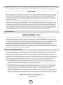
Effective November 1, 2005 replaces all undated Warranties and all Warranties dated before November 1, 2005
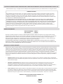
The warranty period begins on the date of purchase by the first retail consumer or commercial end user, and continues for the period of time stated in the
table above. “Consumer use” means personal residential household use by a retail consumer. “Commercial use” means all other uses, including use for
commercial, income producing or rental purposes. Once equipment has experienced commercial use, it shall thereafter be considered as commercial use for
purposes of this warranty. Equipment used for prime power in place of utility are not applicable to this warranty.
NO WARRANTY REGISTRATION IS NECESSARY TO OBTAIN WARRANTY ON BRIGGS & STRATTON PRODUCTS. SAVE YOUR PROOF OF
PURCHASE RECEIPT. IF YOU DO NOT PROVIDE PROOF OF THE INITIAL PURCHASE DATE AT THE TIME WARRANTY SERVICE IS REQUESTED,
THE MANUFACTURING DATE OF THE PRODUCT WILL BE USED TO DETERMINE THE WARRANTY PERIOD.
3 years
None
Consumer Use
Commercial Use
WARRANTY PERIOD

10 BRIGGSandSTRATTON.COM
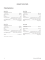
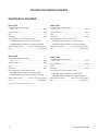
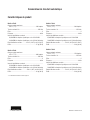
Automatic Transfer Switch
Product Specfications
Model 071045
Rated Maximum Load Current
a 25°C (77°F)* ..............................................................100 Amps
Rated AC Voltage. ..............................................................250 Volts
Poles ............................................................................................... 2
Frequency ................................................................................60 Hz
Fault Current Rating ..........22,000 RMS Symmetrical Amperes on Utility Side
................................. 10,000 RMS Symmetrical Amperes on Generator Side
Normal Operating Range ...............-28.8°C (-20°F) to 40°C (104°F)
Weight ........................................................................27 kg (59 lbs)
Model 071046
Rated Maximum Load Current
a 25°C (77°F)* ..............................................................200 Amps
Rated AC Voltage. ..............................................................250 Volts
Poles ............................................................................................... 2
Frequency ................................................................................60 Hz
Fault Current Rating ..........
25,000 RMS Symmetrical Amperes on Utility Side
................................. 10,000 RMS Symmetrical Amperes on Generator Side
Normal Operating Range ...............-28.8°C (-20°F) to 40°C (104°F)
Weight ........................................................................28 kg (63 lbs)
This transfer switch is a UL Listed device.
Model 071044
Rated Maximum Load Current
a 25°C (77°F)* ..............................................................200 Amps
Rated AC Voltage. ..............................................................250 Volts
Poles ............................................................................................... 2
Frequency ................................................................................60 Hz
Fault Current Rating ..........25,000 RMS Symmetrical Amperes on Utility Side
................................. 10,000 RMS Symmetrical Amperes on Generator Side
Normal Operating Range ...............-28.8°C (-20°F) to 40°C (104°F)
Weight ........................................................................28 kg (63 lbs)
Model 071069
Rated Maximum Load Current
a 25°C (77°F)*...............................................................150 Amps
Rated AC Voltage. ..............................................................250 Volts
Poles ............................................................................................... 2
Frequency ................................................................................60 Hz
Fault Current Rating ..........
25,000 RMS Symmetrical Amperes on Utility Side
................................. 10,000 RMS Symmetrical Amperes on Generator Side
Normal Operating Range ...............-28.8°C (-20°F) to 40°C (104°F)
Weight ........................................................................28 kg (63 lbs)
Page is loading ...
Page is loading ...
Page is loading ...
Page is loading ...
Page is loading ...
Page is loading ...
Page is loading ...
Page is loading ...
Page is loading ...
Page is loading ...
Page is loading ...
Page is loading ...
Page is loading ...
Page is loading ...
Page is loading ...
Page is loading ...
Page is loading ...
Page is loading ...
Page is loading ...
Page is loading ...
Page is loading ...
Page is loading ...
-
 1
1
-
 2
2
-
 3
3
-
 4
4
-
 5
5
-
 6
6
-
 7
7
-
 8
8
-
 9
9
-
 10
10
-
 11
11
-
 12
12
-
 13
13
-
 14
14
-
 15
15
-
 16
16
-
 17
17
-
 18
18
-
 19
19
-
 20
20
-
 21
21
-
 22
22
-
 23
23
-
 24
24
-
 25
25
-
 26
26
-
 27
27
-
 28
28
-
 29
29
-
 30
30
-
 31
31
-
 32
32


Simplicity 071036-00 User manual
- Category
- Power generators
- Type
- User manual
Ask a question and I''ll find the answer in the document
Finding information in a document is now easier with AI
in other languages
- français: Simplicity 071036-00 Manuel utilisateur
- español: Simplicity 071036-00 Manual de usuario
Related papers
-
Simplicity 040344-00 User manual
-
Simplicity 071058-00 User manual
-
-
Simplicity 040385-01 User manual
-
-
-
Simplicity 071060-00 User manual
-
-
-
Other documents
-
General Electric 200 AMP AUTOMATIC TRANSFER SWITCH Owner's manual
-
Briggs & Stratton 071057 Installation guide
-
-
Briggs & Stratton Switch 71019 User manual
-
-
-
-
-
-
Promate Symphony User guide