
Operator’s Manual
Notice d'emploi
Mobile Generator
Groupe électrogène mobile
G70, G100
G130, G150
Type G70, G100, G130, G150
Document
5100027140
Date 0217
Revision 02
Language
EN
-FR
5100027140

Copyright notice
© Copyright 2017 by Wacker Neuson Production Americas LLC
All rights, including copying and distribution rights, are reserved.
This publication may be photocopied by the original purchaser of the
machine. Any other type of reproduction is prohibited without express
written permission from Wacker Neuson Production Americas LLC.
Any type of reproduction or distribution not authorized by Wacker
Neuson Production Americas LLC represents an infringement of valid
copyrights. Violators will be prosecuted.
Trademarks
All trademarks referenced in this manual are the property of their
respective owners.
Manufacturer
Wacker Neuson Production Americas LLC
N92W15000 Anthony Avenue
Menomonee Falls, WI 53051 U.S.A.
Tel: (262) 255-0500 · Fax: (262) 255-0550 · Tel: (800) 770-0957
www.wackerneuson.com
Original instructions
This Operator’s Manual presents the original instructions. The original
language of this Operator’s Manual is American English.

wc_tx004281gb_FM10.fm
3
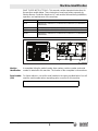
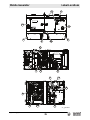
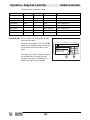
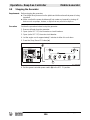
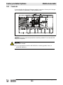
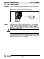
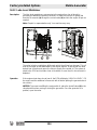
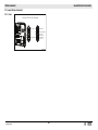
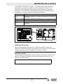
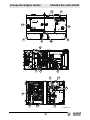
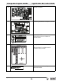
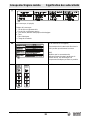
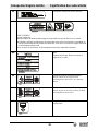
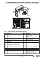
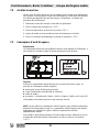
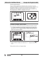
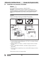
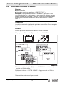
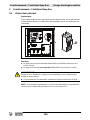
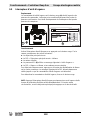
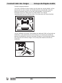
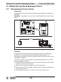
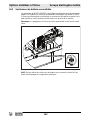
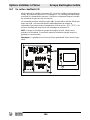
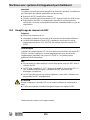
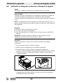
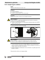
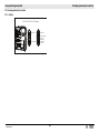
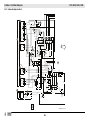
Machine Identification
SAVE THESE INSTRUCTIONS—This manual contains important instructions for
the machine models below. These instructions have been written expressly by
Wacker Neuson Production Americas LLC and must be followed during installation,
operation, and maintenance of the machines.
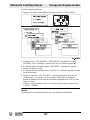
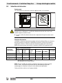
Machine
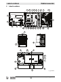
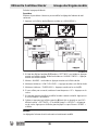
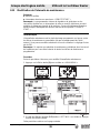
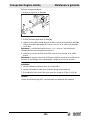
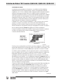
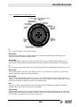
identification
A nameplate listing the model number, item number, revision number, and serial
number is attached to this machine. The location of the nameplate is shown above.
Serial number
(S/N)
For future reference, record the serial number in the space provided below. You will
need the serial number when requesting parts or service for this machine.
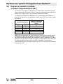
Machine Item Number
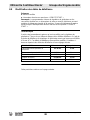
G70 5200023226, 5200023227, 5200023228, 5200023974, 5100018635,
5100021959
G100 5100033310, 5100033311, 5100033312
G130 5200023232, 5200023233, 5200023234, 5100018637, 5100022091
G150 5200022870, 5200023235, 5200023236, 5200023237, 5100018638,
5100022092
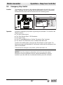
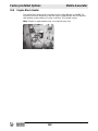
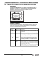
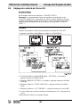
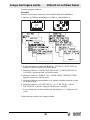
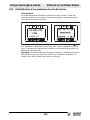
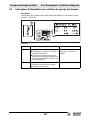
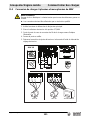
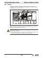
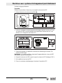
wc_gr013470
R
Serial Number
159047
hz
215429
For electrical
equipment only.
Pour material
electrique
seulement.
amb.temp.
Rev.
Type/Model
Item Number
rpm
lbs
PRIME RATING
kW/
kVA
V
A
kg
MADE
IN USA
Serial Number:

4 wc_tx004282gb_FM10.fm
Mobile Generator
Foreword
Foreword
Machine
documentation
■ From this point forward in this documentation, Wacker Neuson Production
Americas LLC will be referred to as Wacker Neuson.
■ Keep a copy of the Operator’s Manual with the machine at all times.
■ For spare parts information, please see your Wacker Neuson Dealer, or visit the
Wacker Neuson website at http://www.wackerneuson.com/.
■ When ordering parts or requesting service information, be prepared to provide
the machine model number, item number, revision number, and serial number.
Expectations
for
information in
this manual
■ This manual provides information and procedures to safely operate and
maintain the above Wacker Neuson model(s). For your own safety and to
reduce the risk of injury, carefully read, understand, and observe all instructions
described in this manual.
■ Wacker Neuson expressly reserves the right to make technical modifications,
even without notice, which improve the performance or safety standards of its
machines.
■ The information contained in this manual is based on machines manufactured
up until the time of publication. Wacker Neuson reserves the right to change any
portion of this information without notice.
■ The illustrations, parts, and procedures in this manual refer to Wacker Neuson
factory-installed components. Your machine may vary depending on the
requirements of your specific region.
CALIFORNIA
Proposition
65 Warning
Combustion exhaust, some of its constituents, and certain vehicle components
contain or emit chemicals known to the State of California to cause cancer and
birth defects or other reproductive harm.
Laws
pertaining to
spark
arresters
NOTICE: State Health Safety Codes and Public Resources Codes specify that in
certain locations spark arresters be used on internal combustion engines that use
hydrocarbon fuels. A spark arrester is a device designed to prevent accidental
discharge of sparks or flames from the engine exhaust. Spark arresters are
qualified and rated by the United States Forest Service for this purpose. In order to
comply with local laws regarding spark arresters, consult the engine distributor or
the local Health and Safety Administrator.

wc_tx004282gb_FM10.fm 5
Mobile Generator
Foreword
Manufacturer’s
approval
This manual contains references to approved parts, attachments, and
modifications. The following definitions apply:
■ Approved parts or attachments are those either manufactured or provided by
Wacker Neuson.
■ Approved modifications are those performed by an authorized Wacker
Neuson service center according to written instructions published by Wacker
Neuson.
■ Unapproved parts, attachments, and modifications are those that do not
meet the approved criteria.
Unapproved parts, attachments, or modifications may have the following
consequences:
■ Serious injury hazards to the operator and persons in the work area
■ Permanent damage to the machine which will not be covered under warranty
Contact your Wacker Neuson dealer immediately if you have questions about
approved or unapproved parts, attachments, or modifications.

6 wc_tx004282gb_FM10.fm
Mobile Generator
Foreword
Notes

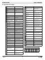
Table of Contents
G70 / G100 / G130 / G150
wc_bo5100027027_02_FM10T
7
Foreword 4
1 Safety Information 13
1.1 Signal Words Used in this Manual ..................................................... 13
1.2 Machine Description and Intended Use ............................................. 14
1.3 Safety Guidelines for Operating the Machine ..................................... 15
1.4 Service Safety .................................................................................... 17
1.5 Operator Safety while Using Internal Combustion Engines ............... 19
1.6 Safety Guidelines for Mobile Generators ........................................... 20
1.7 Safety Guidelines for Towing the Machine ......................................... 22
1.8 Safety Guidelines for Lifting the Machine ........................................... 23
1.9 Reporting Safety Defects ................................................................... 23
2 Label Locations 24
3 Label Meanings 26
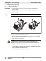
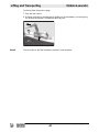
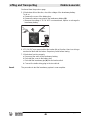
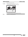
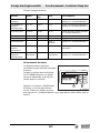
4 Lifting and Transporting 38
4.1 Lifting the Machine ............................................................................. 38
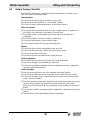
4.2 Before Towing Checklist ..................................................................... 39
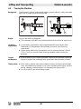
4.3 Towing the Machine ........................................................................... 40
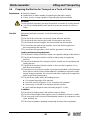
4.4 Preparing the Machine for Transport on a Truck or Trailer ................ 41
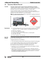
4.5 Hazardous Materials Placards ........................................................... 42
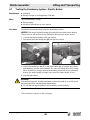
4.6 Testing the Breakaway System—Hydraulic Surge Brakes ................. 43
4.7 Testing the Breakaway System—Electric Brakes .............................. 45
5 Machine Setup 47
5.1 Preparing the Machine for First Use ................................................... 47
5.2 Positioning the Machine ..................................................................... 48
5.3 Grounding the Generator ................................................................... 50
5.4 Recommended Fuel ........................................................................... 51
5.5 Refueling the Machine—Basler Controller ......................................... 52
5.6 Refueling the Machine—Deep Sea Controller ................................... 53
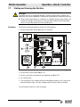
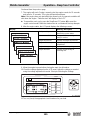
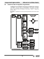
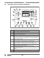
6 Operation, Control, and Component Locations 54
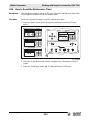
6.1 Control and Component Locations ..................................................... 54
6.2 Control Panel Components ................................................................ 55

Table of Contents
G70 / G100 / G130 / G150
wc_bo5100027027_02_FM10TOC.fm
8
7 Operation—Basler Controller 56
7.1 Engine Start Switch .............................................................................56
7.2 Genset Pre-Alarms and Alarms (Shut-Down Conditions) ...................57
7.3 Overcurrent Condition .........................................................................58
7.4 Using the Lugs and the Convenience Receptacles .............................59
7.5 Selecting the Voltage ..........................................................................60
7.6 Before Starting the Machine ................................................................62
7.7 Starting and Running the Machine ......................................................63
7.8 Stopping the Machine ..........................................................................66
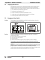
7.9 Emergency Stop Switch ......................................................................66
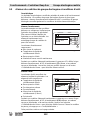
7.10 LCD Panel: Monitoring Machine Operation .........................................67
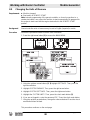
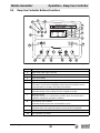
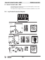
8 Working with Basler Controller 69
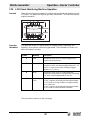
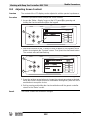
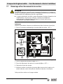
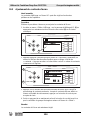
8.1 How to Use the Genset Controller LCD and Keypad ..........................69
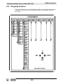
8.2 Menu Diagram of the Genset Controller ..............................................70
8.3 Menu Diagram Components ...............................................................71
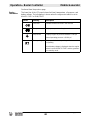
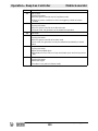
8.4 Using the Metering and Settings Menus .............................................72
8.5 Logging in to the Genset Controller by Entering the Password ...........73
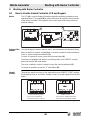
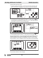
8.6 Adjusting the LCD Screen Contrast ....................................................76
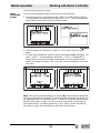
8.7 Changing the Time/Date Settings .......................................................77
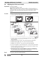
8.8 Changing the Sender Fail Time Delays ...............................................78
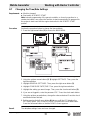
8.9 Changing the Units of Measure ...........................................................80
8.10 Changing the Low Fuel Pre-Alarm Setting ..........................................82
8.11 Changing or Disabling the Low Fuel Alarm Setting .............................84
8.12 Changing the Cooldown Time Setting .................................................86
8.13 Changing the Maintenance Interval .....................................................88
8.14 Resetting the Maintenance Interval Pre-Alarm ....................................90
8.15 Resetting a Loss of Voltage Pre-Alarm ...............................................92
8.16 Accessing and Using the Event Log ....................................................93
9 Operation—Deep Sea Controller 95
9.1 Main Circuit Breaker ............................................................................95
9.2 Genset Controller Power Switch .........................................................96
9.3 Selecting the Voltage ..........................................................................97
9.4 Deep Sea Controller Buttons/Functions ..............................................99
9.5 Genset Controller Alarms and Shut-Down Conditions ......................101
9.6 Before Starting the Machine ..............................................................103
9.7 Starting and Running the Generator .................................................104
9.8 Stopping the Generator .....................................................................106

Table of Contents
G70 / G100 / G130 / G150
wc_bo5100027027_02_FM10T
9
9.9 Emergency Stop Switch ................................................................... 107
9.10 Engine and Generator Monitoring .................................................... 108
10 Working with Deep Sea Controller: DSE 7310 109
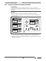
10.1 Introduction ....................................................................................... 109
10.2 Navigating the Menus ....................................................................... 110
10.3 Adjusting Screen Contrast ................................................................ 112
10.4 How to Reset the Maintenance Timer .............................................. 113
11 How to Connect Loads—480V 114
11.1 Lug Terminal Connection Diagrams ................................................. 114
11.2 Best Practices for Balancing Loads .................................................. 115
11.3 Connecting 480V, 3-Phase and Single-Phase Loads ...................... 118
11.4 Connecting a 240V 3Ø Load and a 240V 1Ø Load .......................... 119
11.5 Connecting 240V and 120V Single-Phase Loads ............................ 120
11.6 Connecting a 208V 3Ø Load and Multiple 120V 1Ø Loads .............. 121
11.7 Connecting a 220–240V 3Ø Load and Multiple 127–133V
1Ø Loads .......................................................................................... 122
12 Using Remote Start Capabilities 123
12.1 Remote Run Terminal Block ............................................................ 123
12.2 Remote Transfer Switch ................................................................... 124
12.3 Preparing for Automatic/Remote Start-Up—Basler .......................... 125
12.4 Preparing for Automatic/Remote Start-Up—Deep Sea .................... 126
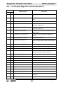
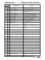
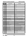
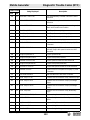
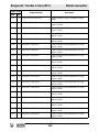
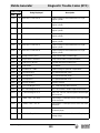
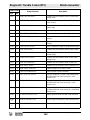
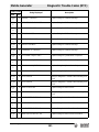
13 Diagnostic Trouble Codes (DTC) 128
13.1 Accessing DTCs with the Basler Controller ...................................... 128
13.2 Accessing Engine DTCs using the Deep Sea Controller ................. 129
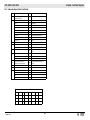
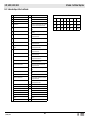
13.3 List of Engine Diagnostic Trouble Codes (DTCs) ............................. 130
14 Factory-Installed Options 144
14.1 Battery Charger ................................................................................ 144
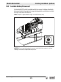
14.2 Lockable Battery Disconnect ............................................................ 145
14.3 Camlocks .......................................................................................... 146
14.4 Containment System ........................................................................ 147
14.5 Extended Run Tank (ERT) ............................................................... 147
14.6 Engine Block Heater ......................................................................... 148

Table of Contents
G70 / G100 / G130 / G150
wc_bo5100027027_02_FM10TOC.fm
10
14.7 Cold-Weather Thermostat .................................................................149
14.8 Low Coolant Shutdown .....................................................................150
14.9 Temperature-Activated Shutters .......................................................151
14.10 Positive Air Shutoff Valve ..................................................................152
14.11 Connecting an External Fuel Supply .................................................153
14.12 Lube Level Maintainer .......................................................................154
15 Machines with Aftertreatment Exhaust System 155
15.1 How the Aftertreatment Exhaust System Works ...............................155
15.2 Filling the DEF Tank ..........................................................................156
15.3 Shelf Life of Diesel Exhaust Fluid (DEF) ...........................................158
15.4 Monitoring and Control of the DEF Level ..........................................159
15.5 Monitoring DEF Quality .....................................................................160
15.6 Conditioning the Aftertreatment Exhaust System (if equipped) .........161
16 General Maintenance 162
16.1 Periodic Maintenance Schedule ........................................................162
16.2 Maintaining the Emission Control System .........................................163
16.3 Preparing for Maintenance ................................................................163
16.4 Cleaning the Machine ........................................................................163
16.5 Inspecting the Machine .....................................................................164
16.6 Maintaining the Trailer .......................................................................165
16.7 Checking and Draining the Containment System (if equipped) .........166
16.8 Checking the Exhaust System ..........................................................167
16.9 Maintaining the Battery ......................................................................168
16.10 Cleaning the Diesel Particulate Filter (DPF) (if equipped) .................169
16.11 Filling the Radiator ............................................................................170
16.12 Replacing the Aftertreatment DEF Dosing Unit Filter (if equipped) ...172
16.13 Storage ..............................................................................................174
16.14 Machine Disposal and Decommissioning ..........................................175
17 Engine Maintenance: T4F Cummins
QSB5-G10 / QSB5-G11 / QSB5-G12 176
18 Troubleshooting 180

Table of Contents
G70 / G100 / G130 / G150
wc_bo5100027027_02_FM10T
11
19 Technical Data 181
19.1 Engine: G70 / G100 .......................................................................... 181
19.2 Engine: G130 / G150 ........................................................................ 182
19.3 Machine ............................................................................................ 183
19.4 Trailer and Skid ................................................................................ 184
19.5 Dimensions ....................................................................................... 185
Tire Safety Information 187
20 User’s Information for Transport Canada Fuel Tank 199
21 Emission Control Systems Information and Warranty—Diesel 202
21.1 Emission Control System Background Information .......................... 202
21.2 Limited Defect Warranty for Exhaust Emission Control System ....... 203
21.3 Limited Defect Warranty for Wacker Neuson Emission Control
Systems ............................................................................................ 203
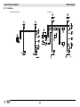
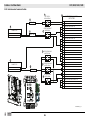
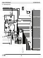
22 General Machine Schematics 207
22.1 Fuses ................................................................................................ 207
22.2 Trailer Wiring .................................................................................... 208
22.3 Trailer Wiring Components ............................................................... 209
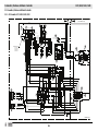
23 Schematics, Machines with Basler Controller 210
23.1 AC Schematic: G70 / G100 / G130 / G150 ...................................... 210
23.2 AC Schematic Components: G70 / G100 / G130 / G150 ................. 211
23.3 DC Schematic: G70 / G100 / G130 / G150 ...................................... 212
23.4 DC Schematic Components: G70 / G100 / G130 / G150 ................. 213
23.5 Electrical Schematic Section A ......................................................... 214
23.6 Electrical Schematic Components .................................................... 215
23.7 Electrical Schematic Section B ......................................................... 216
23.8 Electrical Schematic Components .................................................... 217
23.9 Electrical Schematic Section C ........................................................ 218
23.10 Electrical Schematic Components .................................................... 219
23.11 Cummins Engine Relays and Fuses ................................................ 220
23.12 Cummins Engine Relays and Fuses ................................................ 221

Table of Contents
G70 / G100 / G130 / G150
wc_bo5100027027_02_FM10TOC.fm
12
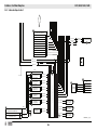
24 Schematics, Machines with Deep Sea Controller 222
24.1 AC Schematic: G70 / G100 / G130 / G150 .......................................222
24.2 Electrical Schematic Components: G70 / G100 / G130 / G150 ........223
24.3 DC Schematic: G70 / G100 / G130 / G150 .......................................224
24.4 DC Schematic Components: G70 / G100 / G130 / G150 ..................225
24.5 Electrical Schematic Section A ..........................................................226
24.6 Electrical Schematic Components .....................................................227
24.7 Electrical Schematic Section B ..........................................................228
24.8 Electrical Schematic Components .....................................................229
24.9 Electrical Schematic Section C .........................................................230
24.10 Electrical Schematic Components .....................................................231
24.11 Cummins Engine Relays and Fuses .................................................232
24.12 Cummins Engine Relays and Fuses .................................................233

wc_tx003567gb_FM10.fm
13
Mobile Generator Safety Information
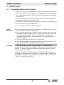
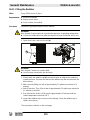
1 Safety Information
1.1 Signal Words Used in this Manual
This manual contains DANGER, WARNING, CAUTION, NOTICE, and NOTE
signal words which must be followed to reduce the possibility of personal injury,
damage to the equipment, or improper service.
NOTICE: Used without the safety alert symbol, NOTICE indicates a situation
which, if not avoided, could result in property damage.
Note: A Note contains additional information important to a procedure.
This is the safety alert symbol. It is used to alert you to potential personal hazards.
► Obey all safety messages that follow this symbol.
DANGER
DANGER indicates a hazardous situation which, if not avoided, will result in death
or serious injury.
► To avoid death or serious injury from this type of hazard, obey all safety
messages that follow this signal word.
WARNING
WARNING indicates a hazardous situation which, if not avoided, could result in
death or serious injury.
► To avoid possible death or serious injury from this type of hazard, obey all safety
messages that follow this signal word.
CAUTION
CAUTION indicates a hazardous situation which, if not avoided, could result in
minor or moderate injury.
► To avoid possible minor or moderate injury from this type of hazard, obey all
safety messages that follow this signal word.

wc_tx003567gb_FM10.fm
14
Safety Information Mobile Generator
1.2 Machine Description and Intended Use
Machine
description
This machine is a mobile electric power source. The Wacker Neuson Mobile
Generator consists of a trailer-mounted cabinet containing an electric alternator, a
fuel tank, and a diesel engine. A control panel, receptacles, and connection lugs
are provided on the side of the cabinet. As the engine runs, the generator converts
mechanical energy into electric power. The operator connects loads to the electric
power receptacles and connection lugs.
Intended use
This machine is intended for the purpose of supplying electrical power to
connected loads. Refer to the product specifications for the output voltage and
frequency of this generator, and for the maximum output power limit of this
generator.
This machine has been designed and built strictly for the intended use described
above. Using the machine for any other purpose could permanently damage the
machine or seriously injure the operator or other persons in the area. Machine
damage caused by misuse is not covered under warranty.
The following are some examples of misuse:
■ Connecting a load that has voltage and frequency requirements that are
incompatible with the generator output
■ Overloading the generator with a load that draws excessive power during either
continuous running or start-up
■ Operating the generator in a manner that is inconsistent with all federal, state
and local codes and regulations
■ Using the machine as a ladder, support, or work surface
■ Using the machine to carry or transport passengers or equipment
■ Using the machine to tow other machines
■ Operating the machine outside of factory specifications
■ Operating the machine in a manner inconsistent with all warnings found on the
machine and in the Operator’s Manual
This machine has been designed and built in accordance with the latest global
safety standards. It has been carefully engineered to eliminate hazards as far as
practicable and to increase operator safety through protective guards and labeling.
However, some risks may remain even after protective measures have been taken.
They are called residual risks. On this machine, they may include exposure to:
■ Heat, noise, exhaust, and carbon monoxide from the engine
■ Fire hazards from improper refueling techniques
■ Fuel and its fumes
■ Electric shock and arc flash
■ Personal injury from improper lifting the trailer tongue
■ Typical hazards related to towing a trailer on roads and highways
To protect yourself and others, make sure you thoroughly read and understand the
safety information presented in this manual before operating the machine.

wc_tx003567gb_FM10.fm
15
Mobile Generator Safety Information
1.3 Safety Guidelines for Operating the Machine
Operator
training
Before operating the machine:
■ Read and understand the operating instructions contained in all manuals
delivered with the machine.
■ Familiarize yourself with the location and proper use of all controls and safety
devices.
■ Contact Wacker Neuson for additional training if necessary.
When operating this machine:
■ Do not allow improperly trained people to operate the machine. People
operating the machine must be familiar with the potential risks and hazards
associated with it.
Operator
qualifications
Only trained personnel are permitted to start, operate, and shut down the machine.
They also must meet the following qualifications:
■ Have received instruction on how to properly use the machine
■ Are familiar with required safety devices
The machine must not be accessed or operated by:
■ Children
■ People impaired by alcohol, drugs or prescription drugs
Application
area
Be aware of the application area.
■ Keep unauthorized personnel, children, and pets away from the machine.
■ Remain aware of changing positions and the movement of other equipment and
personnel in the application area/job site.
■ Identify whether special hazards exist in the application area, such as toxic
gases or unstable ground conditions, and take appropriate action to eliminate
the special hazards before using the machine.
Be aware of the application area.
■ Do not operate the machine in areas that contain flammable objects, fuels, or
products that produce flammable vapors.
Safety
devices,
controls, and
attachments
Only operate the machine when:
■ All safety devices and guards are in place and in working order.
■ All controls operate correctly.
■ The machine is set up correctly according to the instructions in the Operator’s
Manual.
■ The machine is clean.
■ The machine’s labels are legible.
To ensure safe operation of the machine:
■ Do not operate the machine if any safety devices or guards are missing or
inoperative.
■ Do not modify or defeat the safety devices.
■ Only use accessories or attachments that are approved by Wacker Neuson.

wc_tx003567gb_FM10.fm
16
Safety Information Mobile Generator
Safe
operating
practices
When operating this machine:
■ Remain aware of the machine’s moving parts. Keep hands, feet, and loose
clothing away from the machine’s moving parts.
When operating this machine:
■ Do not operate a machine in need of repair.
■ Do not consume the operating fluids used in this machine. Depending on your
machine model, these operating fluids may include water, wetting agents, fuel
(gasoline, diesel, kerosene, propane, or natural gas), oil, coolant, hydraulic fluid,
heat transfer fluid (propylene glycol with additives), battery acid, or grease.
Personal
Protective
Equipment
(PPE)
Wear the following Personal Protective Equipment (PPE) while operating this
machine:
■ Close-fitting work clothes that do not hinder movement
■ Safety glasses with side shields
■ Hearing protection
■ Safety-toed footwear
After use
■ Stop the engine when the machine is not being operated.
■ Close the fuel valve on engines equipped with one when the machine is not
being operated.
■ Ensure that the machine will not tip over, roll, slide, or fall when not being
operated.
■ Store the machine properly when it is not being used. The machine should be
stored in a clean location out of the reach of children.

wc_tx003567gb_FM10.fm
17
Mobile Generator Safety Information
1.4 Service Safety
Service
training
Before servicing or maintaining the machine:
■ Read and understand the instructions contained in all manuals delivered with
the machine.
■ Familiarize yourself with the location and proper use of all controls and
protective devices.
■ Only trained personnel shall troubleshoot or repair problems occurring with the
machine.
■ Contact Wacker Neuson for additional training if necessary.
When servicing or maintaining this machine:
■ Do not allow untrained or improperly trained people to service or maintain the
machine. Personnel servicing or maintaining the machine must be familiar with
the associated potential risks and hazards.
■ Maintenance items that can be performed by the operator are listed in this
manual. Other repairs should be performed by a qualified technician. Repairs
can be hazardous if not performed correctly. Contact your Wacker Neuson
dealer service department for additional information or for repairs to your
machine.
Precautions
When servicing or maintaining the machine:
■ Read and understand the service procedures before performing any service to
the machine.
■ All adjustments and repairs must be completed before operating the machine.
Do not operate the machine with a known problem or deficiency.
■ All repairs and adjustments shall be completed by a qualified technician.
■ Turn off the machine before performing maintenance or making repairs.
■ Remain aware of the machine’s moving parts. Keep hands, feet, and loose
clothing away from the machine’s moving parts.
■ Re-install the safety devices and guards after repair and maintenance
procedures are complete.
Machine
modifications
When servicing or maintaining the machine:
■ Use only accessories/attachments that are approved by Wacker Neuson.
■ Do not defeat safety devices.
■ Do not modify the machine without the express written approval of Wacker
Neuson.
Replacing
parts and
labels
■ Replace worn or damaged components.
■ Replace all missing and hard-to-read labels.
■ When replacing electrical components, use components that are identical in
rating and performance to the original components.
■ When replacement parts are required for this machine, use only Wacker
Neuson replacement parts or those parts equivalent to the original in all types of
specifications, such as physical dimensions, type, strength, and material.

wc_tx003567gb_FM10.fm
18
Safety Information Mobile Generator
Cleaning
When cleaning and servicing the machine:
■ Keep machine clean and free of debris such as leaves, paper, cartons, etc.
■ Keep labels legible.
■ Clean with soapy water only.
When cleaning the machine:
■ Do not clean the machine while it is running.
■ Never use gasoline or other types of fuels or flammable solvents to clean the
machine. Fumes from fuels and solvents can become explosive.
Personal
Protective
Equipment
(PPE)
Wear the following Personal Protective Equipment (PPE) while servicing or
maintaining this machine:
■ Close-fitting work clothes that do not hinder movement
■ Safety glasses with side shields
■ Hearing protection
■ Safety-toed footwear
In addition, before servicing or maintaining the machine:
■ Tie back long hair.
■ Remove all jewelry (including rings).
Electrical
service safety
■ Make sure clothing and shoes are dry, stand on a dry wooden platform or rubber
insulating mat, and use tools with insulated handles when servicing the
machine.
■ Do not allow water to accumulate around the base of the machine. If water is
present, move the machine and allow the machine to dry before servicing.
■ Do not pressure wash the control panel, generator end, or any other electrical
components when cleaning the machine.
Cooling
system safety
■ Do not attempt to open the radiator cap while the unit is running or before the
engine has cooled down. Severe burns may result!
■ Engine coolant is toxic to humans and animals. Clean up spills and dispose of
waste engine coolant in accordance with local environmental regulations.

wc_tx003567gb_FM10.fm
19
Mobile Generator Safety Information
1.5 Operator Safety while Using Internal Combustion Engines
Operating
safety
When running the engine:
■ Keep the area around the exhaust pipe free of flammable materials.
■ Check the fuel lines and the fuel tank for leaks and cracks before starting the
engine. Do not run the machine if fuel leaks are present or the fuel lines are
loose.
When running the engine:
■ Do not smoke while operating the machine.
■ Do not run the engine near sparks or open flames.
■ Do not touch the engine or muffler while the engine is running or immediately
after it has been turned off.
■ Do not operate a machine when its fuel cap is loose or missing.
■ Do not start the engine if fuel has spilled or a fuel odor is present. Move the
machine away from the spill and wipe the machine dry before starting.
Refueling
safety
When refueling the engine:
■ Clean up any spilled fuel immediately.
■ Refill the fuel tank in a well-ventilated area.
■ Re-install the fuel tank cap after refueling.
■ Use suitable tools for refueling (for example, a fuel hose or funnel).
When refueling the engine:
■ Do not smoke.
■ Do not refuel a hot or running engine.
■ Do not refuel the engine near sparks or open flames.
WARNING
Internal combustion engines present special hazards during operation and fueling.
Failure to follow the warnings and safety standards could result in severe injury or
death.
► Read and follow the warning instructions in the engine owner’s manual and the
safety guidelines below.
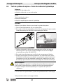
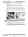
DANGER
Exhaust gas from the engine contains carbon monoxide, a deadly poison.
Exposure to carbon monoxide can kill you in minutes.
► NEVER operate the machine inside an enclosed area, such as a tunnel, unless
adequate ventilation is provided through items such as exhaust fans or hoses.

wc_tx003567gb_FM10.fm
20
Safety Information Mobile Generator
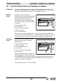
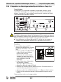
1.6 Safety Guidelines for Mobile Generators
Installing as
backup power
Special hazards exist when installing this machine as a backup power supply.
Improper connection of generator to a building’s electrical system can allow
electrical current from the generator to backfeed into utility lines. This may result in
electrocution of utility workers, fire, or explosion.
If connected to a building’s electrical system, the generator must meet the power,
voltage, and frequency requirements of the equipment in the building. Differences
in power, voltage, and frequency requirements may exist and improper connection
may lead to equipment damage, fire, and personal injury or death.
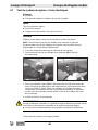
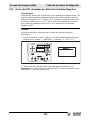
DANGER
Carbon monoxide. Using a generator indoors CAN KILL YOU IN MINUTES.
Generator exhaust contains carbon monoxide (CO). This is a poison you cannot
see or smell. If you can smell the generator exhaust, you are breathing CO. Even if
you cannot smell the exhaust, you could be breathing CO.
► NEVER use a generator inside homes, garages, crawlspaces, or other partly
enclosed areas. Deadly levels of carbon monoxide can build up in these areas.
Using a fan or opening windows and doors does NOT supply enough fresh air.
► ONLY use a generator outside and far away from windows, doors, and vents.
These openings can pull in generator exhaust.
► Even when you use a generator correctly, CO may leak into the home. ALWAYS
use a battery-powered or battery-backup CO alarm in the home.
► If you start to feel sick, dizzy, or weak after the generator has been running,
move to fresh air RIGHT AWAY. See a doctor. You could have carbon monoxide
poisoning.
WARNING
Electrocution hazard. Machines that generate electric power present special
hazards while the engine is running. These include the risk of electrocution or
severe electrical shock.
► Read and follow the instructions in this Operator’s Manual.
WARNING
Backfeed from the generator into the public power distribution system can cause
serious injury or death to utility workers!
► Connections to a building’s electrical system must be made by a qualified
electrician and comply with all applicable laws and electrical codes.
Page is loading ...
Page is loading ...
Page is loading ...
Page is loading ...
Page is loading ...
Page is loading ...
Page is loading ...
Page is loading ...
Page is loading ...
Page is loading ...
Page is loading ...
Page is loading ...
Page is loading ...
Page is loading ...
Page is loading ...
Page is loading ...
Page is loading ...
Page is loading ...
Page is loading ...
Page is loading ...
Page is loading ...
Page is loading ...
Page is loading ...
Page is loading ...
Page is loading ...
Page is loading ...
Page is loading ...
Page is loading ...
Page is loading ...
Page is loading ...
Page is loading ...
Page is loading ...
Page is loading ...
Page is loading ...
Page is loading ...
Page is loading ...
Page is loading ...
Page is loading ...
Page is loading ...
Page is loading ...
Page is loading ...
Page is loading ...
Page is loading ...
Page is loading ...
Page is loading ...
Page is loading ...
Page is loading ...
Page is loading ...
Page is loading ...
Page is loading ...
Page is loading ...
Page is loading ...
Page is loading ...
Page is loading ...
Page is loading ...
Page is loading ...
Page is loading ...
Page is loading ...
Page is loading ...
Page is loading ...
Page is loading ...
Page is loading ...
Page is loading ...
Page is loading ...
Page is loading ...
Page is loading ...
Page is loading ...
Page is loading ...
Page is loading ...
Page is loading ...
Page is loading ...
Page is loading ...
Page is loading ...
Page is loading ...
Page is loading ...
Page is loading ...
Page is loading ...
Page is loading ...
Page is loading ...
Page is loading ...
Page is loading ...
Page is loading ...
Page is loading ...
Page is loading ...
Page is loading ...
Page is loading ...
Page is loading ...
Page is loading ...
Page is loading ...
Page is loading ...
Page is loading ...
Page is loading ...
Page is loading ...
Page is loading ...
Page is loading ...
Page is loading ...
Page is loading ...
Page is loading ...
Page is loading ...
Page is loading ...
Page is loading ...
Page is loading ...
Page is loading ...
Page is loading ...
Page is loading ...
Page is loading ...
Page is loading ...
Page is loading ...
Page is loading ...
Page is loading ...
Page is loading ...
Page is loading ...
Page is loading ...
Page is loading ...
Page is loading ...
Page is loading ...
Page is loading ...
Page is loading ...
Page is loading ...
Page is loading ...
Page is loading ...
Page is loading ...
Page is loading ...
Page is loading ...
Page is loading ...
Page is loading ...
Page is loading ...
Page is loading ...
Page is loading ...
Page is loading ...
Page is loading ...
Page is loading ...
Page is loading ...
Page is loading ...
Page is loading ...
Page is loading ...
Page is loading ...
Page is loading ...
Page is loading ...
Page is loading ...
Page is loading ...
Page is loading ...
Page is loading ...
Page is loading ...
Page is loading ...
Page is loading ...
Page is loading ...
Page is loading ...
Page is loading ...
Page is loading ...
Page is loading ...
Page is loading ...
Page is loading ...
Page is loading ...
Page is loading ...
Page is loading ...
Page is loading ...
Page is loading ...
Page is loading ...
Page is loading ...
Page is loading ...
Page is loading ...
Page is loading ...
Page is loading ...
Page is loading ...
Page is loading ...
Page is loading ...
Page is loading ...
Page is loading ...
Page is loading ...
Page is loading ...
Page is loading ...
Page is loading ...
Page is loading ...
Page is loading ...
Page is loading ...
Page is loading ...
Page is loading ...
Page is loading ...
Page is loading ...
Page is loading ...
Page is loading ...
Page is loading ...
Page is loading ...
Page is loading ...
Page is loading ...
Page is loading ...
Page is loading ...
Page is loading ...
Page is loading ...
Page is loading ...
Page is loading ...
Page is loading ...
Page is loading ...
Page is loading ...
Page is loading ...
Page is loading ...
Page is loading ...
Page is loading ...
Page is loading ...
Page is loading ...
Page is loading ...
Page is loading ...
Page is loading ...
Page is loading ...
Page is loading ...
Page is loading ...
Page is loading ...
Page is loading ...
Page is loading ...
Page is loading ...
Page is loading ...
Page is loading ...
Page is loading ...
Page is loading ...
Page is loading ...
Page is loading ...
Page is loading ...
Page is loading ...
Page is loading ...
Page is loading ...
Page is loading ...
Page is loading ...
Page is loading ...
Page is loading ...
Page is loading ...
Page is loading ...
Page is loading ...
Page is loading ...
Page is loading ...
Page is loading ...
Page is loading ...
Page is loading ...
Page is loading ...
Page is loading ...
Page is loading ...
Page is loading ...
Page is loading ...
Page is loading ...
Page is loading ...
Page is loading ...
Page is loading ...
Page is loading ...
Page is loading ...
Page is loading ...
Page is loading ...
Page is loading ...
Page is loading ...
Page is loading ...
Page is loading ...
Page is loading ...
Page is loading ...
Page is loading ...
Page is loading ...
Page is loading ...
Page is loading ...
Page is loading ...
Page is loading ...
Page is loading ...
Page is loading ...
Page is loading ...
Page is loading ...
Page is loading ...
Page is loading ...
Page is loading ...
Page is loading ...
Page is loading ...
Page is loading ...
Page is loading ...
Page is loading ...
Page is loading ...
Page is loading ...
Page is loading ...
Page is loading ...
Page is loading ...
Page is loading ...
Page is loading ...
Page is loading ...
Page is loading ...
Page is loading ...
Page is loading ...
Page is loading ...
Page is loading ...
Page is loading ...
Page is loading ...
Page is loading ...
Page is loading ...
Page is loading ...
Page is loading ...
Page is loading ...
Page is loading ...
Page is loading ...
Page is loading ...
Page is loading ...
Page is loading ...
Page is loading ...
Page is loading ...
Page is loading ...
Page is loading ...
Page is loading ...
Page is loading ...
Page is loading ...
Page is loading ...
Page is loading ...
Page is loading ...
Page is loading ...
Page is loading ...
Page is loading ...
Page is loading ...
Page is loading ...
Page is loading ...
Page is loading ...
Page is loading ...
Page is loading ...
Page is loading ...
Page is loading ...
Page is loading ...
Page is loading ...
Page is loading ...
Page is loading ...
Page is loading ...
Page is loading ...
Page is loading ...
Page is loading ...
Page is loading ...
Page is loading ...
Page is loading ...
Page is loading ...
Page is loading ...
Page is loading ...
Page is loading ...
Page is loading ...
Page is loading ...
Page is loading ...
Page is loading ...
Page is loading ...
Page is loading ...
Page is loading ...
Page is loading ...
Page is loading ...
Page is loading ...
Page is loading ...
Page is loading ...
Page is loading ...
Page is loading ...
Page is loading ...
Page is loading ...
Page is loading ...
Page is loading ...
Page is loading ...
Page is loading ...
Page is loading ...
Page is loading ...
Page is loading ...
Page is loading ...
Page is loading ...
Page is loading ...
Page is loading ...
Page is loading ...
Page is loading ...
Page is loading ...
Page is loading ...
Page is loading ...
Page is loading ...
Page is loading ...
Page is loading ...
Page is loading ...
Page is loading ...
Page is loading ...
Page is loading ...
Page is loading ...
Page is loading ...
Page is loading ...
Page is loading ...
Page is loading ...
Page is loading ...
Page is loading ...
Page is loading ...
Page is loading ...
Page is loading ...
Page is loading ...
Page is loading ...
Page is loading ...
Page is loading ...
Page is loading ...
Page is loading ...
Page is loading ...
Page is loading ...
Page is loading ...
Page is loading ...
Page is loading ...
Page is loading ...
Page is loading ...
Page is loading ...
Page is loading ...
Page is loading ...
Page is loading ...
Page is loading ...
Page is loading ...
Page is loading ...
Page is loading ...
Page is loading ...
Page is loading ...
Page is loading ...
Page is loading ...
Page is loading ...
Page is loading ...
Page is loading ...
Page is loading ...
Page is loading ...
Page is loading ...
Page is loading ...
Page is loading ...
Page is loading ...
Page is loading ...
Page is loading ...
Page is loading ...
Page is loading ...
Page is loading ...
Page is loading ...
Page is loading ...
Page is loading ...
Page is loading ...
Page is loading ...
Page is loading ...
Page is loading ...
Page is loading ...
Page is loading ...
Page is loading ...
Page is loading ...
Page is loading ...
Page is loading ...
Page is loading ...
Page is loading ...
Page is loading ...
Page is loading ...
Page is loading ...
Page is loading ...
Page is loading ...
Page is loading ...
Page is loading ...
Page is loading ...
Page is loading ...
Page is loading ...
Page is loading ...
Page is loading ...
Page is loading ...
Page is loading ...
Page is loading ...
Page is loading ...
Page is loading ...
Page is loading ...
Page is loading ...
Page is loading ...
Page is loading ...
Page is loading ...
Page is loading ...
Page is loading ...
Page is loading ...
Page is loading ...
Page is loading ...
Page is loading ...
Page is loading ...
Page is loading ...
Page is loading ...
Page is loading ...
Page is loading ...
Page is loading ...
Page is loading ...
Page is loading ...
Page is loading ...
Page is loading ...
Page is loading ...
Page is loading ...
Page is loading ...
Page is loading ...
-
 1
1
-
 2
2
-
 3
3
-
 4
4
-
 5
5
-
 6
6
-
 7
7
-
 8
8
-
 9
9
-
 10
10
-
 11
11
-
 12
12
-
 13
13
-
 14
14
-
 15
15
-
 16
16
-
 17
17
-
 18
18
-
 19
19
-
 20
20
-
 21
21
-
 22
22
-
 23
23
-
 24
24
-
 25
25
-
 26
26
-
 27
27
-
 28
28
-
 29
29
-
 30
30
-
 31
31
-
 32
32
-
 33
33
-
 34
34
-
 35
35
-
 36
36
-
 37
37
-
 38
38
-
 39
39
-
 40
40
-
 41
41
-
 42
42
-
 43
43
-
 44
44
-
 45
45
-
 46
46
-
 47
47
-
 48
48
-
 49
49
-
 50
50
-
 51
51
-
 52
52
-
 53
53
-
 54
54
-
 55
55
-
 56
56
-
 57
57
-
 58
58
-
 59
59
-
 60
60
-
 61
61
-
 62
62
-
 63
63
-
 64
64
-
 65
65
-
 66
66
-
 67
67
-
 68
68
-
 69
69
-
 70
70
-
 71
71
-
 72
72
-
 73
73
-
 74
74
-
 75
75
-
 76
76
-
 77
77
-
 78
78
-
 79
79
-
 80
80
-
 81
81
-
 82
82
-
 83
83
-
 84
84
-
 85
85
-
 86
86
-
 87
87
-
 88
88
-
 89
89
-
 90
90
-
 91
91
-
 92
92
-
 93
93
-
 94
94
-
 95
95
-
 96
96
-
 97
97
-
 98
98
-
 99
99
-
 100
100
-
 101
101
-
 102
102
-
 103
103
-
 104
104
-
 105
105
-
 106
106
-
 107
107
-
 108
108
-
 109
109
-
 110
110
-
 111
111
-
 112
112
-
 113
113
-
 114
114
-
 115
115
-
 116
116
-
 117
117
-
 118
118
-
 119
119
-
 120
120
-
 121
121
-
 122
122
-
 123
123
-
 124
124
-
 125
125
-
 126
126
-
 127
127
-
 128
128
-
 129
129
-
 130
130
-
 131
131
-
 132
132
-
 133
133
-
 134
134
-
 135
135
-
 136
136
-
 137
137
-
 138
138
-
 139
139
-
 140
140
-
 141
141
-
 142
142
-
 143
143
-
 144
144
-
 145
145
-
 146
146
-
 147
147
-
 148
148
-
 149
149
-
 150
150
-
 151
151
-
 152
152
-
 153
153
-
 154
154
-
 155
155
-
 156
156
-
 157
157
-
 158
158
-
 159
159
-
 160
160
-
 161
161
-
 162
162
-
 163
163
-
 164
164
-
 165
165
-
 166
166
-
 167
167
-
 168
168
-
 169
169
-
 170
170
-
 171
171
-
 172
172
-
 173
173
-
 174
174
-
 175
175
-
 176
176
-
 177
177
-
 178
178
-
 179
179
-
 180
180
-
 181
181
-
 182
182
-
 183
183
-
 184
184
-
 185
185
-
 186
186
-
 187
187
-
 188
188
-
 189
189
-
 190
190
-
 191
191
-
 192
192
-
 193
193
-
 194
194
-
 195
195
-
 196
196
-
 197
197
-
 198
198
-
 199
199
-
 200
200
-
 201
201
-
 202
202
-
 203
203
-
 204
204
-
 205
205
-
 206
206
-
 207
207
-
 208
208
-
 209
209
-
 210
210
-
 211
211
-
 212
212
-
 213
213
-
 214
214
-
 215
215
-
 216
216
-
 217
217
-
 218
218
-
 219
219
-
 220
220
-
 221
221
-
 222
222
-
 223
223
-
 224
224
-
 225
225
-
 226
226
-
 227
227
-
 228
228
-
 229
229
-
 230
230
-
 231
231
-
 232
232
-
 233
233
-
 234
234
-
 235
235
-
 236
236
-
 237
237
-
 238
238
-
 239
239
-
 240
240
-
 241
241
-
 242
242
-
 243
243
-
 244
244
-
 245
245
-
 246
246
-
 247
247
-
 248
248
-
 249
249
-
 250
250
-
 251
251
-
 252
252
-
 253
253
-
 254
254
-
 255
255
-
 256
256
-
 257
257
-
 258
258
-
 259
259
-
 260
260
-
 261
261
-
 262
262
-
 263
263
-
 264
264
-
 265
265
-
 266
266
-
 267
267
-
 268
268
-
 269
269
-
 270
270
-
 271
271
-
 272
272
-
 273
273
-
 274
274
-
 275
275
-
 276
276
-
 277
277
-
 278
278
-
 279
279
-
 280
280
-
 281
281
-
 282
282
-
 283
283
-
 284
284
-
 285
285
-
 286
286
-
 287
287
-
 288
288
-
 289
289
-
 290
290
-
 291
291
-
 292
292
-
 293
293
-
 294
294
-
 295
295
-
 296
296
-
 297
297
-
 298
298
-
 299
299
-
 300
300
-
 301
301
-
 302
302
-
 303
303
-
 304
304
-
 305
305
-
 306
306
-
 307
307
-
 308
308
-
 309
309
-
 310
310
-
 311
311
-
 312
312
-
 313
313
-
 314
314
-
 315
315
-
 316
316
-
 317
317
-
 318
318
-
 319
319
-
 320
320
-
 321
321
-
 322
322
-
 323
323
-
 324
324
-
 325
325
-
 326
326
-
 327
327
-
 328
328
-
 329
329
-
 330
330
-
 331
331
-
 332
332
-
 333
333
-
 334
334
-
 335
335
-
 336
336
-
 337
337
-
 338
338
-
 339
339
-
 340
340
-
 341
341
-
 342
342
-
 343
343
-
 344
344
-
 345
345
-
 346
346
-
 347
347
-
 348
348
-
 349
349
-
 350
350
-
 351
351
-
 352
352
-
 353
353
-
 354
354
-
 355
355
-
 356
356
-
 357
357
-
 358
358
-
 359
359
-
 360
360
-
 361
361
-
 362
362
-
 363
363
-
 364
364
-
 365
365
-
 366
366
-
 367
367
-
 368
368
-
 369
369
-
 370
370
-
 371
371
-
 372
372
-
 373
373
-
 374
374
-
 375
375
-
 376
376
-
 377
377
-
 378
378
-
 379
379
-
 380
380
-
 381
381
-
 382
382
-
 383
383
-
 384
384
-
 385
385
-
 386
386
-
 387
387
-
 388
388
-
 389
389
-
 390
390
-
 391
391
-
 392
392
-
 393
393
-
 394
394
-
 395
395
-
 396
396
-
 397
397
-
 398
398
-
 399
399
-
 400
400
-
 401
401
-
 402
402
-
 403
403
-
 404
404
-
 405
405
-
 406
406
-
 407
407
-
 408
408
-
 409
409
-
 410
410
-
 411
411
-
 412
412
-
 413
413
-
 414
414
-
 415
415
-
 416
416
-
 417
417
-
 418
418
-
 419
419
-
 420
420
-
 421
421
-
 422
422
-
 423
423
-
 424
424
-
 425
425
-
 426
426
-
 427
427
-
 428
428
-
 429
429
-
 430
430
-
 431
431
-
 432
432
-
 433
433
-
 434
434
-
 435
435
-
 436
436
-
 437
437
-
 438
438
-
 439
439
-
 440
440
-
 441
441
-
 442
442
-
 443
443
-
 444
444
-
 445
445
-
 446
446
-
 447
447
-
 448
448
-
 449
449
-
 450
450
-
 451
451
-
 452
452
-
 453
453
-
 454
454
-
 455
455
-
 456
456
-
 457
457
-
 458
458
-
 459
459
-
 460
460
-
 461
461
-
 462
462
-
 463
463
-
 464
464
-
 465
465
-
 466
466
-
 467
467
-
 468
468
-
 469
469
-
 470
470
-
 471
471
-
 472
472
-
 473
473
-
 474
474
-
 475
475
-
 476
476
-
 477
477
-
 478
478
-
 479
479
-
 480
480
-
 481
481
-
 482
482
-
 483
483
-
 484
484
-
 485
485
-
 486
486
-
 487
487
-
 488
488
-
 489
489
-
 490
490
-
 491
491
-
 492
492
-
 493
493
-
 494
494
-
 495
495
-
 496
496


Wacker Neuson G130 User manual
- Category
- Power generators
- Type
- User manual
Ask a question and I''ll find the answer in the document
Finding information in a document is now easier with AI
in other languages
- français: Wacker Neuson G130 Manuel utilisateur
Related papers
Other documents
-
Smartgen HGM8110ZDC Owner's manual
-
Broan B6BV Product information
-
-
-
MQ Power DEFTANK Operating instructions
-
-
Powerfist 8138844 Owner's manual
-
 ALERTEGPS G100 Owner's manual
-
 ALERTEGPS GPS PREVENT G100 Owner's manual
-

