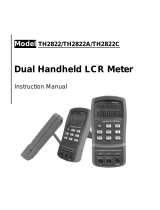
Page is loading ...

LCR-Messgerät LCR-300
쮕
BEDIENUNGSANLEITUNG Seite 2 - 31
LCR Measuring Device LCR-300
OPERATING INSTRUCTIONS Page 32 - 53
Instrument de mesure LCR LCR-300
MODE D’EMPLOI Page 54 - 89
LCR-Meetapparaat LCR-300
GEBRUIKSAANWIJZING Pagina 90 - 121
Best.-Nr. / Item no. /
N° de commande / Bestelnr.:
10 36 77
Version 10/12
®

32
1. INTRODUCTION
Dear customer,
Thank you for making the excellent decision of purchasing this Voltcraft® product.
You have acquired a quality product from a brand family which has distinguished itself in the fi elds
of measuring, charging and network technology thanks to its particular expertise and its continuous
innovation.
With Voltcraft®, you will be able to cope even with diffi cult tasks as an ambitious hobbyist or as a
professional user. Voltcraft® offers reliable technology and a great price-performance-ratio.
We are positive: Starting to work with Voltcraft will also be the beginning of a long, successful relation-
ship.
Enjoy your new Voltcraft® product!

33
2. TABLE OF CONTENTS
1. Introduction ......................................................................................................................................32
2. Table of Contents .............................................................................................................................33
3. Scope of Delivery ............................................................................................................................34
4. Intended Use ...................................................................................................................................34
5. Control Elements .............................................................................................................................35
5.1. Display Indications and Symbols ............................................................................................36
6. Safety Information ...........................................................................................................................37
7. Product Description .........................................................................................................................39
7.1. Functional Description ............................................................................................................39
7.2. Switching on the Meter ...........................................................................................................39
7.3. Select Measuring Function .....................................................................................................40
7.4. Select Measuring Frequency ..................................................................................................40
7.5. Hold Function ..........................................................................................................................41
7.6. REL Function ..........................................................................................................................41
7.7. Calibration ...............................................................................................................................42
7.8. Equivalent Switching Circuit ....................................................................................................43
7.9. Sorting Mode ...........................................................................................................................44
8. Measuring ........................................................................................................................................45
8.1. Selection of Measuring Inputs .................................................................................................45
8.2. Inductivity Measurement .........................................................................................................46
8.3. Capacity Measuring ................................................................................................................47
8.4. Resistance Measuring ............................................................................................................48
9. Optional Mains Unit Operation ........................................................................................................49
10. Cleaning and Maintenance ..............................................................................................................49
10.1. General Information ................................................................................................................49
10.2. Cleaning ..................................................................................................................................49
10.3. Inserting and Changing the Batteries ......................................................................................50
11. Disposal ...........................................................................................................................................51
11.1. Product ....................................................................................................................................51
11.2. Batteries and Rechargeable Batteries ....................................................................................51
12. Troubleshooting ...............................................................................................................................52
13. Technical Data .................................................................................................................................53

34
3. SCOPE OF DELIVERY
LCR measuring device
6 micro batteries (type AAA)
2 Kelvin measuring lines, red and black
2 calibration plugs (“OPEN” / “SHORT”)
Bag
Operating instructions
4. INTENDED USE
- Measuring and displaying the electrical values of coils (L), capacitators (C) and resistors (R) and their
combinations (parallel/serial)
- Measuring inductivities of up to 2000 H
- Capacity measurement up to 20 mF
- Measuring resistors (AC-R/DC-R) of up to 200 MOhm
- Displaying the quality factor “Q”
- Displaying the electrical loss factor “D”
- Displaying the phase angle “θ” (0.00° to ±180.0°)
The measurement functions and measuring ranges are selected using the pushbuttons. Automatic
measuring range selection is active in all measuring areas.
Components must only be connected to the measuring device when powered down and discharged.
No voltages must be applied to the measuring device.
The measuring device must not be operated when it is open, i.e. with an open battery compartment or
when the battery compartment cover is missing. Measurement under unfavourable ambient conditions
is not permitted.
Unfavourable ambient conditions are:
- dust and fl ammable gases, vapours or solvents,
- thunderstorms or similar conditions such as strong electrostatic fi elds, etc.
For safety reasons, only use measuring lines or accessories which are adjusted to the specifi cations of
the multimeter when measuring.
Any use other than that described above damages the product. Moreover, this is linked to dangers
such as short circuit, fi re, electric shock, etc. No part of the product must be modifi ed or converted!
Read the operating instructions carefully and keep them for later reference.
Always observe the safety information!

35
5. CONTROL ELEMENTS
See fold-out page
1 Display (LCD)
2 Operating button
3 FUNC. button: Switching button for measuring functions
4 CAL button: To perform device calibration for precise measured values
5 Rear battery compartment and folding setup bracket
6 SORTING button: For quick sorting measurements for tolerance determinations
7 Arrow up
8 HOLD button to “freeze” the displayed value
9 D/Q/ESR button: Switching display parameters in L/C measuring operation, arrow to the left
10 SETUP button: To set the reference and tolerance parameters in sorting mode
11 SER/PAL button: To toggle serial and parallel mode, arrow to the right
12 FREQ button: To switch the measuring frequency
13 REL% button: To display the relative deviation in % from a reference value; arrow down
14 Light button to activate and deactivate the display lighting
15 ENTER button: To confi rm the input in sorting mode
16 Lateral mains adapter socket
17 Connection and measuring sockets
18 Plug “OPEN” for insulation of the integrated measuring contacts in measuring line operation
19 Calibration plug “SHORT” for zero calibration
20 Four-conductor measuring terminals with shield (Kelvin measuring lines)

36
5.1. DISPLAY INDICATIONS AND SYMBOLS
A Bar chart shows utilisation of the measured range in %
B Function and operating displays
Ext-Power shows mains unit operation
Sorting shows sorting mode
CAL shows calibration mode
Tol shows the pre-set tolerance range for sorting
120 100 KHz shows the measuring frequency
Battery symbol shows the battery status in battery operation
C Main parameter for measuring operation
s = serial for serial circuits in AC operation (Ls, Cs, Rs)
p = parallel for parallel circuits in AC operation (Lp, Cp, Rp)
DCR = direct current resistance (DC)
D Symbol for active automatic deactivation
E Measuring functions
HOLD Data hold is active, the displayed measured value is stored
AUTO
Automatic measuring operation with pre-selection of the measuring parameter (L, C, R)
AUTO LCR
Smart automatic measuring operation without pre-selection of the measuring parameter
RANGE: Range display in sorting mode
REL Reference value display mode
F Main display with measuring units
G Sub-display with measuring units
H Subfunctions for the subdisplay
ESR Equivalent serial resistor
RP Equivalent parallel resistor
DQθ D = dissipation factor , Q = quality, θ = phase angle

37
6. SAFETY INFORMATION
Please read the operating instructions completely before taking the device into
operation. They contain important information for correct operation.
The guarantee/warranty will expire if damage is incurred resulting from non-compli-
ance with the operating instructions! We do not assume any liability for consequen-
tial damage!
We do not assume any liability for property damage and personal injury caused by
improper use or non-compliance with the safety instructions! In such cases the war-
ranty/guarantee expires.
This device left the manufacturer’s factory in safe and perfect condition.
To maintain this condition and to ensure safe operation, the user must observe the safety information
and warning notes in these operating instructions.
Observe the following symbols:
An exclamation mark in a triangle shows important notes in these operating instructions that
must be strictly observed.
The “arrow” symbol indicates that special advice and notes on operation are provided.
This device is CE-compliance and meets the applicable European directives
Earth potential
For safety and licensing reasons (CE), unauthorised conversion and/or modifi cation of the device is not
permitted.
Consult an expert when in doubt as to the operation, safety or the connection of the device.
Meters and accessories are not toys and have no place in the hands of children!
At industrial sites, the accident prevention regulations of the association of the industrial workers’ socie-
ties for electrical equipment and utilities must be followed.
In schools, training centres, computer and self-help workshops, handling of meters must be supervised
by trained personnel in a responsible manner.
Ensure before any measurement that all components are powered down and discharged.
The measuring prods have to be removed from the measured object every time the measuring range is
changed.
Be especially careful when dealing with voltages higher than 25 V alternating (AC) or 35 V direct volt-
age (DC)! Even at these voltages it is possible to receive a potentially fatal electric shock if you touch
electrical conductors.

38
Check the meter and its measuring lines for damage before each measurement. Never carry out any
measurements if the protecting insulation is defective (torn, ripped off etc.).
Make sure not to touch the connections/measuring points to be measured directly or indirectly during
measurement. Never reach beyond the noticeable grip area marks at the measuring prods during
measurements.
Avoid operation in direct proximity of strong magnetic or electromagnetic fi elds, transmitter aerials or
HF generators. This could affect the measurement.
If you have reason to believe that the device can no longer be operated safely, disconnect it imme-
diately and make sure it is not unintentionally operated. It can be assumed that safe operation is no
longer possible if:
- the device shows any visible damage,
- the device no longer works and
- the device was stored under unfavourable conditions for an extended period of time or
- after it was exposed to extraordinary stress caused by transport.
Do not switch the meter on immediately after it was taken from a cold to a warm environment. The
condensation that forms might destroy your device. Allow the device to reach room temperature before
switching it on.
Do not leave the packaging material lying around carelessly since such materials can become danger-
ous toys in the hands of children.
Also observe the safety information in each chapter of these instructions.

39
7. PRODUCT DESCRIPTION
The measured values are displayed in a digital display together with the units and icons on the multim-
eter (referred to as DMM in the following). The measured value display of the DMM comprises up to
19,999 counts (count = smallest display value).
If the DMM is not operated for approx. 5 minutes in battery operation, it switches off automatically. This
saves battery power and extends the period of operation. Automatic switching off is deactivated when
using the optional mains unit.
The meter can be used for do-it-yourself or for professional applications.
For better readability, the DMM can also be optimally mounted with the standing bracket on the rear.
7.1. FUNCTIONAL DESCRIPTION
The individual measuring functions are selected via functional button “FUNC”. Automatic area selection
is active in all measuring functions. The appropriate measurement range is set individually for each
application.
The DMM has two measuring inputs that are directly connected. Components with long connection
wires can be plugged in directly to the device and measured. Components with connections that are
too short can be contacted via the measuring lines that are connected to the sockets. The measur-
ing lines are performed in shielded 4-conductor technology to avoid measuring deviations by the line
resistors.
The display can be lighted in low light. Press the light button (14). The display lighting remains on for
about 60 seconds and switches off automatically again. To deactivate the lighting before this, push the
light button again.
7.2. SWITCHING ON THE MEASURING DEIVCE
Before working with the meter, you have to insert the enclosed batteries. Insertion
and changing of the batteries is described in the chapter “Cleaning and Mainte-
nance”.
The multimeter can be turned on and off using the operating button (2). Push the button briefl y once
to switch the measuring device on or off. Always switch the measuring device off when it is not in use.
Deactivation is displayed with “OFF”.
After activation, the measuring device is in smart AUTO-LCR mode. The measuring frequency is 1 kHz.

40
In this mode, the device independently measures the most plausible measured values according to
fi xed parameters. The following parameters are specifi ed:
Parameter Measuring range Subdisplay
θ < 11° AUTO R Phase angle θ
θ > 11° AUTO L Quality factor Q
θ < -11° AUTO C Dissipation factor D
C < 5 pF Parallel resistor Rp
7.3. SELECT MEASURING FUNCTION
The measuring function is selected by the button “FUNC”. Every time the button is pressed, the next
measuring function is selected. The following functions can be selected in sequence:
AUTO LCR Smart auto mode for L, C and R
AUTO L – Q Measuring range inductivity; the subdisplay shows quality factor “Q”
AUTO C – D Measuring range capacity; the subdisplay shows dissipation factor “D”
AUTO R Measuring range alternating current resistance
DCR Measuring range direct current resistance
The measured values in L, C and R measuring operation may be positive or negative.
If the main measured value in mode “L – Q” is negative (prefi x “-”), the measured compo-
nent is inductive.
If the main measured value in mode “C – D” is negative, the measured component is capa-
citative.
If a negative measured value is displayed in measuring mode „R“, there is a calibration
error. In this case, perform recalibration.
7.4. SELECT MEASURING FREQUENCY
The measuring frequency can be changed manually, but the impedance measuring ranges are
frequency-dependent. To change, push the button “FREQ” (12). Every push changes the frequency
value in a specifi ed step width: 100 Hz, 120 Hz, 1 kHz, 10 kHz, 100 kHz.

41
7.5. HOLD FUNCTION
The HOLD function freezes the currently indicated measured value to allow you to read or record it
easily.
Before measurement, ensure that this function is deactivated before the test starts.
Otherwise, the measurement will be incorrect!
To switch on the Hold function, push the “HOLD” button (8); a signal sound confi rms this command and
“HOLD” appears on the display.
Push the button “HOLD” to deactivate the HOLD function.
7.6. REL-FUNCTION
The REL function permits reference measurements to display component deviations in %. The devia-
tion from the reference value is displayed in percent in the subdisplay. For this, the current display
value is saved and used for further calculation. The calculation formula is: (measured value – refer-
ence value) / (reference value / 100).
- Push the “REL” button to activate this function and save the current measured value. A signal sounds
and the display shows “REL”.
- Start surveying the components. The current measured value is displayed in the main display and the
deviation in % in the subdisplay.
- Pushing “REL” again switches the reference display. A signal sounds and “REL” fl ashes in the display.
The main display shows the previously stored reference value and the subdisplay shows the value of
the deviation in %. Every push of the button “REL” switches between the two displays “Measured value”
and “Reference value”.
- To switch off this function, keep the button “REL” pushed for about 2 seconds until a signal sounds and
the “REL” symbol goes out.
The range of the percentage display ranges from -99.9% to 99.9%. When the measured
value is more than twice the reference value, “OL.” is displayed in the subdisplay.
The bar chart display always refers to the current measured value.

42
7.7. CALIBRATION
To comply with the accuracies during measurements, the measuring device must be calibrated before
any measuring series or when larger deviations are found.
Calibration comprises of two parts: calibration with open measuring inputs and calibration with closed
measuring inputs “SHORT”. The two calibration steps are performed in sequence. They can be
performed with or without measuring lines but should be calibrated in the constellation you also use in
measuring operation. The fi gures show both possibilities each.
To start calibration, keep the button “CAL” (4) pushed for approx. 2 s. The calibration ,mode is con-
fi rmed with a signal sound.
The symbols “CAL” and “OPEn” are displayed.
Calibration with open measuring inputs:
Observe that the measuring
inputs or lines are not connected and
exposed.
Push the button “CAL”. A countdown
display counts from 30
down. After the time elapses, the
status is displayed.
“PASS” partial calibration successful.
“FAIL” partial calibration failed.
In this case, check all contact points for contamination and possible damage at the measuring lines and
repeat calibration.
After successful partial calibration with open measuring inputs, push the button “CAL”. The symbol “Srt”
is displayed.

43
Calibration with closed measuring inputs:
Plug the calibration plug “SHORT” (19)
into the integrated
measuring terminals or short-circuit the
two measuring lines.
Push the button “CAL”. A countdown
display counts from 30
down. After the time elapses, the
status is displayed.
“PASS” partial calibration successful.
“FAIL” partial calibration failed.
In this case, check all contact points for contamination and possible damage at the measuring lines and
repeat the entire calibration process.
After successful calibration with closed measuring inputs, push the button “CAL”. The calibration mode
is terminated and the measuring device returns to measuring operation.
The calibration process can be cancelled with the operating button (2) at any time. Calibra-
tion should, however, always be performed completely and without interruption.
7.8. EQUIVALENT SWITCHING CIRCUIT
In “AUTO-L”, “AUTO-C” and “AUTO-R” operation, the measuring functions are recognised as serial or
parallel circuit. This depends on the entire equivalent impedance of the circuit.
The following parameters are used for differentiation in the serial and parallel circuits:
Impedance > 10 kOhm Parallel mode Display Lp, Cp or Rp
Impedance < 10 kOhm Serial mode Display Ls, Cs or Rs
Serial and parallel modes can be manually switched with the button “SER/PAL” (11).
Each push switches the function. The auto mode is switched off. To switch on the auto mode again,
select the desired measuring function with the button „FUNC“ (3).
Real capacities, inductivities or resistors are no ideal components for
measuring the pure blind and effective resistance. Usually effective resistance and blind
resistance exist at the same time. Suitable impedance can be simulated with an effective
resistance and another component (coil, capacitator) in serial or parallel circuit.

44
7.9. SORTING MODE
Sorting mode permits quick selection of components according to the measured reference value, an
individually adjustable reference value and specifi ed tolerance areas. The parameter settings are
changed with the arrow buttons (7), (9), (11) and (13).
Proceed as follows to set the sorting mode:
Select the desired measuring function with the buttons “FUNC”. No sorting function can be selected in
the smart “AUTO LCR” mode.
Connect the reference component to the measuring input (17). If “OL” of a value of less than 200
counts is displayed (count = smallest displayed point independently of the decimal point, e.g.
1.99 = 199 counts), the sorting function cannot be selected.
Press the “SORTING” button (6) to activate sorting. The display shows “Sorting” and the measured
value is saved as a reference. The pre-set tolerance value is ±1%. When the tolerance specifi cation
meets your criteria, continue with the sorting measurement. The test result is displayed in the main
display as “PASS” (measured value in the tolerance range) or “FAIL” (measured value outside of the
tolerance range). The subdisplay shows the measured value.
If you want to manually enter the reference value or change the tolerance, proceed as follows:
Push the button “SETUP” (10) to enter the settings for the measuring range, the reference value and
the tolerance. The settings are performed in sequence.
You are in the menu item “Set measuring range”. The icon “RANGE” fl ashes in the display.
Use the two arrows left/right (9) and (11) to select the measuring range. Confi rm the selection with the
“ENTER” (15) button.
You are in the menu item “Set reference value”. The smallest digit fl ashes in the display. Use the
arrows buttons up/down (7) and (13) to change the value. Use the two arrows left/right (9) and (11) to
select the decimal digit. You may enter a value from 20 to 1999 counts. Confi rm the selection with the
“ENTER” (15) button.
You are in the menu item “Set tolerance range”. The current tolerance value fl ashes in the display.
Use the two arrows left/right (9) and (11) to select the tolerance range. You have the following options:
±0.25% ±0.5% ±1% ±2% ±5% ±10% ±20% and -20% to +80%. Confi rm the selection with the
“ENTER” (15) button.
You may continue the sorting measurement. The test result is displayed in the main display as “PASS”
(measured value in the tolerance range) or “FAIL” (measured value outside of the tolerance range).
The subdisplay shows the measured value.
Push “SORTING” (6) to terminate sorting.

45
8. MEASURING
Do not exceed the maximum permitted input values. Do not touch any circuits or
parts of circuits if they may be subject to voltages higher than 25 V ACrms or 35 V
DC! Danger to life!
Before measuring, check the connected measuring lines for damage such as, for
example, cuts, cracks or squeezing. Defective measuring lines must no longer be
used!
During measuring, do not grip beyond the tangible grip range markings present on
the measuring prods.
Measuring is only permitted when the housing and battery compartment is closed.
Only the two measuring lines that are required for measuring operation must be
connected to the meter at any time. Remove all measuring lines not required from the
meter for safety reasons.
If „OL“ (overload) appears on the display, you have exceeded the measuring range.
Perform calibration before any measuring series to warrant accuracy. Calibration is de-
scribed in detail in chapter 7.7. Calibration.
8.1. SELECTION OF THE MEASURING INPUTS
There are two options for connecting components to the measuring device. Via the integrated terminal
contacts or the 4-conductor measuring terminals. Both inputs are connected and must only be used
separately.
Observe that the plug “OPEN” (18) is always plugged in to
insulate the integrated measuring contacts in measuring line
operation if using measuring operation with the 4-conductor
measuring terminals. This plug prevents potential negative infl u-
ence of the second measuring input.
Connect the plugs of the red measuring glin4e to the sockets
“HPOT” and “HCUR” and their should to the socket “GUARD”.
Connect the plugs of the black measuring line to the sockets
“LPOT” and “LCUR” and their should to the socket “GUARD”.
Always remove the measuring lines in measuring operation with
the integrated terminal contacts. They can negatively infl uence
the measuring result.
If you carry out a measurement, make sure that the measuring points you touch with the
measuring prods are free from dirt, oil, solderable lacquer or similar. Such circumstances
can falsify the measured result.

46
8.2. INDUCTIVITY MEASUEMENT
Make sure that all circuit parts, circuits and components and other objects of
measurement are disconnected from the voltage and discharged.
Switch on the measuring device at the operating button (2).
Select the measuring input for your purpose and perform calibration.
After switching on, the smart “AUTO LCR” mode is always active. Many settings are performed by the
measuring device, so that the buttons “D/Q/ESR“ (9), “SER/PAL” (11), “SORTING” (6) and “REL%” are
inactive. The main display shows the inductivity value, the subdisplay the quality factor “Q”.
If this is not desired, select the measuring function “AUTO-L” via the button “FUNC” (3). The main dis-
play shows the measured value. The button “D/Q/ESR” (9) switches the parameter sin the subdisplay.
The measuring frequency can be selected with the button “FREQ” (12). The following values are avail-
able: 100 Hz, 120 Hz, 1 kHz, 10 kHz, 100 kHz. Every time you press it, the measured value switches.
The measuring frequency also determines the measuring range.
Switch between serial and parallel modes with the button “SER/PAL” (11). This function deactivates
AUTO mode. To return to AUTO mode, push the button “FUNC” several times until the corresponding
measuring function is displayed again.
Connect the measuring object (coil) to the measuring input. After a short time the display shows the
inductivity. Wait until the displayed value has stabilised. This may take several seconds.
Shielded components can be connected to the integrated measuring contacts. The fi gure shows the
option of connecting the shield to the GUARD sockets on demand.
If “OL” (overload) appears on the display, you have exceeded the measuring range. If required, select
another measuring frequency with a higher measuring range.
Remove the measuring lines from the object to be measured after completion of the measurement and
switch off the measuring device.

47
8.3. CAPACITY MEASUREMENT
Make sure that all circuit parts, circuits and components and other objects of
measurement are disconnected from the voltage and discharged.
Switch on the measuring device at the operating button (2).
Select the measuring input for your purpose and perform calibration.
After switching on, the smart “AUTO LCR” mode is always active. Many settings are performed by the
measuring device, so that the buttons “D/Q/ESR“ (9), “SER/PAL” (11), “SORTING” (6) and “REL%” are
inactive. The main display shows the capacity value, the subdisplay the quality factor “D”.
If this is not desired, select the measuring function “AUTO-C” via the button “FUNC” (3). The main dis-
play shows the measured value. The button “D/Q/ESR” (9) switches the parameter sin the subdisplay.
The measuring frequency can be selected with the button “FREQ” (12). The following values are avail-
able: 100 Hz, 120 Hz, 1 kHz, 10 kHz, 100 kHz. Every time you press it, the measured value switches.
The measuring frequency also determines the measuring range.
Switch between serial and parallel modes with the button “SER/PAL” (11). This function deactivates
AUTO mode. To return to AUTO mode, push the button “FUNC” several times until the corresponding
measuring function is displayed again.
Connect the measuring object (capacitator) to the measuring input. Observe correct polarity for
the electrolyte capacitator as well. The plus pole always has to be connected to the red “H” and “+”
contacts. After a short time the display shows the capacity. Wait until the displayed value has stabilised.
This may take several seconds.
Shielded components can be connected to the integrated measuring contacts. The fi gure shows the
option of connecting the shield to the GUARD sockets on demand.
If “OL” (overload) appears on the display, you have exceeded the measuring range. If required, select
another measuring frequency with a higher measuring range.
Remove the measuring lines from the object to be measured after completion of the measurement and
switch off the measuring device.

48
8.4. RESISTANCE MEASUREMENT
Make sure that all circuit parts, circuits and components and other objects of meas-
urement are disconnected from the voltage and discharged.
Switch on the measuring device at the operating button (2).
Select the measuring input for your purpose and perform calibration.
After switching on, the smart “AUTO LCR” mode is always active. Many settings are performed by the
measuring device, so that the buttons “D/Q/ESR“ (9), “SER/PAL” (11), “SORTING” (6) and “REL%” are
inactive. The main display shows the inductivity value, the subdisplay the phase angle “θ”.
If this is not desired, select the measuring function “AUTO-R” via the button “FUNC” (3). The main
display shows the measured value (AC-R). The subdisplay is not active in this measuring function.
The measuring frequency can be selected with the button “FREQ” (12). The following values are avail-
able: 100 Hz, 120 Hz, 1 kHz, 10 kHz, 100 kHz. Every time you press it, the measured value switches.
The measuring frequency also determines the measuring range.
Switch between serial and parallel modes with the button “SER/PAL” (11). This function deactivates
AUTO mode. To return to AUTO mode, push the button “FUNC” several times until the corresponding
measuring function is displayed again.
If you want to measure direct current resistance (DC-R), select the measuring function “DCR” via the
“FUNC” button. In this function, the subdisplay and buttons “D/Q/ESR“, “SER/PAL” and “FREQ” are not
active.
Connect the measuring object (resistance) to the measuring input. After a short time the display shows
the resistance. Wait until the displayed value has stabilised. This may take several seconds.
Shielded components can be connected to the integrated measuring contacts. The fi gure shows the
option of connecting the shield to the GUARD sockets on demand.
If “OL” (overload) appears on the display, you have exceeded the measuring range. If required, select
another measuring frequency with a higher measuring range.
Remove the measuring lines from the object to be measured after completion of the measurement and
switch off the measuring device.

49
9. OPTINAL MAINS UNIT OPERATION
The measuring device may be operated both with batteries and an optional mains unit. Mains unit
operation is suitable for long-term measurements or continuous operation.
The mains unit can be connected to the side of the mains unit socket (16). When connecting a mains
unit, automatic deactivation is deactivated; the display symbol (D) goes out. Mains unit operation is
displayed by the symbol “Ext-Power”.
Batteries in the measuring device do not need to be taken out. Switching from battery to mains unit
operation is performed automatic and without interruption of measured value operation.
The following prerequisites are required for the mains unit:
Output voltage: 12 V/DC
Output current: at least 500 mA
Hollow plug: 5.0 x 2.1 mm (outer/inner Ø)
Polarity Inner plus pole
Observe the safety notes of the mains unit.
10. CLEANING AND MAINTENANCE
10.1. GENERAL
To ensure accuracy of the multimeter over an extended period of time, it should be calibrated once a
year in a calibration lab.
Apart from occasional cleaning and battery replacements, the meter requires no servicing.
Notes on replacing the battery are provided below.
Regularly check the technical safety of the device and measuring lines, e.g. check for
damage to the casing or squeezing, etc.
10.2. CLEANING
Always observe the following safety information before cleaning the device:
Live components may be exposed if covers are opened or parts are removed (unless
this can be done without tools).
The connected lines must be disconnected from the meter and all measuring objects
before the device is cleaned or repaired. Switch off the device.

50
Do not use any carbon-containing cleaning agents or petrol, alcohol or the like to clean the product.
They will damage the surface of the meter. Furthermore, the fumes are hazardous to your health and
explosive. Also do not use any sharp-edged tools, screwdrivers, metal brushes, etc. for cleaning.
Use a clean, lint-free, antistatic, slightly damp cloth for cleaning the device or the display and the meas-
uring lines. Allow the product to dry completely before you use it again to conduct measurements.
10.3. INSERTING AND CHANGING THE BATTERIES
The multimeter is operated with six micro batteries (type AAA, LR03). You need to insert new, charged
batteries before initial operation or when the battery change symbol appears on the display.
Battery condition good, batteries are fully charged
Battery condition good, batteries are nearly fully charged
Battery condition medium, batteries are nearly empty, they need to be replaced soon
Battery condition bad, batteries are nearly empty, they need to be replaced now
Battery condition insuffi cient, batteries are nearly empty, they need to be replaced at
once.
Proceed as follows to insert or change the batteries:
Disconnect all measuring lines from the meter and switch
it off.
Fold open the setup bracket (5) and loosen the two screws
at the battery compartment.
Push the battery compartment lid with a fi nger as shown.
The lid folds up and can be removed. The batteries can be
accessed now.
Replace the fl at batteries with new one of the same type.
Observe the right polarity as indicated in the battery
compartment.
Close and screw on the battery compartment in reverse
order.
The meter is ready for use once again.
/